Electronic compass is an important navigation tool that can provide real-time heading and attitude of moving objects. Calibration of an electronic compass is a crucial step in ensuring the accuracy of its directional measurement.
The electronic compass determines direction by measuring the components of the geomagnetic field. The calibration process is actually "magnetic field ellipse fitting":
a) Collect magnetic field data  in all directions when the device rotates.
b) Generate compensation parameters by calculating hard iron interference (fixed offset) and soft iron interference (scaling and cross coupling) through algorithms.
c) Automatically apply compensation during subsequent measurements to fit the magnetic field data into a sphere centered at the origin, improving directional accuracy.
The calibration methods for electronic compasses mainly include two methods: planar calibration and three-dimensional 8-shaped calibration.
For the calibration of the XY axis, the device equipped with a magnetic sensor will rotate on its own in the XY plane, which is equivalent to rotating the Earth's magnetic field vector around the normal passing point O(γx,γy) perpendicular to the XY plane. It represents the trajectory of the magnetic field vector projected in the XY plane during the rotation process. This can find the position of the center of the circle as (Xmax+Xmin)/2, (Ymax+Ymin)/2. Similarly, rotating the device in the XZ plane can obtain the trajectory circle of the Earth's magnetic field on the XZ plane, which can calculate the magnetic field interference vector γ (γx, γy, γz) in three-dimensional space. After calibration, the electronic compass can be used normally on the horizontal plane. However, due to the angle between the compass and the horizontal plane, this angle can affect the accuracy of the heading angle and requires tilt compensation through acceleration sensors.
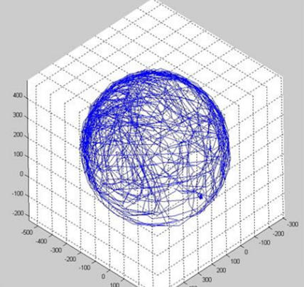
Usually, when a device with sensors rotates in various directions in the air, the spatial geometric structure composed of measured values is actually a sphere, and all sampling points fall on the surface of this sphere, as shown in the following figure.

a) Aerial rotation: Use calibrated equipment to perform an 8-shaped movement in the air, aiming for the normal direction of the equipment to point towards all 8 quadrants of space. By obtaining sufficient sample points, the center O(γx,γy,γz) is determined, which is the size and direction of the fixed magnetic field interference vector.
b) Sample point collection: When rotating the device in various directions in the air, the spatial geometric structure composed of measurement values is actually a sphere, and all sampling points fall on the surface of this sphere. By using these sample points, the center of the circle can be determined to determine the hard magnetic interference value and perform calibration.
Ø Stay away from interference sources: Ensure that there are no large metal objects (such as iron cabinets, vehicles), motors, speakers, or other electromagnetic equipment within 3 meters of the calibration environment.
Ø Horizontal placement: Use a level or built-in sensor to adjust to a horizontal state, ensuring that the measurement is based on the horizontal component of the geomagnetic field.
Ø Fixed method: Avoid wearing metal watches or rings when holding the device; If it is an embedded device (such as a drone), ensure a stable installation.
a) Manual triggering: Refer to the product manual, common methods include:
n Key combination (such as long pressing the power and function keys for 5 seconds).
n Software instructions (select 'Calibrate Compass' through the accompanying app).
b) Auto prompt: Some devices automatically prompt calibration when detecting magnetic field anomalies (such as continuously displaying "low precision").
a) Horizontal rotation (2D calibration):
n Slowly rotate the equipment around the vertical axis (Z-axis) and keep it horizontal.
n Ensure uniform rotation speed (about 10 seconds/turn), complete at least 2 turns to cover all directions.
b) Three-dimensional rotation (3D calibration, suitable for high-precision equipment):
n Rotate around the X (roll), Y (pitch), and Z (yaw) axes in sequence, with each axis rotating at least 360 °.
n Example action: After horizontal rotation, flip the device upright and then tilt it back and forth.
a) Direction comparison method: Point the device towards a known geographic direction (such as using a compass to determine true north) and check if the readings match.
b) Software validation: Use map apps or professional tools (such as magnetic field analysis software) to observe directional stability and accuracy.
c) Repeat calibration: If the deviation exceeds the nominal error of the equipment (such as ±3°), recalibration and environmental interference inspection are required.

Xml Privacy Policy Blog Sitemap
copyright @ Micro-Magic Inc All Rights Reserved.
 Network Supported
