




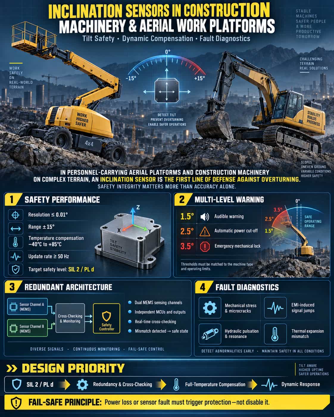
For aerial work platforms carrying personnel and construction machinery operating on complex terrain, inclinometers serve as the first line of defense against overturning accidents. Unlike applications such as solar tracking, the requirements here go beyond mere measurement accuracy; it is equally critical to detect and identify errors should they occur. Safety standards, alarm threshold design, redundant architectures, and failure mode diagnostics collectively form a safety closed-loop for the inclination sensing system. Safety Standards: From Static Coefficients to Sensor Specifications Anti-overturning designs for aerial work platforms are governed by multiple standards. ISO 16368:2020 mandates a static anti-overturning coefficient of ≥1.5 and a dynamic anti-overturning coefficient of ≥2.0 (including a 1.1x dynamic load factor). The standards specify clear requirements for inclinometers: resolution ≤0.01°, a measurement range of ±15°, temperature drift compensation covering -40°C to +85°C, and a data refresh rate of ≥50Hz to prevent missing transient overturning events. Regarding functional safety, EN 280:2013+A1:2015 and ANSI A92.20 require that all self-propelled aerial work platforms cut off drive functions and trigger audible and visual alarms if the chassis tilt exceeds operational limits. Leading safety-grade inclinometers currently achieve SIL 2 (IEC 61508) and PL d (ISO 13849) certification levels. Alarm Thresholds: Multi-level Early Warning and Fail-safe Design Alarm threshold design requires balancing sensitivity against the false alarm rate. A typical multi-level strategy in engineering practice involves: a Level 1 warning (audible alarm) at ≥1.5° tilt, allowing for manual intervention; a Level 2 braking action that automatically cuts off power at ≥2.5°; and an emergency lock that mechanically secures the outrigger cylinders at ≥3.5°. Specific thresholds vary among manufacturers; for instance, some safety-grade sensors trigger a safety contact disconnection at ±8.5° while simultaneously outputting a directional warning signal at ±3° to facilitate platform leveling. Threshold settings must also account for equipment type: diesel-powered equipment typically allows for a tilt angle of 4–5°, whereas most electric-drive platforms allow for 3–4°. A frequently overlooked design principle is "fail-safe" operation: in the event of a power loss or sensor malfunction, the alarm threshold must default to triggering a safe state rather than disabling protection. Redundant Architecture: Dual-Channel and Cross-Checking Single-point failure is unacceptable in man-carrying equipment; redundant design is a prerequisite for safety compliance. The most mature solution in current engineering practice is a fully redundant dual-channel architecture: two independent MEMS accelerometers and microcontrollers form separate tilt-measurement channels, each outputting angle data independently, with real-time fault detection achieved by comparing the difference between the two channels. If the difference exceeds a preset threshold, the system immediately issues an alarm and switches to a safe state. Relevant functional safety standards explicitly state that tilt sensor data may only be treated as safety-critical information when a redundant configuration is used and the control system has been verified via cross-checking functions. For applications requiring higher safety levels, a "two-out-of-three" (2oo3) voting mechanism may be employed to prevent unnecessary downtime caused by false alarms from a single channel. Failure Modes and Fault Diagnosis Typical failure modes for MEMS tilt sensors in construction machinery applications include: micro-cracks in the MEMS chip's cantilever beam caused by mechanical stress—initially manifesting as a deviation of ±0.5°, but leading to total failure as cracks propagate under continuous vibration; signal spikes caused by electromagnetic interference (EMI), such as common-mode noise from IGBT switching in welding stations inducing 300mV interference on RS485 communication lines; and structural resonance resulting from the overlap between hydraulic system pressure pulsations and the sensor's internal low-pass filter cutoff frequency—a phenomenon responsible for a dual-axis sensor failure in a specific tunneling machine. Regarding diagnostics, the industry has developed systematic methods: detecting deviations through dual-channel data comparison, identifying vibration interference via confidence intervals of accelerometer readings, and exposing thermal expansion coefficient mismatches in packaging materials through temperature cycling tests. In summary, when selecting MEMS tilt sensors for construction machinery and aerial work platforms, the primary consideration is not the precision figure, but safety integrity. The priority order should be: SIL 2/PL d functional safety certification → dual-channel redundant architecture with cross-checking capabilities → full-temperature-range compensation specifications → dynamic response bandwidth. For system designers, the critical decisions lie in devising a tiered alarm threshold strategy and implementing fail-safe logic; when the sensor itself becomes the weak link in the safety chain, redundancy and diagnostic capabilities—rather than precision—are the primary determinants of the system's safety boundaries.
Read More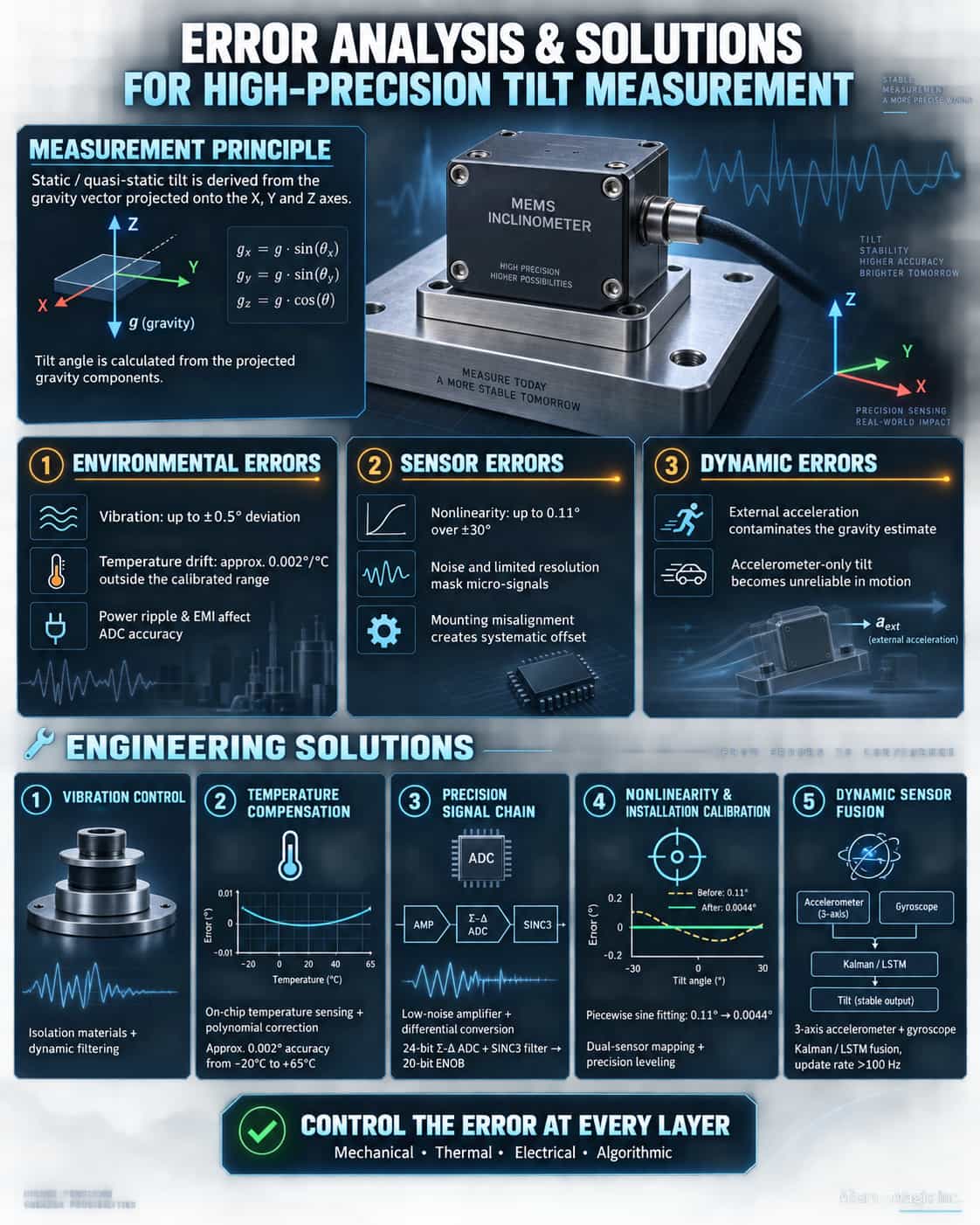
In high-precision inclination measurement, error control directly determines system performance. Errors primarily stem from environmental interference, inherent sensor characteristics, and the effects of dynamic acceleration. To address these errors, a combination of measures can be employed, including vibration-damping design, temperature compensation, power and signal isolation, high-precision signal chain design, nonlinearity correction, installation error correction, and multi-sensor fusion. Suppressing and compensating for these multi-source errors enhances the accuracy, stability, and environmental adaptability of the inclination measurement system, providing a viable technical pathway for engineering design and optimization. 1. Principles of Inclination Measurement Based on MEMS Accelerometers The physical basis for measuring inclination using accelerometers is the vector decomposition of gravitational acceleration. Under static or quasi-static conditions—and in the absence of external acceleration interference—when the device tilts, the components of gravitational acceleration along the accelerometer's three orthogonal axes (X, Y, and Z) change. By measuring the proportional relationships between these components, the device's inclination relative to the direction of gravity can be calculated. 最小化图片 编辑图片 删除图片 2. Analysis of Primary Error Sources 2.1. Environmental Interference Errors Mechanical vibration is a common source of interference. When a sensor is installed on a vehicle platform or industrial equipment subject to vibration, the vibration causes output signal fluctuations, potentially introducing a measurement deviation of approximately ±0.5°. Temperature drift is also significant; temperature fluctuations cause zero-point drift in the sensor. This is particularly pronounced when the operating temperature falls outside the calibrated range (e.g., outside -20°C to 65°C), where temperature drift can reach approximately 0.002°/°C. Furthermore, power supply fluctuations or external electromagnetic fields can interfere with the sensor's signal chain, affecting analog-to-digital conversion accuracy and thereby reducing the reliability of measurement results. 2.2. Inherent Sensor Errors The relationship between the output of a MEMS inclinometer and the actual tilt angle is not perfectly linear. For instance, some T7-A series sensors exhibit non-linearity errors of up to 0.11° within a ±30° range. Noise and resolution limitations also impact accuracy; improper analog signal processing or insufficient ADC bit depth may prevent the effective detection of minute signals (on the order of 0.175 mV), resulting in reduced effective resolution. Additionally, installation errors constitute a form of systematic error. An uneven base, insecure mounting, or a lack of parallelism between the mounting surface and the surface being measured can cause deviations in the sensor's reference plane, thereby affecting measurement results. 2.3. Dynamic Interference Errors When the device is subject to external acceleration—such as vibration or motion—dynamic acceleration components contaminate the accelerometer output, leading to errors in tilt angle calculation. Relying solely on the accelerometer makes it difficult to obtain an accurate tilt angle; therefore, data fusion with a gyroscope or magnetometer—using methods such as Kalman filtering—is required. 3. Error Mitigation Solutions and Key Technologies 3.1. Environmental Interference Suppression Technologies Vibration Damping Design: Vibration isolation materials, such as rubber pads, can be used to isolate vibration sources, or sensors with dynamic filtering capabilities can be selected to minimize the impact of vibration on the output. Temperature Compensation: At the hardware level, MEMS chips with built-in temperature sensors can be selected to correct drift via real-time temperature monitoring. At the software level, a temperature-error curve fitting equation can be established using polynomial compensation algorithms to control temperature-induced drift to approximately 0.002° within the -20°C to 65°C range. Power and Signal Isolation: A high-stability voltage reference (e.g., LM236) is used to power the sensor, and decoupling circuitry is designed to minimize the impact of power supply ripple on the signal chain. 3.2. Sensor Signal Optimization Techniques High-Precision Signal Chain Design: Low-noise operational amplifiers (e.g., ICL7653) and differential conversion circuits (e.g., AD8138AR) are employed to enhance the common-mode rejection ratio (CMRR) and signal-to-noise ratio (SNR). A 24-bit Sigma-Delta ADC (e.g., the integrated ADC in the C8051F350) is used in conjunction with a SINC3 filter to reduce noise, achieving an effective resolution of 20 bits. Non-linearity Correction: By subdividing the measurement range and applying piecewise sinusoidal curve fitting, non-linearity error is reduced from 0.11° to 0.0044°, significantly improving measurement consistency across the full scale. 3.3. Installation Error Correction Dual-Sensor Mapping Method: A primary tilt sensor serves as the calibration reference on the mounting platform, while a second sensor acts as the unit under calibration. Their coordinated operation establishes a linear mapping relationship between the driven angle and the measured angle, thereby correcting mechanical installation deviations. Leveling Calibration: A high-precision level is used to calibrate the mounting surface, ensuring the sensor's reference plane is parallel to the surface being measured; the base is secured using torque screws to minimize installation drift during long-term operation. 3.4. Dynamic Error Compensation Algorithms Multi-Sensor Fusion: By integrating a 3-axis accelerometer and a gyroscope, and employing algorithms such as Kalman filtering or LSTM to predict dynamic tilt angles, the update rate is increased to over 100 Hz, improving dynamic response and measurement stability. Catenary Model Optimization: For specific scenarios such as dynamic conductor deformation, safety thresholds are adjusted in real-time based on the catenary equation and environmental parameters (e.g., wind speed, temperature), reducing the false alarm rate to below 0.3%.
Read More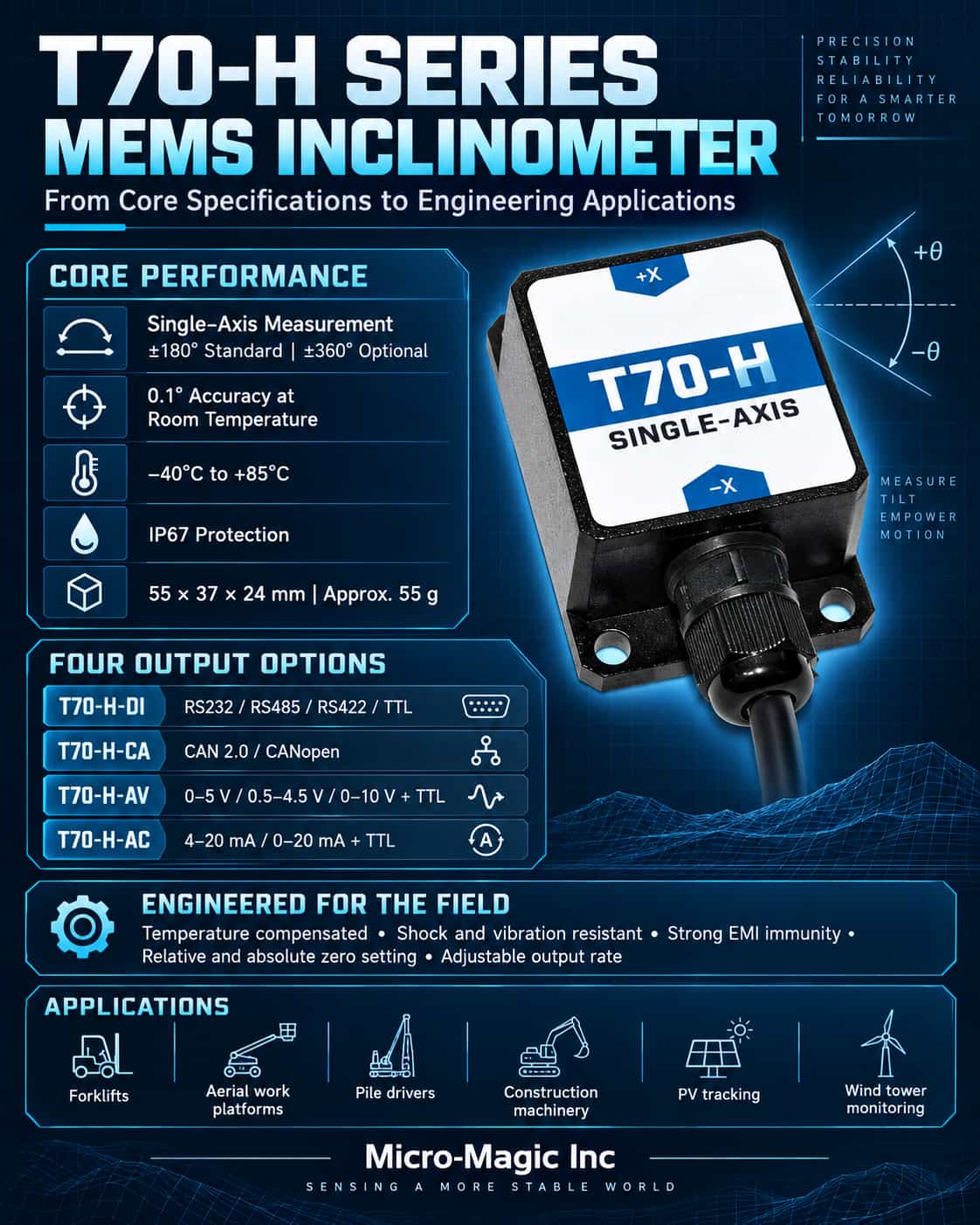
When selecting MEMS inclinometers, datasheets often list over a dozen parameters; however, the factors that truly determine system performance generally boil down to six key specifications: measurement range, accuracy, resolution, zero-bias, temperature drift, and frequency response. Understanding the definitions, testing conditions, and interdependencies of these parameters is far more important than simply comparing numerical values. Measurement Range: Bigger Is Not Always Better The measurement range refers to the span of tilt angles a sensor can measure; common options include ±10°, ±30°, ±60°, and ±90°, with some products supporting single-axis or dual-axis measurement. The primary rule for selecting a range is to cover the maximum actual tilt angle while maintaining a safety margin. However, there is often a trade-off between range and accuracy: within the same product series, a sensor with a ±10° range typically offers superior accuracy across the full temperature range compared to one with a ±90° range. This is because, with wider ranges, it is more difficult to control the nonlinearity of the MEMS sensing structure, packaging stresses, and cross-axis errors. Therefore, if the actual operating conditions require only ±15°, selecting a ±30° range is usually more sensible than choosing a ±90° range. Additionally, while the X and Y axes of a dual-axis sensor may share the same range, the mounting orientation affects the effective measurement axes; thus, one must ensure alignment between the measurement axes and the mechanical axes during selection. Accuracy: A Composite Error Concept Accuracy is frequently misunderstood as merely the "error of a single measurement." In reality, it usually refers to absolute accuracy—a composite result encompassing various error sources such as nonlinearity, repeatability, hysteresis, zero-bias, and cross-axis error. When reviewing datasheets, it is crucial to pay attention to testing conditions, as there is often a significant difference between accuracy at room temperature and accuracy across the full operating temperature range. For instance, an industrial-grade, dual-axis digital inclinometer might specify a full-temperature-range accuracy of 0.01° to 0.05° (across -40°C to +85°C), while its accuracy at room temperature could be even better. Priority should be given to full-temperature-range accuracy during selection, as temperature fluctuations in outdoor or industrial environments can directly amplify errors. If the system only requires monitoring relative angular changes, calibration against a "relative zero point" can eliminate some zero-bias, though it cannot eliminate errors caused by temperature drift or nonlinearity. Resolution: The Ability to Distinguish Does Not Equal Measurement Accuracy Resolution refers to the smallest angular change a sensor can detect and distinguish; typical values range from 0.001° to 0.002°, with high-precision products reaching 0.0005°. While resolution is primarily determined by ADC bit depth, noise levels, and filtering algorithms, it is not synonymous with accuracy. A sensor with a resolution of 0.001° might have an actual accuracy of 0.05°. High resolution is valuable for static leveling and monitoring slow tilts, but in vibrating environments, excessively high resolution can amplify noise. Therefore, resolution should be balanced against noise density, bandwidth, and actual control requirements rather than simply pursuing the lowest numerical value. Bias: The Starting Error in Absolute Angle Measurement Bias is the deviation between the sensor's actual output and the theoretical zero point when positioned at zero inclination. Although bias directly affects absolute angle measurements, it can be corrected through field calibration or by setting a relative zero point. A more challenging issue is bias temperature drift—the shift in the zero point caused by temperature changes—usually measured in °/°C. For instance, a temperature drift of ±0.008°/°C results in a zero-point shift of approximately 0.24° given a 30°C temperature change; this is significant for high-precision tracking or safety-critical control. Long-term bias stability is equally critical, as it determines the magnitude of zero-point drift after a year of operation. When selecting a sensor, focus on "bias temperature drift" and "long-term stability" rather than just the initial bias. Temperature Drift: The Key to Accuracy Across the Full Temperature Range Temperature drift comprises zero-point drift and sensitivity drift. Zero-point drift manifests as an overall shift in angular output with temperature changes, whereas sensitivity drift involves the scaling factor changing with temperature (commonly measured in ppm/°C). Modern industrial-grade MEMS inclinometers typically feature built-in temperature sensors that provide real-time compensation via polynomial fitting or look-up tables, ensuring repeatability in both low- and high-temperature environments. However, the effectiveness of this compensation depends on the quality of factory calibration. When evaluating temperature drift, request accuracy curves covering the full operating range (e.g., -40°C to +85°C) from the manufacturer, rather than relying solely on room-temperature specifications. In applications subject to drastic temperature fluctuations, temperature drift specifications should take precedence over room-temperature resolution. Frequency Response: The Divide Between Static and Dynamic Applications Frequency response determines whether a sensor can keep pace with angular changes. Static tilt measurement requires only DC response and an output rate of 5–15 Hz. In contrast, dynamic measurements—such as platform leveling, vibration monitoring, and wind-induced vibration analysis for tracking mounts—demand higher bandwidths and output rates, typically ranging from 35 Hz to 100 Hz. However, high output rates introduce increased noise and communication overhead; in RS-485 half-duplex mode, continuous high-frequency output can interfere with command reception, making a request-response mode or a higher baud rate advisable. Response time, startup time, and filter cutoff frequency must also be considered: excessive filtering causes lag, while insufficient filtering results in high noise levels. In engineering practice, a moving average or low-pass filter is often applied at the controller level to strike a balance between response speed and noise suppression. Parameter Interdependence and Selection Sequence These six parameters are not independent: measurement range affects accuracy; temperature drift impacts accuracy across the full operating temperature range; resolution is constrained by noise and bandwidth; and zero-bias temperature drift determines long-term stability. A logical selection sequence is as follows: first, determine the measurement range and number of axes; next, define the operating temperature range and accuracy requirements across that range; then, evaluate zero-bias temperature drift and long-term stability; and finally, select the output rate and resolution based on the required control bandwidth. Interface type, ingress protection (IP) rating, and shock/vibration resistance are considered additional requirements at the system integration level. In summary, the key to understanding the core parameters of MEMS tilt sensors lies not in memorizing specific figures, but in grasping the definition, testing conditions, and engineering implications of each parameter. The measurement range must match the actual tilt angle; accuracy must be assessed across the full temperature range; resolution requires a balance with noise and bandwidth; zero-bias and temperature drift determine long-term reliability; and frequency response dictates suitability for dynamic applications. Only by comprehensively evaluating these parameters within the specific application context can one select a tilt sensor that is truly suitable for the system.
Read More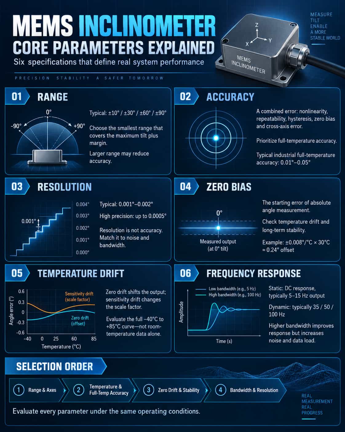
When selecting a MEMS inclination sensor, the data sheet often lists more than a dozen parameters, but the six parameters that really determine the system performance are usually the range, accuracy, resolution, bias, temperature drift and frequency response. Understanding their definitions, test conditions, and coupling relationships between them is more important than simply comparing numbers. Measuring range: bigger is not better The measuring range is the tilt angle range that the sensor can measure. Common options include ±10°, ±30°, ±60°, ±90°, etc. Some products support single-axis or dual-axis measurement. The first principle of range selection is to cover the actual maximum inclination angle and leave a safety margin, but there is usually a trade-off between range and accuracy: in the same series of products, the accuracy of the full temperature range of the ±10° range is often better than the ±90° range. This is because the nonlinearity, packaging stress and cross-axis errors of MEMS sensitive structures at large ranges are more difficult to control. Therefore, if the actual working condition only requires ±15°, it is usually more reasonable to choose the ±30° range than ±90°. In addition, the X- and Y-axis measuring ranges of dual-axis sensors may be the same, but the installation direction will affect the effective measuring axis. When selecting, make sure that the measuring axis is consistent with the mechanical axis. Accuracy: A comprehensive error concept Accuracy is often misunderstood as "error of a single measurement". In fact, it is usually absolute accuracy, including the comprehensive result of multiple errors such as nonlinearity, repeatability, hysteresis, zero deviation, and horizontal axis error. The accuracy in the data sheet must pay attention to the test conditions: there is a big difference between normal temperature accuracy and full temperature range accuracy. For example, the full temperature range accuracy of an industrial-grade digital output dual-axis inclination sensor in the range of -40°C to +85°C is 0.01° to 0.05°, but it may be better at room temperature. When selecting a model, you should give priority to the accuracy in the full temperature range, because temperature changes in outdoor and industrial sites will directly amplify the error. If the system only needs relative angle changes, part of the zero offset can be eliminated through "relative zero point" calibration, but temperature drift and nonlinearity cannot be eliminated. Resolution: being able to distinguish does not mean accurate measurement Resolution is the smallest angular change that the sensor can detect and distinguish. It is commonly 0.001°~0.002°, and high-precision products can reach 0.0005°. The resolution is mainly determined by the number of AD bits, noise level and filtering algorithm, but it is not equal to accuracy. A sensor with a resolution of 0.001° may have an actual accuracy of 0.05°. High resolution is valuable in static leveling and slow tilt monitoring, but in a vibration environment, excessive resolution will amplify noise. Therefore, the resolution should match the noise density, bandwidth and actual control needs, rather than blindly pursuing the minimum value. Zero offset: starting point error of absolute angle Zero bias is the deviation between the actual output of the sensor at the zero inclination position and the theoretical zero point. Zero offset directly affects absolute angle measurement, but can be corrected through on-site calibration or relative zero setting. What's more troublesome is the zero bias temperature drift, which is the drift of the zero point with temperature changes. The unit is usually °/℃. For example, zero temperature drift of ±0.008°/°C will introduce a zero point offset of approximately 0.24° at a temperature difference of 30°C, which cannot be ignored for high-precision tracking or safety control. The long-term stability of the zero bias is also critical, as it determines the zero drift of the sensor after one year of operation. When selecting, you should pay attention to "zero bias temperature drift" and "long-term stability", rather than just looking at the initial zero bias. Temperature drift: the key to accuracy across the entire temperature range Temperature drift is divided into zero point temperature drift and sensitivity temperature drift. The zero-point temperature drift is represented by the overall deviation of the angle output with temperature; the sensitivity temperature drift is represented by the change of the proportional factor with temperature, and the commonly used unit is ppm/℃. Modern industrial-grade MEMS inclination sensors usually have built-in temperature sensors and perform real-time compensation through polynomial fitting or look-up table methods to ensure repeatability in low and high temperature environments. But the compensation effect depends on the factory calibration quality. When evaluating temperature drift, manufacturers should be required to provide a full temperature range accuracy curve of -40°C to +85°C, rather than just looking at normal temperature indicators. If the application environment temperature changes drastically, the temperature drift index should take priority over the normal temperature resolution. Frequency response: the watershed between static and dynamic Frequency response determines whether the sensor can keep up with changes in angle. Static inclination measurement only requires DC response and an output rate of 5Hz~15Hz; dynamic measurements such as platform leveling, vibration monitoring, and tracking bracket anti-wind vibration require higher bandwidth and output rate, commonly 35Hz, 50Hz or even 100Hz. However, high output rates will bring increased noise and communication pressure. High-frequency automatic output in RS485 half-duplex mode may also affect command reception. In this case, it is recommended to use question and answer mode or increase the baud rate. Response time, start-up time and filter cutoff frequency also need to be considered: too much filtering will cause lag, and too light filtering will cause loud noise. In engineering, moving average or low-pass filtering is usually performed on the controller side to strike a balance between response speed and noise suppression. Parameter coupling and selection sequence The six parameters are not independent: the measurement range affects the accuracy, the temperature drift affects the accuracy in the full temperature range, the resolution is restricted by noise and bandwidth, and the zero-bias temperature drift determines long-term stability. A reasonable selection sequence is: first determine the range and number of measurement axes, then clarify the operating temperature range and full temperature zone accuracy requirements, then look at the zero bias temperature drift and long-term stability, and finally select the output rate and resolution based on the control bandwidth. Interfaces, protection levels, and shock and vibration resistance are additional conditions at the system integration level. To sum up, the key to analyzing the core parameters of MEMS inclination sensors is not to remember the numbers, but to understand the definition, test conditions and engineering impact of each parameter. The measuring range must match the actual tilt angle, the accuracy depends on the full temperature range, the resolution must be balanced with noise and bandwidth, the zero bias and temperature drift determine long-term reliability, and the frequency response determines dynamic applicability. Only by comprehensively evaluating these parameters in the same application scenario can the inclination sensor that is truly suitable for the system be selected.
Read More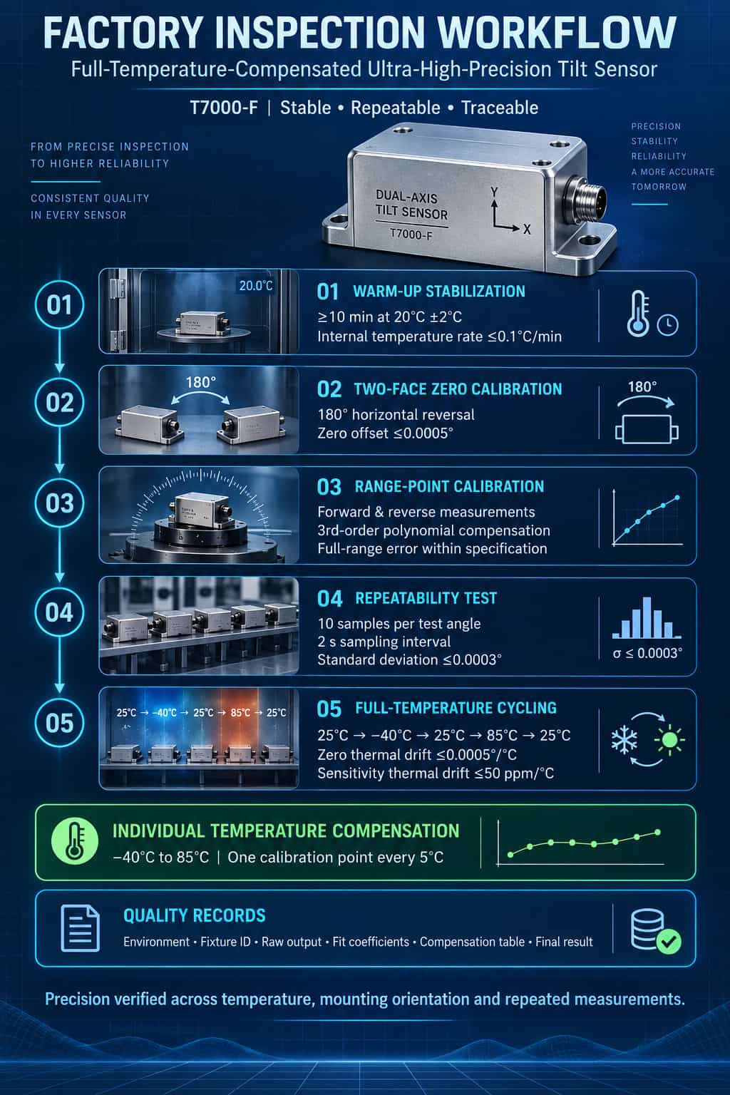
Indicated value error and repeatability are the core performance indicators for ultra-high-precision inclinometers featuring full-temperature compensation: the former reflects the deviation between the reading at a specific angle and the true angle, while the latter reflects the consistency of measurements taken multiple times under identical conditions. Using the T7000-F as an example, this article outlines its factory inspection process—covering warm-up stabilization, zero-point calibration via the dual-side method, full-scale point calibration, repeatability testing, and full-temperature cycling—to ensure stable, repeatable, and traceable output across varying temperatures, mounting surfaces, and measurement conditions. 1. Core Indicators and Inspection Logic The T7000-F utilizes MEMS sensing technology and full-temperature compensation algorithms to achieve an absolute accuracy of 0.001° within a ±5° measurement range. For products of this class, factory inspection must go beyond single-point output checks at room temperature; instead, a comprehensive testing sequence centered on "indicated value error" and "repeatability" is required. The inspection process typically includes static warm-up, zero-point calibration, full-scale point calibration, repeatability verification, and full-temperature cycling. Raw data, environmental conditions, and pass/fail results are recorded at each stage to create traceable quality records. 2. Warm-up Stabilization After power-on, the sensor must remain undisturbed for at least 10 minutes, during which no commands are sent. The ambient temperature is maintained at 20°C ± 2°C. Real-time monitoring of the internal temperature sensor confirms that the rate of temperature change does not exceed 0.1°C/min. Additionally, the difference in zero-point output between the start and end of the warm-up period is recorded as a characteristic parameter of the device's "thermal stabilization time." The purpose of warm-up stabilization is to eliminate the impact of initial thermal transients on the MEMS sensing element and internal circuitry. For ultra-high-precision inclinometers, insufficient warm-up directly introduces zero-point drift, leading to distorted data in subsequent calibration and testing. 3. Zero-Point Calibration via Dual-Side Method The T7000-F is mounted on a Grade 0 surface plate with a flatness tolerance of no more than 0.005 mm. With the sensor facing upward, the X- and Y-axis outputs are recorded; the sensor is then rotated 180° horizontally around its vertical axis, and the X- and Y-axis outputs are recorded again. The zero-point error for each axis is calculated based on these two sets of readings. The acceptance criterion is that the zero-point deviation, calculated using the dual-sided method, must not exceed 0.0005°. If the zero-point deviation exceeds the limit, the sensor structure is typically deemed abnormal—potential causes include misalignment of the internal sensitive axis or abnormal packaging stress—requiring the unit to be returned for re-inspection. The dual-sided method effectively isolates the sensor's intrinsic zero-point error from errors caused by mounting surface tilt or fixture references, making it a critical step in the zero-point calibration of ultra-high-precision inclinometers. 4. Full-Scale Point Calibration Full-scale point calibration is performed using a high-resolution optical indexing head. The T7000-F is rigidly mounted onto the indexing head's platform, ensuring the sensor's sensitive axis is perpendicular to the indexing head's axis of rotation. The indexing head is rotated to target angles in both forward and reverse directions; the T7000-F's output value is recorded after a 5-second stabilization period. Polynomial fitting—typically using a third-order polynomial—is applied to the indicated value errors from both forward and reverse rotations. The resulting fitting coefficients are written to the sensor to implement non-linearity compensation. Ultimately, the indicated value error across the entire measurement range must not exceed the accuracy specification. Measuring in both directions is essential to capture hysteresis error—the difference in output for the same input angle between the forward and reverse strokes. This stage embodies the core logic of the factory inspection for ultra-high-precision inclinometers with full-range temperature compensation: it goes beyond merely verifying compliance to ensure—through fitting and compensation—that each unit achieves its nominal accuracy during actual operation. 5. Repeatability Test The repeatability test verifies the consistency of sensor measurements taken multiple times under identical conditions and angles. The indexing head is set to three typical angles: zero position (0°), mid-range (+15°), and full-scale (+30°). Ten consecutive samples are taken at each angle with a 2-second interval between samples; output values are recorded, and repeatability is calculated based on the root-mean-square error (RMSE). The acceptance criterion is that the standard deviation of repeatability ($s$) must not exceed 0.0003°. If this limit is exceeded, potential causes include loose mechanical connections, excessive power supply noise, or anomalies in the MEMS sensing element. Repeatability testing serves as a crucial basis for evaluating sensor short-term stability and fixture reliability; it is also a key step in factory inspection for distinguishing between "accurate in a single instance" and "consistently reliable" performance. 6. Full-Temperature Cycling Test For MEMS inclinometers, the primary source of error is typically temperature rather than nonlinearity. Consequently, full-temperature cycling tests are conducted to verify the sensor's temperature characteristics. During the test, the T7000-F is fixed at a non-zero angle (e.g., +10°) without altering the mechanical angle throughout the process. Angle outputs are recorded at specific temperature points—25°C, -40°C, 25°C, 85°C, and a return check at 25°C—to calculate zero-point temperature drift and sensitivity temperature drift. Acceptance criteria are set as follows: zero-point temperature drift ≤ 0.0005°/°C; sensitivity temperature drift ≤ 50 ppm/°C. These specifications are not derived from theoretical calculations but are based on actual measurements and compensation data obtained for each individual chip. A temperature compensation table is generated for every sensor, covering the range from -40°C to 85°C with compensation points set every 5°C; real-time interpolation is used for compensation during operation. Full-temperature cycling is a core step in the factory inspection of products featuring full-temperature compensation. Only through actual measurements across the entire temperature range, the creation of individualized compensation tables, and real-time firmware application can the sensor maintain ultra-high precision output across a wide temperature range. 7. Evaluation, Compensation, and Traceability Upon completion of the aforementioned tests, a comprehensive evaluation is performed for each sensor. Inspection records must include the ambient temperature, fixture ID, dividing head reading, raw output, curve-fitting coefficients, the temperature compensation table, and the final pass/fail result. Non-conforming units are categorized by the type of anomaly—such as structural, assembly, electrical noise, or sensing element issues—and subjected to appropriate rework or re-inspection procedures. In summary, the factory inspection process for the T7000-F demonstrates that quality control for ultra-high-precision inclinometers with full-temperature compensation is not merely a test of isolated metrics, but a complete closed-loop process covering thermal stability, zero-point accuracy, measurement range, repeatability, and temperature characteristics. The ultimate objective is to ensure that angle outputs remain stable, repeatable, and traceable across varying temperatures, mounting surfaces, and repeated measurement cycles. This process offers a general reference for similar ultra-high-precision inclinometers featuring full-temperature compensation.
Read More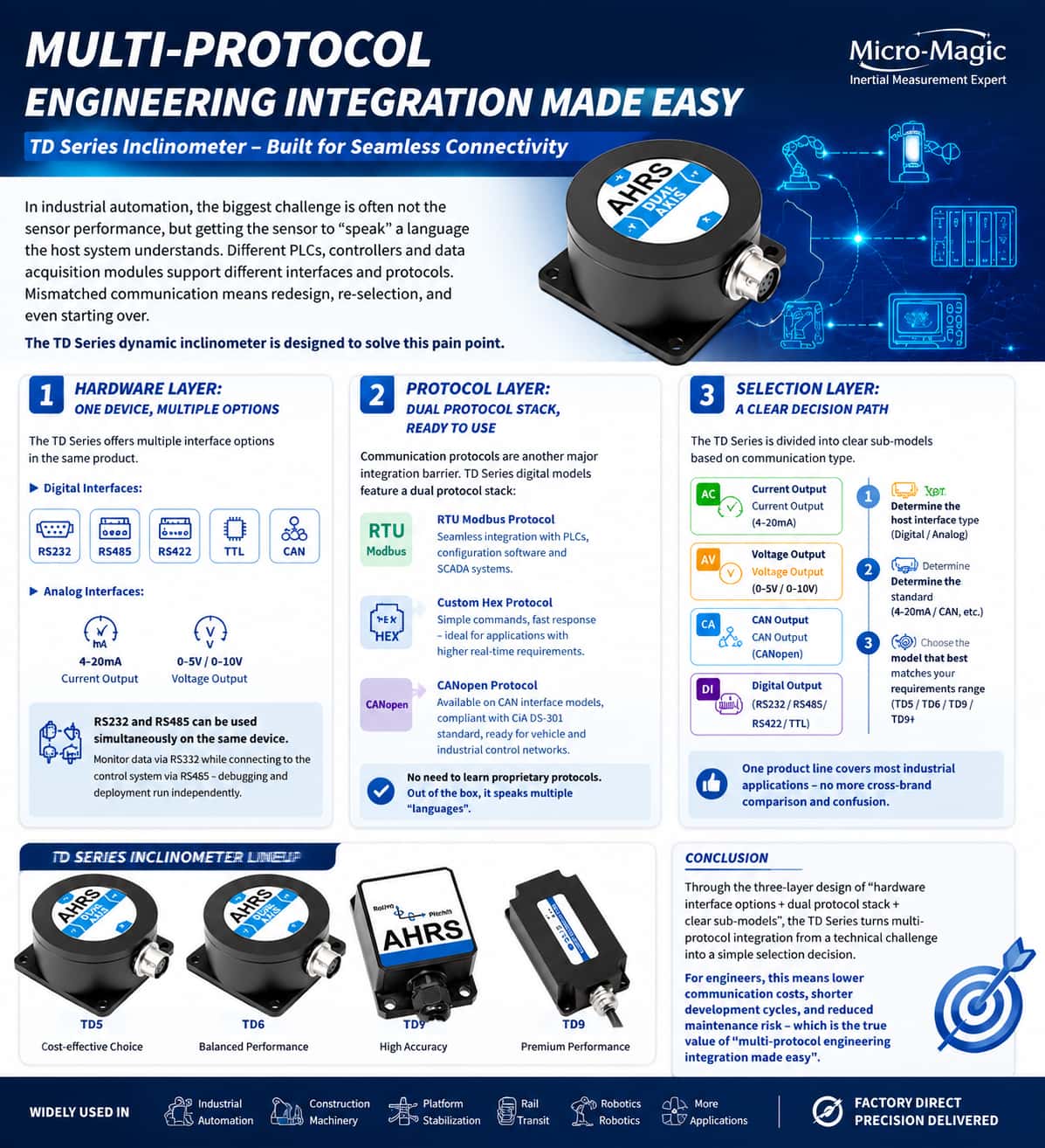
In the era of rapid development in industrial automation and the Internet of Things (IoT), the "communication capability" between sensors and control systems often determines the complexity of project implementation and overall system reliability. With their extensive communication interface configurations, the TD series of dynamic inclinometers offers flexible, comprehensive solutions for attitude measurement needs across diverse scenarios. 1. Overview of Communication Interfaces: Flexible Selection and Adaptation The TD series encompasses a wide range of models covering all mainstream communication methods used in the industrial sector, broadly categorized into digital and analog interfaces. Digital interfaces include RS232, RS485, RS422, TTL, and CAN bus; analog interfaces are available in both current and voltage types, supporting outputs such as 4–20mA and 0–20mA (current) and 0–5V, 0.5–4.5V, and 0–10V (voltage). Regarding communication protocols, the products are compatible with Modbus RTU, the custom 0x68 protocol, and CANopen, truly achieving "multi-purpose functionality and on-demand adaptation." 2. Digital Interfaces: Flexible Data Exchange Channels TD series models with digital interfaces support various output methods, including RS232, RS485, RS422, TTL, and CAN. This "multi-interface" design philosophy allows engineers to select the communication method best suited to their specific requirements: RS232 is ideal for short-range, point-to-point communication, offering ease of debugging and strong compatibility. RS485 supports long-distance transmission of up to 2,000 meters and allows for multiple sensor nodes, making it the preferred choice for industrial fieldbuses. RS422 supports full-duplex communication, making it suitable for scenarios requiring simultaneous data transmission and reception. TTL operates at 3.3V/5V logic levels, facilitating direct integration with embedded systems (such as STM32 and Arduino). CAN bus is designed specifically for automotive and industrial control applications, offering robust interference resistance and high real-time performance. 3. Analog Interfaces: Classic, Reliable Industrial Signals For traditional industrial environments that still rely heavily on PLC analog data acquisition modules, the TD series provides a comprehensive range of analog output solutions. Current-output models support 4–20mA, 0–20mA, and 0–24mA ranges. The 4–20mA range is the most common industrial standard, offering advantages such as strong noise immunity and suitability for long-distance transmission. Zero-point output corresponds to 12mA (for the 4–20mA mode) or 10mA (for the 0–20mA mode), with angle calculation based on a simple, reliable linear proportional relationship. Voltage-output models support three output ranges—0–5V, 0.5–4.5V, and 0–10V—ensuring compatibility with the analog input modules of various PLCs. Zero-point output corresponds to 2.5V (for the 0–5V mode) or 5V (for the 0–10V mode), utilizing a similarly straightforward calculation method. The primary advantage of analog interfaces is their "plug-and-play" capability; there is no need to write complex communication protocols. Angle values can be derived directly by acquiring voltage or current readings via an ADC, significantly lowering the barrier to system integration. 4. Communication Protocols: A Blend of Standardization and Customization At the protocol level, the TD series balances standardization with flexibility. The Modbus RTU protocol, a de facto standard in industrial automation, is widely supported via the RS485 interface. By using standard Modbus function codes (such as 0x03 for data reading), the device can easily interface with various PLCs, HMI/SCADA software, and control systems. The custom protocol is a highly efficient hexadecimal communication protocol used by digital models. Data frames begin with the identifier 0x68 and include fields for data length, address code, command word, data payload, and checksum. This protocol supports a comprehensive range of functions—including reading single-axis or dual-axis angles, setting relative/absolute zero points, adjusting baud rates, toggling between request-response and automatic output modes, and modifying module addresses—all characterized by concise commands and rapid response times. The CANopen protocol is specifically designed for products with CAN interfaces and utilizes the standard CANopen protocol stack. Parameter configuration is handled via SDOs (Service Data Objects), while real-time angle data transmission occurs via PDOs (Process Data Objects). It supports features such as node ID configuration (default 0x05), baud rate settings (configurable from 100kbps to 1Mbps), and multiple data output rates (5Hz to 50Hz), fully meeting the requirements of industrial control and automotive applications. 5. Selection Recommendations When selecting a model for a specific project, consider the following factors: Control System Interface: If the system already utilizes an RS485 bus, prioritize RS485+Modbus; if using PLC analog modules, opt for 4–20 mA current output or 0–10 V voltage output. Transmission Distance: For long distances (>50 meters), RS485 or 4–20 mA current output is recommended; for short distances, RS232, TTL, or voltage output are suitable options. Real-time Requirements: For high-real-time applications (such as robotics or vehicle control), a CAN interface is recommended; for general industrial monitoring, either digital or analog interfaces will suffice. Multi-node Networking: When multiple sensors need to be connected in parallel, RS485+Modbus or CAN bus is the optimal choice. Conclusion By featuring a dual-interface design (supporting both digital and analog outputs) and compatibility with multiple protocols—including Modbus, custom protocols, and CANopen—the TD series dynamic inclinometers truly embody the design philosophy of "one platform, multiple interfaces, and on-demand adaptation." Whether you are building a new Industrial IoT system or upgrading a traditional PLC control cabinet, the TD series offers the ideal communication solution, making inclinometer data acquisition simpler than ever.
Read More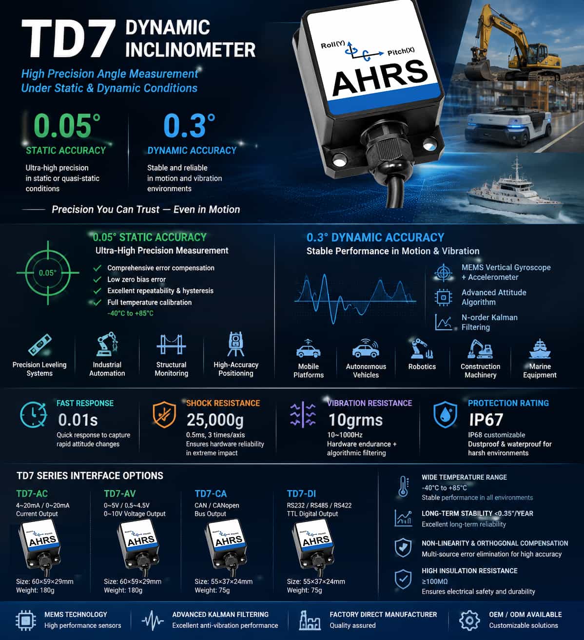
The TD7 series represents a new generation of high-performance dynamic inclinometers, available in four interface configurations: current output (TD7-AC), voltage output (TD7-AV), CAN output (TD7-CA), and digital output (TD7-DI). This series achieves high levels of accuracy in both dynamic and static measurement modes; the key accuracy parameters are detailed below. 1. Dynamic Accuracy vs. Static Accuracy The core accuracy specifications for the TD7 series are a dynamic measurement accuracy of 0.3° and a static accuracy of 0.05°. These figures reflect the sensor's performance under two distinct operating conditions. The dynamic accuracy of 0.3° represents the maximum error when measuring inclination in environments characterized by motion or vibration. The TD7 incorporates an internal vertical gyroscope and accelerometer, an integrated attitude solver, and optimal digital filtering for noise reduction. Combined with an N-order Kalman filter algorithm, it accurately outputs the object's attitude angles even amidst strong vibration and movement. This specification is critical for evaluating the sensor's suitability for applications involving mobile platforms, vehicles, robots, or vibrating machinery. The static accuracy of 0.05° represents the combined error under stationary or quasi-static conditions across the full operating temperature range of -40°C to +85°C. This figure encompasses errors arising from absolute linearity, repeatability, hysteresis, zero-point offset, and horizontal axis misalignment. A static accuracy of 0.05° is considered high-performance in the field of industrial inclination measurement. The nearly six-fold difference between these two values serves as a reminder that accuracy decreases during dynamic operation—an inherent characteristic of dynamic measurement systems. 2. Temperature Drift and Zero-Point Stability The zero-point temperature drift is ±0.01°/°C (for TD7-AC/AV models) or ±0.05°/°C (for TD7-CA/DI models). Taking the TD7-AC as an example, the zero-point may drift by approximately 0.6° when the ambient temperature shifts from 25°C to 85°C. For equipment operating outdoors or across wide temperature ranges, this parameter directly impacts long-term measurement reliability. The sensitivity temperature coefficient is ≤200 ppm/°C (TD7-AC/AV) or ≤150 ppm/°C (TD7-CA/DI). This parameter indicates the extent to which temperature fluctuations affect the sensor's "ratio of output change to angular change." A value of 200 ppm/°C means that for every 1°C change in temperature, the sensitivity undergoes a relative change of approximately 0.02% (two parts in ten thousand). The TD7 series employs various techniques—such as non-linearity compensation, orthogonality compensation, and temperature drift compensation—to eliminate sources of error, ensuring stable measurement performance across a wide temperature range of -40°C to +85°C. 3. Long-term Stability The long-term stability specification is <0.35°. This figure represents the maximum deviation between the sensor's output and its initial value after one year of continuous operation at room temperature. It implies that over the sensor's average service life of 55,000 hours (approximately 6.3 years), accuracy will drift slowly over time, with the maximum deviation remaining within 0.35°. 4. Interpretation of Key Response Time and Environmental Reliability Parameters Response Time (0.01s) This refers to the time required for the output to reach a stable, standard value following a step change in angle. A response speed of 0.01 seconds (10 ms) enables the sensor to track rapid changes in attitude in real-time. This makes it suitable for time-critical applications such as robotic motion control and dynamic marine navigation, serving as the temporal guarantee for achieving 0.3° dynamic accuracy. Shock Resistance (25,000g, 0.5ms, 3 shocks per axis) The sensor's internal MEMS structure sustains no permanent damage or zero-point offset after enduring an instantaneous shock of 25,000 times the acceleration due to gravity. This specification ensures that the device's long-term stability (<0.35°/year) remains unimpaired by accidental events like drops or collisions, acting as the first line of defense for hardware reliability. Vibration Resistance (10grms, 10–1000Hz) In environments subject to broadband random vibration (10–1000 Hz), the sensor not only withstands continuous stress at the hardware level but also effectively filters out vibration as noise using an N-order Kalman filtering algorithm. The synergy between hardware resilience and algorithmic filtering ensures the realization of 0.3° dynamic accuracy during motion. Ingress Protection Rating (IP67; IP68 customizable) IP67 indicates complete protection against dust and the ability to withstand short-term immersion (1 meter depth for 30 minutes), while IP68 meets requirements for long-term, continuous immersion. Featuring a matte-anodized aluminum alloy housing and sealed cabling, the unit effectively prevents moisture and dust ingress—which could otherwise cause circuit corrosion or degrade insulation performance (≥100 MΩ)—ensuring stable, long-term operation in harsh environments such as outdoor, bridge, and marine applications. 5. Model Differences All four models share essentially identical core accuracy specifications (dynamic: 0.3°; static: 0.05°), with the primary differences lying in their output interfaces: TD7-AC: 4–20 mA / 0–20 mA current output; TD7-AV: 0–5 V / 0.5–4.5 V / 0–10 V voltage output; TD7-CA: CAN/CANopen bus output; TD7-DI: Supports multiple digital interfaces, including RS232, RS485, RS422, and TTL. Additionally, the TD7-CA and TD7-DI models are more compact (55 × 37 × 24 mm) and lighter (75 g), whereas the TD7-AC and TD7-AV models measure 60 × 59 × 29 mm and weigh 180 g.
Read More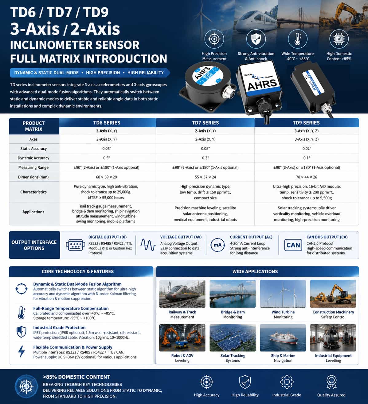
Technical Background: Transitioning from Static Measurement to Dual Static-Dynamic Modes Traditional inclinometers rely on MEMS accelerometers to measure the component of gravitational acceleration along a sensitive axis to calculate the angle, achieving high precision in static or quasi-static environments. However, when the host platform is subject to motion, vibration, or shock, external accelerations superimpose onto the gravitational acceleration, causing significant measurement distortion. This inherent limitation restricts the use of traditional inclinometers in dynamic scenarios such as mobile platforms, construction machinery, and robotics. The TD series of dynamic inclinometers fundamentally resolves this challenge through a fusion architecture combining a 3-axis MEMS accelerometer and a 3-axis gyroscope, alongside a dual-mode fusion algorithm that integrates static and dynamic capabilities. The core technology lies in the system's ability to assess the operating environment in real-time: in static mode, it employs a static algorithm to ensure ultimate precision; in dynamic mode, it automatically switches to a dynamic algorithm based on an N-order Kalman filter. By fusing the low-frequency stability of the accelerometer with the high-frequency response of the gyroscope, the system effectively suppresses measurement errors caused by vibration and shock. This technical approach enables the TD series to consistently output stable and reliable inclination data in complex dynamic environments. Product Matrix: Four Series with Differentiated Positioning The TD series addresses a wide range of needs, spanning from standard industrial-grade requirements to high-precision applications; the products are categorized into four tiers based on precision levels and application scenarios: Product Model Number of axes Static accuracy Dynamic accuracy Dimensions (mm) Positioning TD5 Three-axis 0.1° 0.5° 66×56×29 Standard industrial grade, dual dynamic/static modes TD6 Dual-axis 0.06° 0.5° 60×59×29 Dynamic type, high vibration resistance TD7 Dual-axis 0.05° 0.3° 55×37×24 High-precision dynamic, compact design TD9 Three-axis 0.02° 0.1° 78×44×26 Ultra-high precision, dual dynamic/static modes The TD5 series serves as a standard industrial-grade tri-axial inclinometer, offering a static accuracy of 0.1° and a dynamic accuracy of 0.5°. Featuring an integrated tri-axial accelerometer and gyroscope, it supports tilt monitoring across X, Y, and Z axes, with a measurement range of ±90° (tri-axial) or ±180° (optional single-axis). With a domestic content rate exceeding 85%, it is suitable for industrial applications such as forklift balance control, aerial work platforms, unloading machinery, and anti-tip protection for charging piles. The TD6 series is positioned as a purely dynamic dual-axis inclinometer, specifically designed for mobile platforms and high-vibration environments. It delivers a static accuracy of 0.06° and a dynamic accuracy of 0.5°, utilizing an integrated vertical gyroscope and an N-order Kalman filter algorithm. Error sources are eliminated through multiple techniques, including non-linear compensation, orthogonality compensation, and temperature drift compensation. With a Mean Time Between Failures (MTBF) of ≥55,000 hours and a shock tolerance of 25,000g, it excels in high-dynamic scenarios such as railway gauge measurement, bridge and dam monitoring, marine navigation attitude measurement, and wind turbine oscillation monitoring. The TD7 series represents high-precision dynamic inclinometers, boasting an improved static accuracy of 0.05° and a dynamic accuracy of 0.3°. Building upon the TD6, it features further optimized temperature drift control (≤150 ppm/℃) and a compact size of 55×37×24mm. It is ideal for applications demanding superior precision and compact dimensions, such as leveling control for precision machine tools, positioning for satellite solar arrays, and medical equipment. The TD9 series is the flagship of the TD lineup, offering exceptional static accuracy of 0.02° and dynamic accuracy of 0.1°. It incorporates a high-precision 16-bit A/D module and a temperature sensor, featuring a sensitivity temperature coefficient of ≤200 ppm/℃ and a shock tolerance of 5,500g. It supports tri-axial (X, Y, Z) tilt monitoring and is widely used in applications requiring extreme measurement precision, such as photovoltaic tracking systems, verticality monitoring for piling rigs, and vehicle overload monitoring. Output Interface Matrix: Comprehensive Coverage of Digital, Analog, and Bus Interfaces Another core advantage of the TD series is its comprehensive range of output interfaces. Each precision series offers three output types—digital, analog, and bus—allowing users to make flexible selections based on the requirements of their backend control systems: Digital Output (DI): Utilizes RS232, RS485, RS422, or TTL signal levels and supports standard Modbus RTU or custom hexadecimal protocols. Data is transmitted directly in digital format with high interference immunity, making it suitable for direct integration with digital systems such as PLCs and industrial PCs. Voltage Output (AV): Outputs an analog voltage signal, facilitating easy connection to traditional voltage-based data acquisition cards or instruments for direct signal reading and processing. Current Output (AC): Uses the industrial standard 4–20 mA current loop output. It offers strong interference immunity, making it particularly well-suited for long-distance transmission and harsh industrial environments. CAN Bus Output (CA): Supports the CAN 2.0 protocol, making it ideal for distributed control systems—such as those in automotive and robotics applications—that require high-speed bus communication. Core Technical Features The entire TD series shares the following core technology platforms: Dynamic-Static Dual-Mode Fusion Algorithm: The system automatically identifies its current operating state by analyzing acceleration and angular velocity data in real time. It employs a static algorithm during stationary periods to ensure maximum precision, and switches to a dynamic algorithm during movement, fusing gyroscope data to compensate for acceleration-induced interference. This mechanism enables a single sensor to handle two vastly different operating conditions: static installation and dynamic carrier applications. Comprehensive Temperature Compensation and Aging: Before leaving the factory, all products undergo rigorous calibration, temperature compensation, and long-term stability (aging) testing. The operating temperature range spans -40°C to +85°C, with a storage temperature range of -55°C to +100°C. Industrial-Grade Protection and Reliability: The entire series features an IP67 protection rating (IP68 available upon request) and comes standard with a 1.5-meter shielded cable that is wear-resistant, oil-resistant, and rated for a wide temperature range. Insulation resistance is ≥100 MΩ, and vibration resistance meets 10 grms (10–1000 Hz) standards. Flexible Communication and Power Supply: Output interfaces include options for RS232, RS485, RS422, TTL, and CAN bus, supporting both Modbus RTU and custom hexadecimal protocols. The wide input voltage range (DC 9–36 V, with 5 V optional) accommodates various power supply conditions found in industrial environments. Selection Recommendations The four products in the TD series form a comprehensive lineup covering a wide spectrum of specifications—ranging from standard industrial grade to ultra-high precision, 3-axis to 2-axis configurations, and general-purpose to compact designs. The TD5 serves as a cost-effective choice for standard industrial applications requiring 3-axis monitoring, while the TD6—with its optimization specifically for dynamic performance—is better suited for mobile platforms and high-vibration environments. The TD7 offers an optimal solution when both high precision and a compact footprint are required. Finally, for applications demanding the utmost precision—such as solar tracking and high-accuracy monitoring—the TD9 represents the pinnacle of domestic MEMS inclinometer technology, delivering a static accuracy of 0.02° and a dynamic accuracy of 0.1°. With a domestic content rate exceeding 85%, the series not only overcomes key technological barriers but also provides industries with complete tilt measurement solutions that span the full range from static to dynamic monitoring and from standard to high-precision performance.
Read More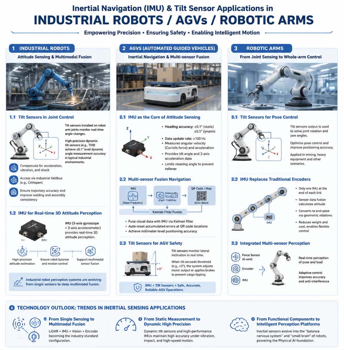
1. Introduction Driven by the wave of intelligent manufacturing and automation, industrial robots, Automated Guided Vehicles (AGVs), and robotic arms are becoming core execution units in modern industrial production systems. However, whether it involves high-speed AGVs navigating complex factory floors or multi-axis robotic arms performing micron-level operations during precision assembly, accurate attitude sensing and motion control are indispensable capabilities. Inertial Measurement Units (IMUs) and inclinometers serve as the core components that provide these devices with functions akin to a "sense of balance" and a "cerebellum." 2. Industrial Robots: Attitude Sensing and Multimodal Fusion Industrial robots operating in scenarios such as welding, assembly, and material handling demand extremely high precision and repeatability regarding motion trajectories. While traditional encoders provide joint angle information, relying solely on them often fails to meet high-precision control requirements—especially under conditions of high-speed movement, vibration, shock, or long-term operation. The introduction of inertial navigation sensors and inclinometers provides a new dimension of attitude sensing for industrial robots. 2.1. Application of Inclinometers in Joint Control In industrial robots, dynamic inclinometers installed at robotic arm joints monitor angular changes across various axes in real time. High-precision dynamic inclinometers—based on 3D MEMS accelerometers and gyroscopes—utilize intelligent algorithms to fuse signals from both sensors. This effectively compensates for the impact of acceleration, vibration, and shock on angular output. For instance, the TD9 model from Maixinminwei achieves dynamic angle measurement accuracy better than ±0.1° in typical industrial environments. Integrating such sensors into control systems via industrial fieldbuses (such as CANopen) enables real-time trajectory calibration, ensuring consistency in tasks like welding and assembly; in automotive manufacturing, this significantly improves the positional accuracy of vehicle body weld points. From a technical perspective, to address issues such as low measurement accuracy and complex control algorithms associated with industrial robot angle sensors, researchers have designed an accuracy analysis method based on smoothing filters. By applying a Savitzky-Golay filter to the raw data acquired by the sensors, output errors are effectively reduced. 2.2. IMU Provides Real-Time 3D Spatial Attitude Sensing The role of Inertial Measurement Units (IMUs) in industrial robots is becoming increasingly critical. An IMU typically comprises a three-axis gyroscope and a three-axis accelerometer; integrating gyroscope data yields changes in attitude, while combining this with accelerometer data allows for the calculation of accurate pitch and roll angles. High-performance MEMS IMUs provide robots with real-time 3D spatial attitude sensing, ensuring stability control and effective mobility. Precision inertial navigation technology is currently making rapid inroads into the industrial robotics sector. Automotive-grade IMU chips, utilizing advanced MEMS designs and ceramic hermetic packaging, offer high precision, high reliability, and stability across a wide temperature range. A trend toward the deep integration of LiDAR sensing and precision inertial navigation has emerged, with the two technologies being combined to develop multi-modal sensor fusion solutions for fields such as embodied AI and industrial robotics. This trend signifies a shift in industrial robot perception systems from single-sensor setups to deep multi-modal fusion. 3. AGV: Inertial Navigation and Multi-Source Fusion Positioning Automated Guided Vehicles (AGVs) are key components of logistics systems in smart factories; their navigation accuracy directly impacts material handling efficiency and production safety. Traditional navigation methods—such as magnetic strip guidance and QR code positioning—suffer from limitations like fixed paths, high deployment costs, and susceptibility to environmental interference. In contrast, the application of inertial navigation and tilt sensors has revolutionized AGV navigation. 3.1. The IMU as the Core of AGV Attitude Sensing The IMU is the core component enabling attitude and motion sensing in AGVs; without it, the vehicle would lose its ability to sense attitude, leading to motion control failure and a significant drop in operational precision. AGV-based IMU modules utilize three-axis MEMS sensors, achieving heading angle accuracy of ±0.1° in static conditions and ±0.5° in dynamic conditions, with data refresh rates typically exceeding 100 Hz. High-precision IMUs measure the Coriolis force via MEMS gyroscopes to accurately detect any angular velocity deviations from linear motion; simultaneously, their accelerometers provide data on the vehicle's tilt (inclination) relative to the horizontal plane and three-axis acceleration. Building on this, the system sets a maximum steering angle threshold to actively limit the steering range during turns, thereby effectively preventing rollovers. 3.2. Multi-sensor Fusion Navigation Single sensors have inherent limitations in complex environments: visual SLAM systems suffer from reduced localization accuracy due to dynamic environmental factors, while inertial navigation systems (INS) are prone to drift errors that accumulate over time. Consequently, multi-sensor fusion has become the mainstream solution for AGV navigation. In practical applications, INS signals are used for AGV state prediction, while path-tracking navigation and RGB-D visual navigation combine to form a multi-camera vision system that corrects accumulated INS errors through system observation. A Kalman filter algorithm fuses visual and inertial data, allowing accumulated errors to be automatically reset at QR code locations. An AGV navigation algorithm combining dual-PID control with inertial navigation technology achieves millimeter-level positioning accuracy via a dual-closed-loop control architecture, while simultaneously reducing the required density of QR code placement. In space-constrained environments with poor satellite signals—such as edible fungus factories—researchers have utilized Error-State Kalman Filters to fuse encoder and IMU data, achieving reliable navigation in narrow aisles and feature-sparse environments. In degraded environments like cable tunnels, visual-inertial SLAM algorithms based on point-line feature fusion effectively resolve localization challenges in settings with repetitive textures. 3.3. Inclinometers Ensuring AGV Operational Safety Inclinometers play a pivotal role in AGV anti-rollover systems. An inclinometer integrated into the AGV chassis dynamically monitors the vehicle's tilt angle during turns or load fluctuations; if the tilt exceeds a preset threshold (e.g., ±5°), the system immediately adjusts motor output power or applies the brakes to prevent cargo from tipping over. Inclinometers with high protection ratings (such as IP69K) are capable of withstanding harsh warehouse conditions, including wet floors and dust. 4. Robotic Arms: From Joint Sensing to Whole-Arm Control Robotic arms are core actuators in industrial automation, and their motion accuracy and flexibility directly determine production quality and efficiency. The application of inertial sensors and inclinometers in robotic arms is evolving from simple angle measurement toward full-state perception and intelligent control. 4.1. Precise Control of Robotic Arm Pose Using Tilt Sensors Tilt sensors play a crucial role in controlling the pose of robotic arms. An existing patented invention discloses a pose control method based on tilt sensors; by constructing a mathematical model and calculating the robotic arm's rotation and yaw angles from the sensor outputs, the method optimizes pose control and enhances positioning accuracy. This technology has already been applied in demonstration projects for intelligent coal mining operations. In heavy equipment such as coal mining roadheaders, mounting explosion-proof dynamic tilt sensors on the cutting boom allows for the measurement of the cutting head's pitch angle. When combined with angle sensors to measure the yaw angle, the system can obtain precise real-time data on the cutting head's orientation relative to the machine body. This system features a simple structure, ease of installation, and strong environmental adaptability. 4.2. IMUs Replacing Traditional Encoders Cable-driven linkage robotic arms feature slender bodies and flexible movement, enabling them to perform tasks such as inspection and maintenance in confined spaces and complex, unstructured environments. However, the large number of kinematic joints makes installing encoders at every joint costly; furthermore, if the robotic arm's outer diameter is too small, suitable encoders may not even be available. To address this challenge, a state-sensing and control method based on external IMUs was developed for cable-driven linkage robotic arms. An IMU is placed at the end of each linkage segment; sensor data fusion is used to calculate the IMU's orientation in real-time, which is then converted into the orientation of the segment's end based on geometric relationships. This approach effectively reduces the robotic arm's weight and enhances control flexibility. In the field of flexible robotic arms, multi-IMU sensor fusion frameworks are employed to estimate position and orientation. Flexible links are modeled as a series of rigid segments, with joint angles estimated using accelerometer and gyroscope data. Implementing closed-loop control via real-time IMU orientation feedback significantly improves the operational robustness and flexibility of the robotic arm. 4.3. Comprehensive Sensing via Multi-Sensor Integration Modern high-precision robotic arm motion control systems are evolving toward multi-sensor integration. By integrating six-axis force sensors, encoders, and IMUs, the system can sense the robotic arm's pose and load in real-time; when combined with adaptive sliding mode control algorithms, this integration significantly enhances motion accuracy and disturbance rejection capabilities. At the end-effector level, methods utilizing IMUs to acquire pose data in real-time can effectively compensate for pose deviations caused by joint torsion and connection errors. 5. Technological Outlook: Deep Multi-Sensor Fusion The application of inertial navigation and inclinometer sensors in industrial robots, AGVs, and robotic arms is characterized by three major trends: First, the evolution from single-mode sensing to multi-modal fusion. Since a single sensor cannot address all the challenges of complex industrial environments, multi-sensor fusion—combining LiDAR, IMUs, vision systems, and encoders—is becoming the industry standard. Second, the shift from static measurement to high-precision dynamic sensing. Traditional static inclinometers can no longer meet the demands of high-speed motion scenarios; conversely, dynamic inclinometers and high-performance IMUs fuse accelerometer and gyroscope data to maintain high-precision output even under conditions of vibration, shock, and rapid movement. Third, the upgrade from functional components to intelligent sensing platforms. Driven by the development of embodied AI and humanoid robots, inertial pose sensors are evolving from simple measurement elements into the "balance nerves" and "cerebellum" of robots. Relevant enterprises have established comprehensive technology and product ecosystems—spanning sensor chips, modules, and system assemblies—that serve as the "physical AI foundation" for robots and intelligent devices.
Read More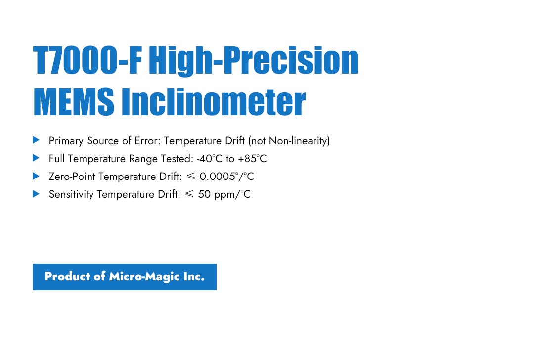
MEMS inclinometers must undergo full-temperature testing, as temperature variation—not nonlinearity—constitutes their largest error source. The elastic modulus of sensitive materials, reference voltage, and amplifier gain all drift with temperature. Full-temperature testing allows these effects to be assessed and compensated, guaranteeing measurement accuracy over the full operating temperature range. Taking the high-precision inclinometer T7000-F manufactured by Micro-Magic Inc as an example, during the full-temperature cycling test, the T7000-F is fixed at a non-zero angle (e.g., +10°) with its mechanical angle kept unchanged throughout the entire process. Starting from room temperature (25°C, ambient temperature), the temperature is decreased to -40°C and held for a sufficient duration. Then, at a set temperature change rate, the temperature is increased to +85°C and held again. Finally, optionally, the temperature may be returned to room temperature. Throughout the entire cycling process, the angular output θ(T) is continuously monitored and recorded at several temperature points: 25°C (ambient temperature), -40°C, 25°C, 85°C, and 25°C (return check). Based on these measurements, the zero temperature drift and sensitivity temperature drift are calculated. Zero temperature drift: ( Take the maximum value as the specification value)。 Sensitivity temperature drift: The acceptance criteria for T7000-F are: zero temperature drift ≤ 0.0005°/℃, and sensitivity temperature drift ≤ 50 ppm/℃. These specifications are derived from actual testing of each product, rather than theoretical calculations. Each sensor is equipped with a temperature compensation table ranging from -40℃ to 85℃ (at 5℃ intervals), which enables precise compensation through real-time interpolation during operation, ensuring measurement accuracy across the full temperature range.
Read More
In today's era where autonomous systems' collaborative operations are becoming increasingly prevalent, providing stable and unified global navigation reference for distributed robotic clusters has always been a key technical challenge. Recently, the C9000 series high-precision six-axis full-attitude electronic compass developed by Micro-Magic Inc was successfully integrated into the next-generation cluster control system of a leading high-end drone system integrator. This integration offers a highly reliable directional benchmark for multi-vehicle cooperative navigation, significantly enhancing the system's overall navigation accuracy and coordination capabilities in complex environments. In the "Intelligent Inspection Drone Group" project, multiple drones are required to conduct collaborative inspections at the wind power plant. The task requires each drone to maintain a consistent heading coordinate system and accurately synchronize and position complex structures such as wind turbine blades and towers. Traditional single point magnetic compasses are susceptible to electromagnetic interference from wind turbine steel structures, leading to heading deviation and subsequently affecting cluster path planning and data fusion. By carrying the C9000 series full attitude electronic compass, each drone can output high-precision three-axis attitude data of heading, pitch, and roll in real time, and effectively suppress interference from strong magnetic environments on site through built-in hard magnetic, soft magnetic, and tilt compensation algorithms. The C9000, with its 0.2 ° heading accuracy and 0.02 ° tilt accuracy, can provide stable attitude output even during large maneuvers of the drone. Its patented full attitude fusion algorithm and extended Kalman filtering technology ensure high data refresh rate and real-time performance during dynamic flight. In addition, the product supports IP67 protection level, with a working temperature range of -40 ℃ to+85 ℃, suitable for harsh outdoor and high-altitude environments, ensuring reliable operation of the system under various weather conditions. The technical leader of the project stated, "The C9000 series not only provides us with precise heading benchmarks, but its multi interface support and flexible calibration modes also greatly simplify the system integration and on-site debugging process. We have significantly improved the environmental adaptability of the cluster system in different wind farms by using its automatic omnidirectional calibration function to quickly calibrate each drone on site before deployment". With the continuous expansion of applications such as autonomous driving, drone formation, and robot collaborative operations, high-precision and strong anti-interference full attitude heading sensors are becoming one of the core components for achieving true "cluster intelligence". The C9000 electronic compass provides a unified, stable, and reliable global heading reference, laying the technical foundation for coordinated operations of multi-agent systems in complex real-world scenarios. It is expected to play a more critical role in unmanned systems, industrial inspection, terrain mapping, and even emergency rescue. C9000-A C9000-B C9000-C
Read More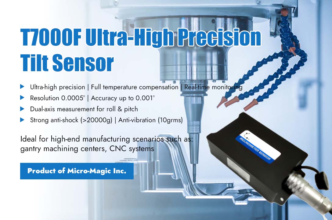
Precision machine tools are the "industrial mother machines" of modern manufacturing, with their machining accuracy directly determining the quality and performance of components. The leveling status of the machine tool serves as the fundamental prerequisite for ensuring this accuracy. Whether in large gantry milling machines, five-axis machining centers, or high-precision grinders, minor foundation settlement, thermal deformation from ambient temperature changes, and the cumulative effects of operational vibrations can all cause the machine table to deviate from its ideal level state. The T7000F series full temperature compensation ultra-high precision dual-axis tilt sensor developed by Micro-Magic Inc has demonstrated excellent application value in the field of precision machine tool horizontal control with its resolution of 0.0005 ° and maximum full temperature range accuracy of 0.001 °. In the industrial application of precision machine tool horizontal control, the value of T7000F is reflected in two key links: equipment installation and commissioning, and operation status monitoring. During the installation phase of the machine tool, T7000F is installed on the key measuring points of the machine tool bed. Multiple sensors are networked through RS485 or CAN bus to obtain real-time absolute tilt values of each measuring point, greatly improving installation and debugging efficiency and accuracy. For large gantry machine tools, the dual axis simultaneous measurement feature can simultaneously monitor the angle changes in both roll and pitch directions, ensuring that the guide rail maintains horizontal consistency throughout the entire length range. During the operation phase of the equipment, sensors are integrated into the machine tool control system for a long time, which can monitor changes in the horizontal state in real time. When the tilt value exceeds the set threshold, it will automatically alarm or cooperate with the automatic leveling device to achieve closed-loop control, effectively preventing batch processing quality accidents caused by changes in machine tool posture. The excellent anti-vibration and anti-shock performance of T7000F sensor is crucial in machine tool applications. Machine tools will generate continuous vibration during high-speed cutting, especially in intermittent cutting processes such as milling and grinding, with complex vibration spectra and high acceleration peaks. T7000F has an shock resistance of over 20000g and a vibration resistance of 10grms, and can be stably installed on the machine bed or worktable for long-term reliable operation. Its IP67 protection level, combined with an aluminum alloy oxidation shell, is sufficient to resist the erosion of cutting fluid, oil mist, and metal dust. In terms of communication interface, the sensor supports multiple bus options such as RS232, RS485, CAN, etc., making it easy to integrate with various CNC systems or PLCs and connect to industrial fieldbus networks without additional protocol conversion. As the manufacturing industry accelerates its evolution toward high-end applications, the demands on foundation accuracy for precision machine tools continue to rise. With its full-temperature-range high precision, strong anti-interference capability, and flexible integration options, the T7000F provides a professional and reliable technical solution for level control in precision machine tools.
Read Moreleave a message
Scan to Wechat :
