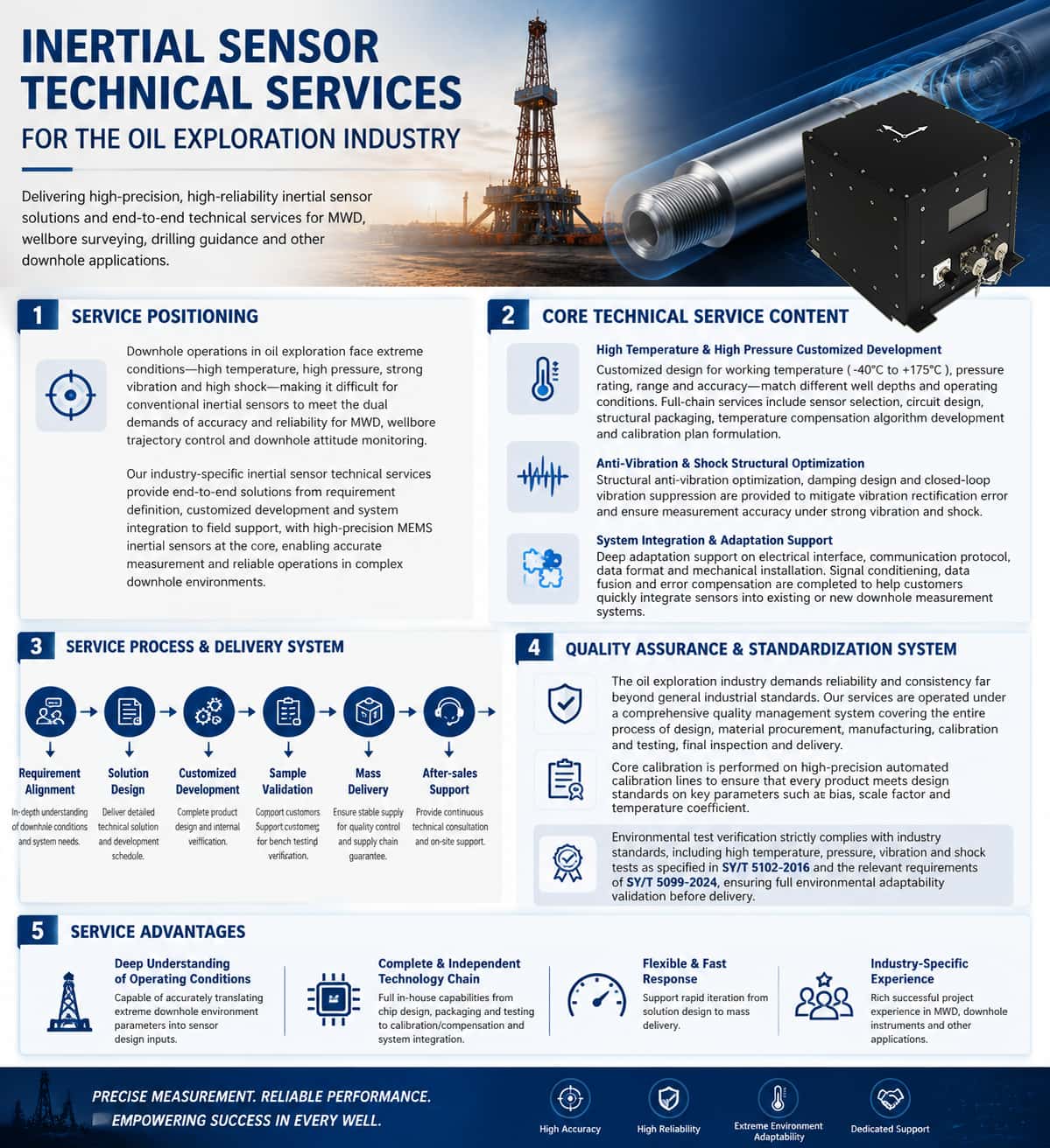
The oil and gas industry places unique and rigorous demands on inertial sensors. Whether for Measurement While Drilling (MWD), wellbore trajectory control, or downhole attitude monitoring, IMU sensors perform indispensable core measurement functions. However, downhole environments are characterized by extreme conditions—including high temperatures, high pressures, intense vibrations, and severe shocks—while varying well conditions, depths, and bottom-hole assemblies (BHAs) impose distinct requirements regarding sensor performance, dimensions, interfaces, and operating temperature ranges. Standard off-the-shelf products often fail to fully meet specific operational needs, making customized development the norm within the inertial sensor supply chain for this industry. Meanwhile, the lifecycle of oil and gas exploration equipment—from R&D to mass production—follows a typical trajectory: customized development, small-batch prototyping, and volume supply. This process reflects both the industry's uncompromising pursuit of product quality and reliability and the unique role inertial sensors play as critical components within supply chain management. These three stages are detailed below. 1. Customized Development: Application-Driven, Deeply Tailored Solutions Customized development of inertial sensors for the oil and gas industry essentially involves translating the specific downhole operational requirements of the client into engineered sensor solutions. Requirement Alignment and Solution Design. Customized development begins with a deep understanding of the client's application scenario—including well depth and temperature ranges, downhole pressure ratings, drill string vibration and shock profiles, installation space and interface constraints, measurement accuracy requirements, and communication protocols and data formats. Sensor manufacturers must be capable of rapidly responding to customization requests, particularly for specialized needs such as wide measurement ranges, vibration resistance, high-shock tolerance, and extended temperature ranges. The design phase encompasses system-level tasks—such as sensor selection, circuit design, structural design, thermal management, and vibration-resistant design—culminating in the delivery of a detailed technical proposal and development timeline. Independent Control of Core Technologies. The customized development of high-performance inertial sensors involves multiple technical stages, including structural design, ASIC circuit design, packaging and testing, and calibration and compensation. Possessing fully proprietary structural architectures and rapid customization design methodologies serves as the technical foundation for quickly meeting client-specific requirements. Meanwhile, autonomous and controllable packaging and testing lines, along with automated batch calibration assembly lines, lay the foundation for consistency, yield rates, and production capacity during the customization phase, paving the way for subsequent mass production. Design Verification and Iteration. Customized development is not a one-off delivery but a closed-loop process involving multiple rounds of design, verification, and iteration. Sensor performance, structure, and algorithms are continuously optimized based on test data and field application feedback from the customer until all operational requirements are fully met. 2. Small-Batch Prototyping: A Bridge Between Design and Physical Product Small-batch prototyping is a critical link connecting customized design with mass production; its core value lies in "verifying the highest risks at the lowest cost." Purpose and Scope of Prototyping. Small-batch prototyping typically involves producing a limited number of units (ranging from a few to several dozen) prior to formal mass production. These samples are used by customers for integration testing, downhole field verification, and system-level commissioning. The prototyping phase entails completing the full assembly, calibration, testing, and burn-in processes to ensure the samples accurately represent the performance standards of the final mass-produced units. For downhole oil and gas applications, prototypes must also undergo environmental reliability testing, such as high-temperature/high-pressure tests and vibration/shock tests. Rapid Iteration and Engineering Optimization. The small-batch prototyping phase often involves design fine-tuning and optimization—such as minor structural dimension adjustments, temperature compensation algorithm tweaks, or changes to interface definitions. The ability to respond quickly during this stage directly determines the project's overall timeline. Manufacturers with comprehensive R&D, production, and testing systems can ensure seamless, rapid transitions from conceptual design and sample testing to volume supply. Transition Management from Prototyping to Mass Production. Small-batch prototyping serves not only as technical verification but also as a trial run for production processes. Small-batch production allows for the early identification of potential bottlenecks in manufacturing, testing, and the supply chain, ensuring thorough preparation for subsequent volume supply. 3. Volume Supply: Quality Systems and Supply Chain Assurance Volume supply represents the final delivery stage of customized development and serves as the ultimate test of an inertial sensor supplier's comprehensive capabilities within the oil and gas industry. Quality Management System. The oil and gas industry imposes quality management system requirements on suppliers that far exceed those of general industrial sectors. API Q1 is a quality management system standard specific to the oil and gas industry, introduced by the American Petroleum Institute (API); it is more rigorous than ISO 9001. The API Q1 specification covers the entire process—from design and production to the supply chain—requiring organizations to demonstrate their ability to consistently provide reliable products. For inertial sensor manufacturers, establishing and operating an API Q1 quality management system represents a pivotal leap from merely being "capable of manufacturing" to "delivering reliable performance." Supply Chain Management. During the mass supply phase, sensor manufacturers must establish stable raw material supply channels, controllable outsourced processing resources, and efficient logistics and delivery systems. Ancillary materials—such as specific inertial sensors, chassis, housings, PCBs, and various electronic components—are often procured externally, necessitating strict supplier qualification audits and quality control. Core processes—including high/low-temperature sensor calibration, error compensation, performance testing, and assembly/debugging—are performed independently by the manufacturer, leveraging their own technical strengths. Batch Calibration and Consistency Control. The accuracy of inertial sensors depends not only on the chip itself but, more importantly, on the precision of calibration and compensation. During mass supply, manufacturers require fully in-house developed automated batch calibration lines. By combining proprietary equipment structures and fixtures with optimized calibration algorithms and communication architectures, they can ensure that every product meets performance standards while achieving high-volume output. The consistency and repeatability of mass-produced products regarding key metrics—such as bias, scale factor, and temperature coefficients—serve as critical benchmarks for evaluating mass supply capabilities. Summary The lifecycle of inertial sensors for the oil and gas industry—spanning custom development, small-batch prototyping, and mass supply—forms a complete value chain connecting market demands to finished products. Custom development translates downhole operating conditions into product specifications; small-batch prototyping mitigates technical risks through physical verification; and mass supply relies on quality management systems and supply chain capabilities to ensure reliable delivery. For manufacturers, possessing both robust technical expertise and comprehensive service capabilities is essential; these factors constitute the industry's entry threshold and core competitiveness.
Read More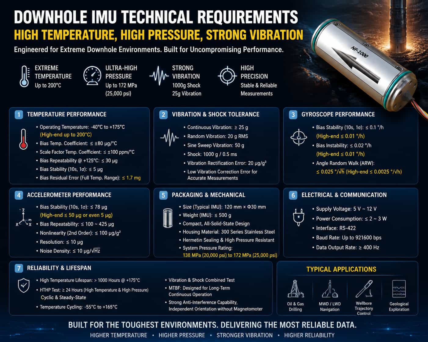
I. Introduction In downhole operations such as oil drilling and geological exploration, Inertial Measurement Units (IMUs) perform core functions including wellbore trajectory control, Measurement While Drilling (MWD), attitude determination, and navigation/positioning. However, the downhole environment is a "purgatory" for sensors: temperatures can exceed 150°C or even 200°C, pressures surpass 100 MPa, and the drill string is subjected to continuous, intense vibration and high-impact loads. In such environments, conventional IMU sensors are highly susceptible to accuracy drift, reduced service life, and even total failure. Therefore, defining the rigorous technical specifications for IMU sensors operating in high-temperature, high-pressure, and high-vibration downhole environments is crucial for ensuring the safety and accuracy of drilling operations. The technical specifications for downhole IMU sensors can be categorized into six key dimensions: temperature adaptability, vibration and shock tolerance, accuracy and stability, packaging and dimensional constraints, electrical and power characteristics, and operational life and reliability. These are detailed below. II. Temperature Adaptability Specifications Temperature represents the most severe challenge posed by the downhole environment to IMU sensors. The global geothermal gradient is generally 25°C per kilometer of depth; in ultra-deep wells, bottom-hole temperatures often exceed 150°C. Consequently, the operating temperature range is a primary technical specification. Operating Temperature Range: Downhole IMU sensors typically require an operating temperature range of -40°C to +125°C, while high-end products must withstand -40°C to +175°C or higher. Some sensors designed for ultra-deep wells can already tolerate extreme temperatures of 180°C to 200°C. The lower limit of the operating temperature range cannot be overlooked either, as equipment must withstand low temperatures during operations in cold regions or winter conditions. Full-Temperature-Range Compensation and Temperature Stability: Merely having the capability to operate across a wide temperature range is insufficient to meet accuracy requirements. Sensors must undergo precision compensation across the entire temperature range to ensure low drift and high repeatability despite extreme temperature fluctuations. Key specifications include: the bias temperature coefficient typically needs to be controlled within ±80 μg/°C, and the scale factor temperature coefficient within ±100 ppm/°C. In a high-temperature environment of +125°C, the accelerometer's bias repeatability must be controlled within 30 μg, and its bias stability (10-second 1σ) must be less than 5 μg. Residual bias error across the temperature range is a key parameter for assessing temperature adaptability; high-end products can keep this within 1.7 mg. III. Vibration and Shock Tolerance Specifications During rotary drilling, the downhole drill string is subjected to continuous wide-band random vibration and instantaneous, intense shocks caused by the drill bit breaking rock. This represents the second major challenge for IMU sensors. Continuous vibration tolerance: Sensors must withstand continuous vibration environments, typically requiring tolerance for continuous vibration exceeding 25g (gravitational acceleration). Under random vibration conditions, some high-performance sensors have successfully undergone combined testing involving 20g RMS random vibration and 50g sinusoidal swept-sine vibration. Instantaneous shock tolerance: Drill bit impacts generate extremely high peak instantaneous accelerations; sensors must withstand high-intensity shocks in the range of 1000g/0.5ms. This specification directly determines the sensor's survivability under harsh operating conditions. Vibration suppression capability: Beyond merely "withstanding" vibration, sensors must also "suppress" the impact of vibration on measurement accuracy. Vibration rectification error is a critical factor; advanced closed-loop architectures can reduce this error tenfold, achieving a vibration suppression capability of 20 μg/g². Low vibration rectification error ensures that true gravity and angular velocity signals can be clearly extracted amidst the complex vibrations of the drill string. IV. Accuracy and Stability Specifications While meeting environmental adaptability requirements, IMU sensors must also possess sufficient measurement accuracy; otherwise, attitude determination and trajectory control would be meaningless. Gyroscope specifications: Gyro bias stability is a core parameter for measuring gyroscope accuracy. Requirements are typically below 0.1°/h (10-second 1σ), with high-end products achieving 0.01°/h or even lower. Bias instability requirements are below 0.02°/h, with some products achieving levels within 0.01°/h. Angle Random Walk (ARW) is a critical metric for gyro noise levels; requirements start as low as 0.025°/√h, with high-end products achieving 0.0025°/√h. Accelerometer specifications: Bias stability requirements are typically below 78 μg, with high-performance products achieving less than 50 μg or even 5 μg (10-second, 1σ). Bias repeatability must be controlled within the 100 μg to 425 μg range. The second-order nonlinearity coefficient must be less than 100 μg/g² to ensure linearity in acceleration measurements across a wide dynamic range. Regarding resolution, high-performance accelerometers can achieve levels below 10 μg. Noise density, a key indicator of the accelerometer's noise floor, is typically required to be below 10 μg/√Hz. Long-term stability: Given that downhole operations can span weeks or even months, the long-term stability of sensor bias and scale factor is crucial. The combined monthly repeatability for bias must be controlled within 150 μg, and for scale factor, within 150 ppm. The combined monthly repeatability for the nonlinearity coefficient must be controlled within ±40 μg/g². V. Packaging and Dimensional Constraints Downhole space is extremely limited; IMU sensors must meet strict miniaturization and packaging requirements. Physical dimensions: Sensors require a compact design to fit into downhole tools with limited diameters. A typical high-performance IMU measures approximately 120 mm × Φ30 mm. Discrete components, such as accelerometers, require even greater miniaturization, with typical dimensions as small as Φ18.2 × 16 mm. Weight: Lightweight design is a standard requirement for downhole instruments. The weight of a complete IMU is typically kept under 500 g, while discrete accelerometers can weigh as little as 25 g. Structural design: An all-solid-state design with no moving parts is the preferred choice for downhole IMUs, significantly enhancing reliability in environments subject to intense vibration and high shock. An integrated cylindrical design facilitates embedding into downhole tools without altering existing equipment layouts. The housing must be constructed from corrosion-resistant, high-strength materials, such as 300-series stainless steel. Sealing and Pressure Resistance: As a core component of downhole instruments, the IMU sensor requires packaging that meets high-pressure sealing standards. Although the IMU is typically housed within a pressure-resistant tool string, its packaging design must still ensure airtight integrity and insulation performance in high-temperature, high-pressure environments. System-level pressure resistance specifications typically require ratings of 138 MPa (20,000 psi) or even 172 MPa (25,000 psi). VI. Electrical and Power Consumption Specifications Downhole power supply conditions are limited; therefore, the electrical characteristics of the IMU sensor directly impact system feasibility and operational duration. Supply Voltage: Must support a wide input voltage range to accommodate unstable downhole power conditions; typical requirements range from 5V to 12V. Power Consumption: Low power consumption is a critical requirement. The power consumption of the complete IMU unit generally needs to be kept within 2W to 3W. Low power consumption not only alleviates the load on the downhole power supply system but also minimizes the sensor's own temperature rise, facilitating thermal management in high-temperature environments. Communication Interface: Must be equipped with a bus interface suitable for long-distance downhole transmission; RS-422 is a common choice. The communication baud rate must meet real-time requirements, typically reaching up to 921,600 bps. The data refresh rate must satisfy the control system's real-time needs, with a typical value of no less than 400 Hz. VII. Operational Life and Reliability Specifications Downhole operations cannot be arbitrarily interrupted; therefore, the IMU sensor must possess sufficient operational life and reliability. High-Temperature Operational Life: The sensor must be capable of continuous operation for several thousand hours at its rated operating temperature. At the extreme operating temperature of +175°C, a service life exceeding 1,000 hours is required. Reliability Testing: The sensor must pass a series of environmental reliability tests, including High-Temperature High-Pressure (HTHP) cycling and steady-state tests (typically ≥24 hours), temperature cycling tests (e.g., -55°C to +165°C), and combined high-temperature vibration tests. Mean Time Between Failures (MTBF) serves as a quantitative measure of reliability and must meet the requirements for continuous downhole operation. Anti-interference capability: In downhole environments characterized by strong magnetic interference, the IMU must possess the ability to orient itself autonomously—independent of the Earth's magnetic field—thereby overcoming the failure issues faced by traditional magnetic compasses in ferromagnetic environments (such as inside steel casings). Conclusion The technical specifications for downhole IMUs—designed to withstand high temperatures, high pressures, and intense vibrations—encompass six key dimensions: temperature adaptability, tolerance to vibration and shock, measurement accuracy and stability, package size, electrical power consumption, and operational lifespan/reliability. These parameters are interconnected and mutually constraining. Industry trends indicate a continuous rise in upper operating temperature limits—moving from 125°C toward 150°C, 175°C, and even 200°C—alongside ongoing improvements in vibration suppression and measurement accuracy, as well as optimized miniaturization and low-power designs. These technological advancements are driving the evolution of downhole IMU sensors toward higher temperature and vibration tolerance, greater accuracy, and extended service lives, thereby providing increasingly robust technical support for the exploration and development of deep-earth oil and gas resources.
Read More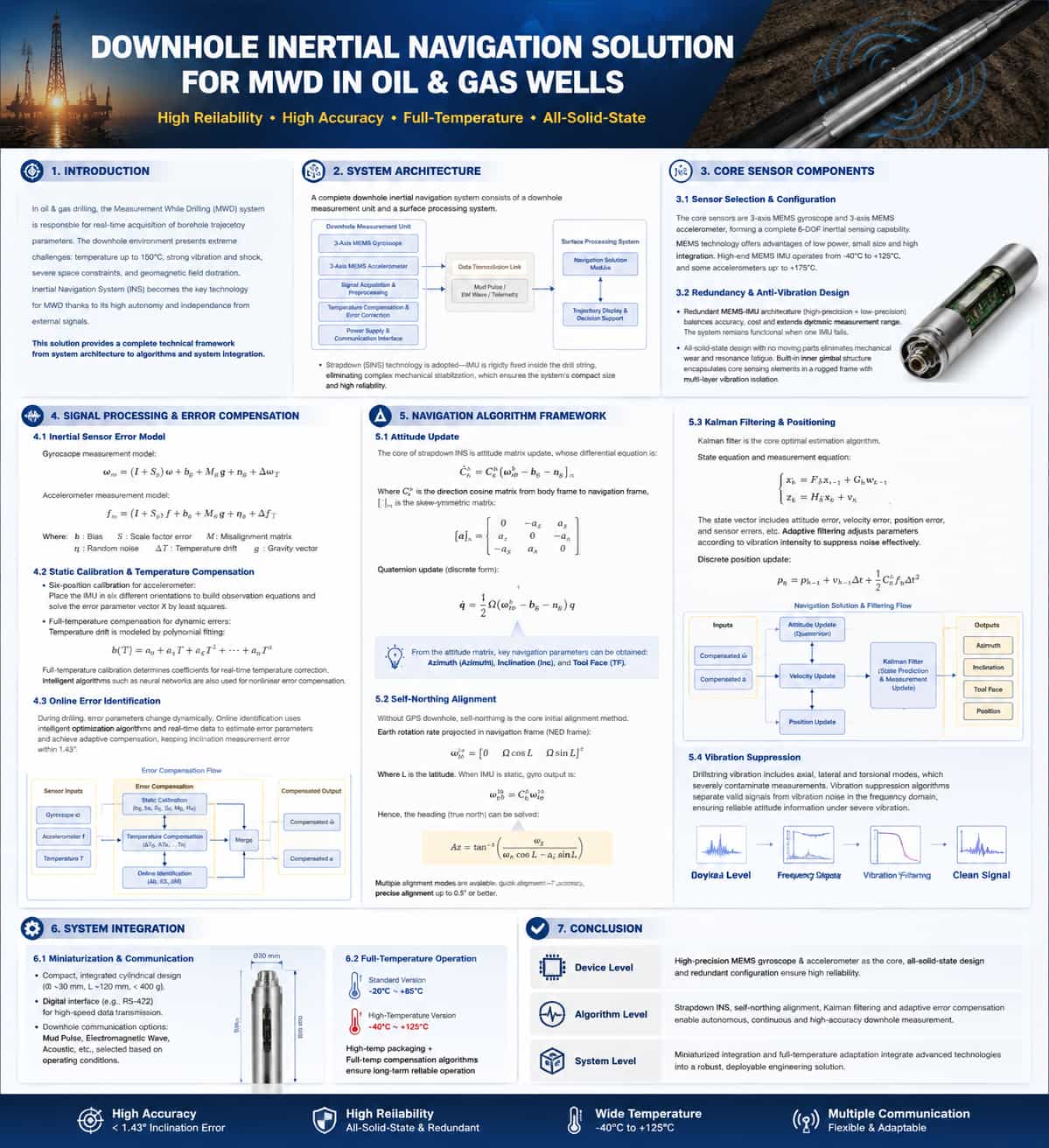
Introduction In oil and gas drilling engineering, Measurement While Drilling (MWD) systems perform the critical task of acquiring real-time borehole trajectory parameters. The downhole environment imposes extremely rigorous demands on navigation systems—including temperatures exceeding 150°C, continuous intense vibration and shock, severe spatial constraints, and significant geomagnetic field distortion—all of which create technical barriers for downhole navigation. Inertial Navigation Systems (INS) have emerged as a key technical approach for MWD due to their high level of autonomy and independence from external signals. This paper provides a technical analysis covering five aspects: system architecture, core components, error compensation, navigation algorithms, and system integration. System Architecture A complete inertial MWD system consists of a downhole measurement unit and a surface processing system. The downhole unit is installed within a drill collar near the drill bit and integrates an Inertial Measurement Unit (IMU)—comprising tri-axial gyroscopes and tri-axial accelerometers—along with signal acquisition circuitry, a power module, and communication interfaces. The surface system is responsible for data reception, navigation computation, borehole trajectory visualization, and decision support. Current mainstream solutions employ strapdown inertial measurement technology, in which the IMU is rigidly mounted inside the drilling tool. By eliminating complex mechanical stabilization structures, this approach fundamentally enables system miniaturization and enhances reliability. Core Sensor Components Sensor Selection and Configuration The core sensors of the LWD (Logging While Drilling) inertial navigation system consist of a tri-axial MEMS gyroscope and a tri-axial MEMS accelerometer, providing comprehensive six-degree-of-freedom inertial sensing capabilities. MEMS technology has become the mainstream choice due to advantages such as low power consumption, compact size, and high integration potential. High-end MEMS IMUs operate within a temperature range of -40°C to +125°C, with some accelerometers capable of withstanding temperatures up to +175°C. Redundant Configuration and Vibration-Resistant Design Redundant MEMS-IMU configuration is a key method for enhancing reliability. A typical dual-inertial-navigation architecture incorporates both high-precision and low-precision IMUs, balancing accuracy and cost while extending the dynamic measurement range. The system remains functional even if one sensor unit fails. Regarding vibration resistance, the fully solid-state design contains no moving mechanical parts, fundamentally eliminating mechanical wear and resonance-induced fatigue. An internal platform structure encases the core sensing elements within a robust mount, utilizing a multi-layer design to absorb and dampen vibration energy. Signal Processing and Error Compensation Inertial Sensor Error Models Measurements from MEMS inertial sensors contain various error components. The gyroscope measurement model is: ω̃ = ω + b_g + s_g∙ω + M_g∙ω + n_g + ε_g(T) The accelerometer measurement model is: ã = a + b_a + s_a∙a + M_a∙a + n_a + ε_a(T) + g Where: "b" = bias; "s" = scale factor error; "M" = installation error matrix; "n" = random noise; "ε(T)" = temperature drift; "g" = gravitational acceleration vector. Achieving high-precision measurement requires the calibration and compensation of each error term. Static Calibration and Temperature Compensation Static error compensation is performed during the factory calibration phase. Taking the six-position calibration of an accelerometer as an example, observation equations—$y = H \cdot X + v$—are established by placing the IMU in six different orientations. The error parameter vector $X$ is then solved using the least-squares method. Full-temperature-range compensation is critical for dynamic compensation. Polynomial fitting models are commonly used to characterize temperature drift: $\varepsilon(T) = k_0 + k_1 T + k_2 T^2 + \dots + k_n T^n$ Fitting coefficients ($k_0, k_1, \dots, k_n$) are determined through full-temperature-range calibration experiments to enable real-time temperature correction. In recent years, intelligent algorithms—such as neural networks—have also been introduced to efficiently compensate for nonlinear errors. Online Error Identification Error parameters change dynamically during the drilling process, a scenario that traditional offline calibration struggles to address. Online error identification utilizes intelligent optimization algorithms and real-time data to dynamically identify error parameters and achieve adaptive compensation, thereby keeping the borehole inclination measurement error within 1.43°. The complete error compensation process is as follows: 5. Navigation Algorithm Framework 5.1. Attitude Update The core of strapdown inertial navigation computation is the update of the attitude matrix; its differential equation is: Let be the attitude transformation matrix from the carrier frame to the navigation frame.The skew-symmetric matrix of the vector: The discretization solution employs a quaternion update algorithm, and the quaternion differential equation is: Three key navigation parameters—azimuth, inclination, and tool face angle—can be extracted from the attitude matrix. 5.2. Self-North-Seeking Initial Alignment In the absence of GPS signals downhole, self-north-seeking serves as the core technology for initial alignment. The projection of the Earth's angular velocity of rotation onto the navigation frame (North-East-Up coordinate system) is: ,corresponds to the local latitude. When the IMU is stationary, the gyro output is: From this, the heading angle (relative to true north) is calculated: The system offers multiple alignment modes: rapid alignment with an accuracy of approximately 1°, and precision alignment achieving 0.5° or better. 5.3. Kalman Filtering and Positioning Kalman filtering is the core optimal estimation algorithm for the inertial navigation system; the state and observation equations are as follows: The state vector comprises attitude errors , velocity errors, position errors, and sensor errors. To address the downhole vibration environment, adaptive filtering is employed; parameters are dynamically adjusted based on vibration intensity to effectively suppress noise. The discrete position recursion formula is:
Read More
A gyro north-finder is an inertial measurement device that utilizes the gyroscopic effect to sense the Earth's angular velocity of rotation, thereby autonomously determining the direction of true north. Unaffected by external magnetic fields and independent of satellite signals such as GPS, it provides a stable and reliable azimuth reference under harsh conditions—including environments with strong electromagnetic interference, underground spaces, and polar regions. Its core operating principle involves using a high-precision gyroscope to sense the Earth's rotational angular velocity vector; the angle between the carrier's reference axis and true north is then calculated and output as azimuth information. This article presents a systematic comparative analysis of gyro north-finders across four dimensions: accuracy definitions, technical standards, application scenarios, and key selection criteria. I. Accuracy Definitions: From Core Metrics to Comprehensive Evaluation Systems Regarding accuracy definitions, north-finding accuracy is expressed as a 1σ standard deviation, measured in degrees or arcseconds. A comprehensive evaluation should encompass absolute north-finding error, repeatability, circular linearity, and attitude measurement error. Fiber-optic north-finders can achieve static accuracy levels of 0.02° or even 0.001°; leveraging the Sagnac effect and all-digital closed-loop control, their bias instability can be as low as 0.002°/h. The performance of MEMS north-finders has improved significantly in recent years; high-end products have achieved bias instability better than 0.02°/h, with typical north-finding accuracy ranging from 0.5° to 1° (e.g., the Maixinminwei NF1100 achieves ≤1°×sec(L), while the NF1200 reaches 0.5°×sec(L)), and some miniature products can achieve 0.25° accuracy within three minutes. Fiber-optic solutions lead in absolute accuracy, whereas MEMS solutions offer advantages in size and cost. II. Technical Standards: A Multi-Level System Spanning Military Specifications to National Standards The technical standard system for gyro north-finders encompasses multiple levels—including national military standards, industry standards, and national standards—providing a comprehensive framework for product design, manufacturing, testing, and acceptance. Both fiber-optic and MEMS gyro north-finders must adhere to the requirements of this standard system; compliance is particularly stringent in the military sector, where the relevant standards carry greater mandatory force. At the national military standard level, GJB 2863A-2015, *General Specification for Gyro North-Finders*, serves as the guiding document. It stipulates general requirements, detailed requirements, and quality assurance provisions, acting as the fundamental basis for the development and production of all military-grade north-finders. At the national standard level, GB/T 45570-2025, *General Technical Requirements for Optical Gyroscopes*, is the latest released national standard. It covers product classification, technical requirements, test methods, and specifications for marking and packaging regarding fiber-optic gyroscopes and laser gyroscopes. Its Appendix B provides reference data on key performance indicators for typical fiber-optic gyroscope products, serving as a crucial technical basis for the design, production, and acceptance of fiber-optic north-finders. Additionally, some enterprises manage production in accordance with quality system standards such as ISO 9001:2008. At the gyroscope component level, GJB 10024-2021, *Test Methods for MEMS Gyroscopes*, specifies the test conditions, items, and methods for MEMS gyroscopes; it applies to functional and performance testing of MEMS gyroscopes used in inertial navigation, guidance, and control systems. GJB 8898-2017, *General Specification for Fiber-Optic Gyroscopes*, specifically standardizes the performance requirements and test methods for fiber-optic gyroscopes. III. Application Scenarios: Cross-Domain Applications Ranging from the Battlefield Frontline to Underground Engineering Gyro north-finders are applied across both military and civil sectors, covering a wide range of operational conditions—from static, high-precision referencing to dynamic, real-time orientation. Due to differences in performance characteristics and structural design, MEMS north-finders and fiber-optic gyro north-finders have distinct application scenarios. In the military sector, gyro north-finders are core equipment for the rapid and covert orientation of weapon systems. With their arc-second-level static accuracy, fiber-optic north-finders are widely used for high-precision alignment tasks involving artillery, missile launchers, radar antennas, and naval inertial navigation systems. Leveraging advantages such as compact size, low power consumption, and rapid startup, MEMS north-seeking instruments are seeing significantly increased application on lightweight weapon platforms. They facilitate rapid pre-launch alignment for missiles, rockets, artillery, and UAVs, and can even be embedded in handheld soldier terminals, underwater vehicles, and guided munition platforms—scenarios where fiber-optic solutions are difficult to implement. In environments characterized by electromagnetic interference or GPS denial, the fully autonomous and interference-resistant nature of MEMS north-seeking instruments makes them an ideal tool for covert orientation in mobile weapon systems. In the civil sector, fiber-optic north-seeking instruments are primarily used for directional control in tunnel shield tunneling, providing a stable true-north reference deep within tunnels where GPS signals are unavailable. In oil and gas exploration, they are installed near the drill bit to measure borehole azimuth and inclination in real-time; serving as a key technology for directional drilling, they achieve an accuracy of approximately ±0.1°. In geodesy and precision engineering, these instruments provide high-precision azimuth references for total stations and laser trackers, and are used for deformation monitoring of structures such as bridges and dams, achieving static accuracy of ≤0.02°. Thanks to their cost-effectiveness, miniaturization, and low power consumption, MEMS north-seeking instruments provide reliable orientation and attitude control in GPS- or magnetometer-free environments like coal mine tunneling and general mining operations; additionally, integrated MEMS systems can achieve a heading accuracy of 0.25° in railway trains. Overall, MEMS technology enables smaller, lighter north-seeking instruments that meet the needs of most civil industries with mid-to-high-level accuracy, making them particularly suitable for fields with constrained surveying environments. Regarding environmental adaptability, fiber-optic north-seeking instruments are sensitive to temperature fluctuations and bulky, requiring drift compensation when significant temperature gradients exist underground. Conversely, MEMS north-seeking instruments offer vibration and shock resistance and compact integration capabilities, though their high-temperature tolerance is limited to approximately 85°C. Consequently, fiber-optic solutions hold the advantage in scenarios involving continuous high-temperature downhole drilling. IV. Key Selection Considerations: A Comprehensive Trade-off Analysis When selecting between MEMS and fiber-optic north-seeking instruments, one must weigh multiple factors—including accuracy requirements, operating environments, dynamic characteristics, size and weight, cost budgets, and integration capabilities—as priorities vary significantly depending on the application scenario. Accuracy requirements dictate the technology choice: For high-precision applications requiring accuracy of ≤0.1°—such as shipborne inertial navigation system alignment or the establishment of high-precision geodetic benchmarks—fiber-optic north-seeking instruments are typically the only option, offering static accuracy of 0.02° or even 0.001°. Conversely, if the required accuracy falls between 0.2° and 1.0° and cost-sensitivity is a factor, MEMS is the superior choice; some MEMS products offer rapid alignment within 30 seconds (1° accuracy) or precise alignment within 90 seconds (0.5° accuracy), demonstrating clear advantages in dynamic response. Size, weight, and power consumption are increasingly critical factors in modern applications. MEMS north-seeking instruments can be miniaturized to approximately 40mm cubes, weighing less than 70g with power consumption as low as 1.5W, making them ideal for payload-sensitive platforms such as individual soldier equipment. Traditional fiber-optic instruments are significantly larger and consume more power; despite recent optimizations, they still lag orders of magnitude behind MEMS in these areas, making MEMS virtually the only viable technology for space-constrained applications. · Environmental adaptability is another key selection factor. MEMS north-seeking instruments offer superior vibration and shock resistance, making them suitable for dynamic platforms like vehicles and aircraft; neither technology is susceptible to magnetic field interference. Fiber-optic solutions hold the advantage in high-temperature environments (lacking semiconductor temperature limitations), making them particularly suitable for continuous high-temperature downhole drilling. While MEMS devices have slightly lower high-temperature tolerance, both technologies generally cover an operating temperature range of -40°C to +80°C. · Mechanical structure and indexing mechanisms also directly influence the selection decision. Fiber-optic north-seeking instruments utilize a single-axis gyroscope combined with a mechanical indexing mechanism; while they offer high static accuracy, their dynamic performance is limited, and they are prone to drift under vibration. In contrast, MEMS north-seeking instruments typically employ a three-axis strapdown configuration that eliminates the need for indexing mechanisms, resulting in superior dynamic response and vibration resistance; meanwhile, some low-cost single-axis MEMS models achieve cost reductions while maintaining accuracy through rotational modulation techniques. · Cost considerations are crucial during the selection process. Fiber-optic north-seeking instruments entail high initial procurement costs, with high-end models reaching hundreds of thousands of yuan. Conversely, MEMS north-seeking instruments benefit from semiconductor mass-production processes, offering significantly lower costs for equivalent accuracy. If accuracy requirements are not overly stringent and cost is the primary constraint, MEMS technology offers a clear economic advantage. Both technologies feature all-solid-state designs with manageable maintenance costs; however, MEMS devices offer higher levels of integration and typically exhibit lower failure rates. · Integration capabilities and communication interfaces represent key technical details in the selection process. Mainstream gyro north-seeking instruments support serial interfaces such as RS422, RS232, and CAN, with data output frequencies typically ranging from 100 Hz to 200 Hz; users should ensure compatibility with their host system's interface types and data protocol requirements. Regarding GNSS integration, some high-end products offer PPS synchronization input and TOV output functions, enabling time synchronization between inertial data and external satellite receivers. Selecting a gyro north-seeking instrument is a systematic process involving considerations of accuracy, cost, operating environment, dynamic characteristics, and integration. The MEMS and fiber-optic technological paths each possess distinct core advantages and operational limits; neither is inherently superior to the other. Users should conduct a comprehensive assessment of their mission requirements to strike an optimal balance between these two approaches: for strategic-level applications prioritizing maximum accuracy regardless of cost, fiber-optic north-seeking instruments remain the irreplaceable choice; for tactical-level and civilian scenarios prioritizing miniaturization, rapid response, and cost-effectiveness, MEMS north-seeking instruments offer a more pragmatic and flexible solution. As MEMS gyroscope accuracy continues to improve and fiber-optic gyroscope miniaturization technology advances, the boundaries between these two technologies are becoming increasingly blurred. Future selection decisions will likely focus more on the specific constraints of the mission scenario rather than on technological labels alone—a shift that will undoubtedly provide end-users with a wider range of options and superior cost-performance value.
Read More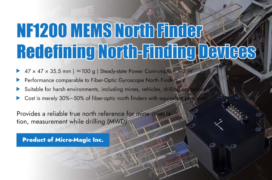
In the field of high-precision directional measurement, fiber optic gyroscopes and laser gyroscope north finders have long dominated. Although they have considerable accuracy, their large size, high power consumption, and expensive manufacturing costs make it difficult for many applications that are sensitive to weight, power supply, and budget to truly enjoy high-precision north finding services. The emergence of NF1200 high-precision MEMS north finder launched by Micro-Magic Inc is attempting to break this situation. The first characteristic of this product is small . The external dimensions of NF1200 are only 47×47×35.5mm, weighing about 100 grams, with a steady-state power consumption of no more than 2 watts and a startup time of no more than 2 seconds. In contrast, traditional fiber optic north finders typically have a volume of over 100mm, a weight of over 500 grams or even up to 2 kilograms, and power consumption ranging from 5 to 15 watts. This level of difference means that NF1200 can easily be embedded in small unmanned aerial vehicles, individual handheld terminals, small autonomous underwater vehicles, and projectile guidance platforms that are extremely demanding on load and power supply, while fiber optic solutions are almost impossible to achieve. The second characteristic is accuracy. Many people's impression of MEMS gyroscopes still remains at the stage of low precision and large drift, but the performance parameters of NF1200 have overturned this cognition. The zero bias instability of its MEMS gyroscope is better than 0.02°/h, and the angle random walk is better than 0.01°/√ h. The system level self north finding accuracy reaches ≤ 0.5°secL (L represents local latitude), and the attitude accuracy is better than 0.05°. This means that NF1200 has reached the same level of north finding accuracy as fiber optic solutions, truly achieving high-precision north finding tasks that were previously only possible with optical gyroscopes using MEMS technology. The third characteristic is stability. NF1200 provides complete compensation for zero position, scale factor, non orthogonal errors, and acceleration related errors within the range of -40°C to +80°C, and can withstand 500g shock and 6.06g random vibration. This enables it to maintain stable and reliable high-precision north finding performance even in harsh environments such as mines, vehicles, drilling, and launch overload. The fourth characteristic is "cost-effectiveness." The NF1200 achieves 100% domestic production of its components, with batch production costs ranging from approximately 30% to 50% of those of fiber optic north finders with the same accuracy. Additionally, it supports configurable north-seeking time and installation error angle correction, reducing the difficulty of integration and maintenance for users. This makes high-precision north seeking no longer exclusive to expensive equipment, but a practical technology that can be deployed on a large scale. In GPS-denied environments with strong magnetic interference, the NF1200 leverages its excellent performance, compact size, and low power consumption to provide a reliable true north reference for various scenarios such as mine orientation, measurement while drilling (MWD), pipeline inspection, individual soldiers, and unmanned vehicles. This enables high-precision MEMS north finding to truly move toward practical engineering applications.
Read More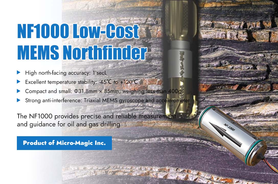
The precise control of directional drilling relies on three key parameters: inclination angle (how much the borehole is tilted), azimuth (the geographic direction the borehole faces), and tool face angle (the orientation of the directional tool). Even minor deviations in these angles can accumulate with increasing well depth, leading to significant trajectory deviations, resulting in millions of dollars in economic losses or even safety incidents. The NF1000 MEMS northfinder introduced by Micro-Magic Inc, with its advantages of low cost, compact size, high precision, and resistance to harsh environments, serves as a crucial solution to this challenge. NF1000 adopts high-performance MEMS gyroscope and accelerometer, with excellent full temperature calibration capability (-45℃ to +120℃), which can maintain stable output even in extreme underground environments. Its north finding accuracy is as high as 1°secL (L represents latitude), and its horizontal attitude accuracy is better than 0.15 °, meeting the high requirements for directional drilling in oil and gas drilling. In addition, traditional north finding equipment is often bulky and complex to install, while the NF1000 has a size of only Φ31.8mm × 85mm and weighs less than 400g, making it easy to integrate into narrow spaces such as drill rods and tunneling machines, greatly reducing installation barriers and renovation costs. In the specific application of directional drilling, NF1000 is firmly installed in the measuring short section of the downhole drilling tool assembly. If there is a fixed angle between the X-axis of NF1000 and the direction of the drill bit, the system will perform coordinate axis conversion to ensure that the output wellbore inclination angle and azimuth angle fully correspond to the true posture of the drilling tool. During the drilling process, the NF1000's built-in three-axis MEMS gyroscope continuously senses the angular velocity of the drilling tool, while the three-axis accelerometer senses the gravitational acceleration component. Real time calculation of three key data points through internal navigation algorithms: (1) Well inclination angle: ranging from 0° to 180°, used to determine whether the wellbore is vertical, inclined, or horizontal. (2) Azimuth: The angle from clockwise rotation from true north to the horizontal projection line of the wellbore determines the plane direction of drilling. (3) Tool face angle: divided into gravity tool face and gyroscope tool face. This is crucial for directional tilting and adjusting wellbore trajectories in magnetic interference environments. NF1000 represents the leading level of MEMS process inertial devices. On the underground battlefield of directional drilling in oil and gas fields, NF1000 is providing precise, resilient, and reliable guidance for every well, helping engineers reach their targets accurately in the underground maze. NF1000
Read More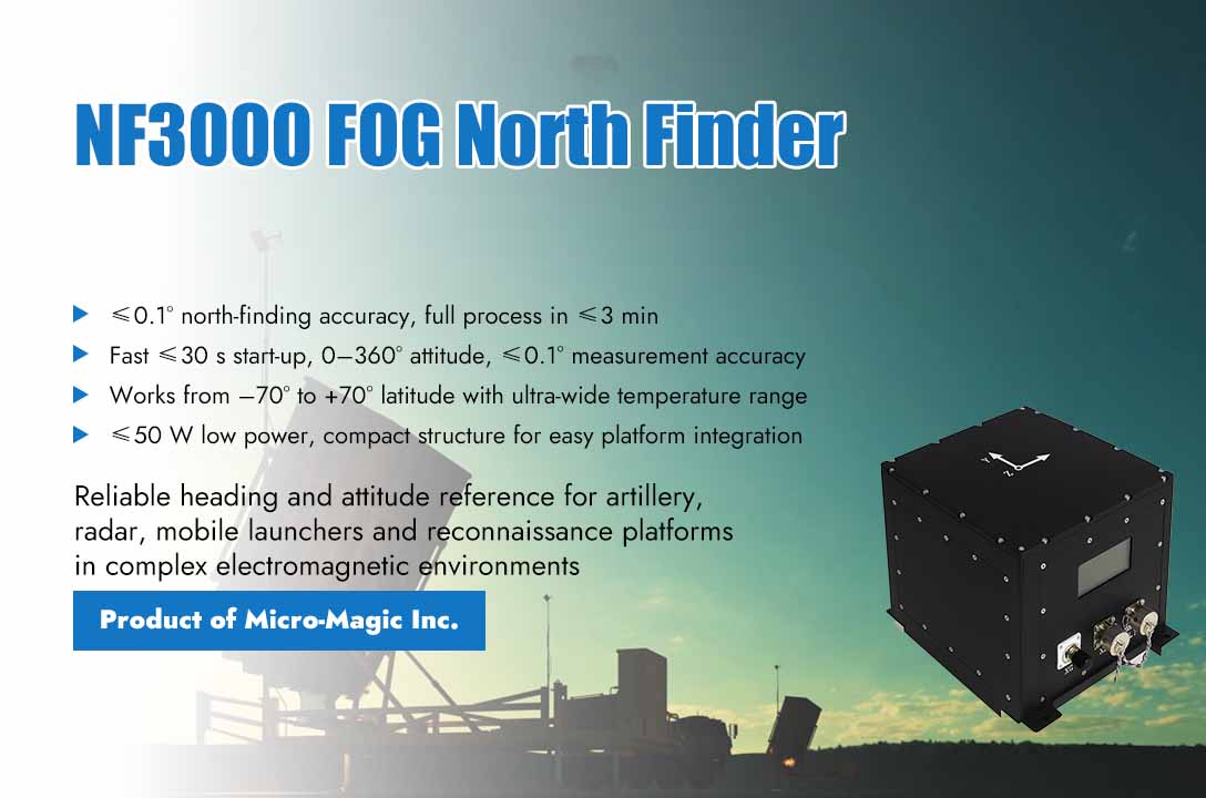
In the era of profoundly evolving modern warfare, precise and reliable autonomous orientation has become a critical determinant of battlefield success. Confronted with increasingly complex electromagnetic environments and the severe challenge of vulnerable satellite navigation systems to interference, the Fiber Optic Gyroscope (FOG) north finder, with its excellent technical performance, provides a new directional benchmark solution for various military platforms, significantly improving its combat adaptability and battlefield survival ability in extremely harsh environments. The NF3000 FOG North Finder launched by Micro-Magic Inc integrates high-precision fiber optic gyroscope and inertial measurement unit (IMU), equipped with precise indexing mechanism and advanced control calculation system. Excellent north finding accuracy of ≤ 0.1°secψhas been achieved, and the complete autonomous north finding process can be completed within 3 minutes. This performance indicator has reached the international advanced level. Its wide working latitude range covers -70 ° to+70 °, coupled with an ultra wide working temperature range, ensuring that the equipment can maintain stable and reliable operating performance in the vast majority of global regions and extreme weather conditions. NF3000 has fully considered the strict requirements of the battlefield environment in its engineering design. The exquisite structural design enables it to be easily integrated into various military equipment, while the low power consumption characteristic of ≤50W greatly enhances the battlefield applicability and sustained combat capability of the system. The high-definition OLED display screen equipped with the equipment can display key data such as azimuth, roll angle, and pitch angle in real time, and output accurate measurement results through the high-speed RS-422 interface, providing timely and reliable azimuth and attitude information support for the combat system. In extreme battlefield environments where satellite navigation is limited or completely ineffective, the NF3000 demonstrates unique combat value. Its fully autonomous north finding capability does not rely on any external signals, providing a sustained and stable position reference for command and control systems, precision strike firepower, and battlefield reconnaissance equipment. The high-precision attitude measurement capability of ≤ 0.1° and full range measurement from 0° to 360° of the equipment ensure that various combat platforms always maintain accurate orientation under complex terrain conditions. Particularly noteworthy is the NF3000's rapid start-up time of ≤30 seconds, which fully meets the stringent requirements for quick reaction capabilities in modern battlefields. Its rugged mechanical design and precision mounting interfaces, validated through rigorous environmental adaptability tests, ensure long-term operational stability under harsh conditions including intense shock and vibration. The system employs a reliable electrical connection architecture, complete with dedicated power and communication interfaces, to guarantee signal integrity even within complex electromagnetic environments. The NF3000 FOG North Finder, with its outstanding performance, provides precise and reliable autonomous orientation capabilities for various combat platforms, ensuring combat effectiveness in complex electromagnetic environments. Its fast response and stable and reliable characteristics enable military equipment to maintain precise combat capabilities even under limited satellite navigation conditions, providing solid technical support for improving the overall combat effectiveness.
Read More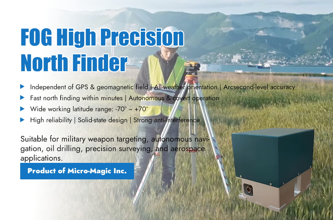
FOG North Finder is a precision instrument that utilizes the Sagnac effect of fiber optic gyroscopes to accurately and autonomously determine the true north direction (geographic North Pole direction). It does not rely on external references such as GPS, astronomical observations, or known reference points, and is not affected by geomagnetic field interference, which is its core advantage. Core Usage (1) Initial alignment and establishment of azimuth reference: This is the most important function. Provide initial orientation reference (true north direction) for various platforms or systems that require knowledge of their absolute direction. (2) Orientation maintenance and autonomous navigation: After knowing the initial position and direction, combined with sensors such as accelerometers, short-term high-precision autonomous inertial navigation can be performed, especially in GPS denied environments. Main Application Scenarios (1) Military field (core applications): ●Weapon system targeting and orientation: FOG North Finder provides fast and covert autonomous north finding for artillery, rocket launchers, and missile launch vehicles, establishing precise shooting reference directions, significantly reducing reaction time, and improving strike accuracy. Provide high-precision azimuth benchmarks for the main guns and fire control systems of tanks and armored vehicles. Provide rapid targeting for shore/ship to ship missile systems. ●Platform orientation and stability: FOG North Finder provides accurate azimuth reference for radar beam pointing of radar systems (ground, vehicle, and ship), ensuring target detection and tracking accuracy. Provide directional reference for the pointing of infrared, laser and other optoelectronic equipment in the electro-optical reconnaissance/aiming system. Provide fast alignment for large directional communication antennas. ● Initial alignment of vehicles/ships: FOG North Finder quickly determines the direction of travel reference for armored vehicles and self-propelled artillery when activated. Provide accurate initial orientation input for inertial navigation systems when submarines, surface vessels depart, float, or require recalibration. (2) Civilian field: ● Petroleum geological exploration: In the measurement while drilling, FOG North Finder is installed near the drill bit to measure the azimuth angle (combined with dip angle) of the borehole in real-time and with high precision. It is a key technology for directional drilling and horizontal drilling, greatly improving drilling efficiency and oil and gas recovery. This is a very important application in the civilian field. ● Geodetic surveying and precision engineering surveying: In areas without GPS signals or signal differences (tunnels, canyons, urban canyons, indoors), FOG North Finder provides high-precision azimuth benchmarks for measuring equipment such as total stations and laser trackers. FOG North Finder provides directional functionality for deformation monitoring systems in large-scale projects such as bridges, dams, and high-rise buildings. FOG North Finder can also establish a measurement control network independent of GPS. ● Aerospace: In the initial alignment and navigation of large drones, FOG North Finder provides the drone with a fast and autonomous takeoff reference direction, and assists in navigation in the event of GPS failure. FOG North Finder provides directional functionality for ground testing and maintenance of aircraft, especially helicopters. FOG North Finder can also assist large satellite antennas in quickly and accurately pointing. Why Does FOG North Finder Have Advantages In These Scenarios? ● Strong autonomy: completely independent of external signals (GPS, geomagnetic), can work at any location and any time. ● Strong anti-interference ability: not affected by electromagnetic interference or metal environments (compared to magnetic compasses), able to work normally in complex electromagnetic environments and near steel structures. ● Fast startup: It can usually complete the search for north within seconds to minutes, much faster than traditional gyroscopic theodolites or astronomical observations. ● High precision: Modern high-precision fiber optic gyroscope north finders can achieve north finding accuracy at the level of arcseconds or even sub arcseconds. ● High reliability and long lifespan: All solid state design, no moving parts (compared to mechanical gyroscopes), shock and vibration resistance, low maintenance requirements. ● Good environmental adaptability: able to work in a wide temperature range and harsh environments (such as high temperature and pressure underground in oil fields). Related Products Suitable For The Above Applications The series of FOG north finder produced by Micro-Magic Inc consists of fiber optic gyroscope, accelerometer, mechanical rotation control device, and embedded computer. It is a high-precision inertial instrument that can autonomously indicate azimuth by providing the angle between the carrier and true north without inputting latitude. This method based on fiber optic gyroscope and precision indexing eliminates dependence on external satellite signals (such as GPS) or known reference points, achieving true autonomous, covert, and all-weather north finding. NF2000 NF3000 NF5000 North finding accuracy (1σ) ≤ 0.5°secψ ≤ 0.02°secψ ≤ 0.05°secψ North search time ≤ 5min ≤ 5 min ≤ 3min Tilt accuracy (pitch/roll, 1 σ) ≤ 0.09 ≤ 0.02° ≤ 0.05° Range of tilt measurement -65 ~ +65 -15° ~ +15° -15° ~ +15° Range of azimuth measurement 0 ~ 360 0° ~ 360° 0° ~ 360° Working latitude range -65 ~ +65 -70° ~ +70° -70°~+70° Conclusion The core value of the fiber optic gyroscope north finder lies in providing a fast, autonomous, high-precision, and anti-interference true north direction reference. This makes it an indispensable key equipment in military weapon orientation, autonomous navigation, oil drilling, precision measurement, and other scenarios that require strict directional benchmarks and often cannot rely on external references or harsh environments. With the continuous advancement and cost reduction of FOG technology, its application in civilian fields is rapidly expanding, especially in the fields of autonomous driving, robotics, and high-end measurement. NF2000 NF3000 NF5000
Read More
The north finder is a type of compass used to find the true north direction value of a certain location. The gyroscope north finder, also known as the gyroscope compass, is an inertial measurement system that uses the principle of gyroscope to determine the projection direction of the Earth's rotational angular velocity on the local horizontal plane (i.e. true north position). Its search for north does not require external reference. Principle of Fiber Optic Gyroscope North Finder Fiber Optic Gyroscope (FOG) is a new type of all solid-state gyroscope based on Sagnac effect. It is an inertial measurement element without mechanical rotating parts, with advantages such as shock resistance, high sensitivity, long lifespan, low power consumption, and reliable integration. It is an ideal inertial device in the new generation of strapdown inertial navigation systems. In fiber optic gyroscope based north finding applications, the majority of methods used involve FOG rotation at a fixed angle and calculating the angle relative to the north direction by determining the offset. In order to accurately point north, it is also necessary to eliminate the drift of FOG. Generally, a rotating platform as shown in Figure 1 is used to place the fiber optic gyroscope on a moving base, with the plane of the moving base parallel to the horizontal plane and the sensitive axis of the fiber optic gyroscope parallel to the plane of the moving base. When starting to search north, the gyroscope is in position 1, and its sensitive axis is parallel to the carrier. Assuming that the angle between the initial direction of the sensitive axis of the fiber optic gyroscope and the true north direction is α. The output value of the gyroscope at position 1 is ω1; Then rotate the base 90° and measure the output value of the gyroscope at position 2 as ω2. Rotate 90° twice in sequence, turning to positions 3 and 4 respectively, to obtain angular velocities ω3 and ω4. Assuming the latitude of the measurement point is φ,The Earth's rotation is , The angular velocity measured at position 1 is: Where is the zero drift of the gyroscope output. Similarly, it can be concluded that: In a short period of time, assuming that the drift of the fiber optic gyroscope is a constant, that is: , Then: By using this method for measurement, the zero bias of the gyroscope can be eliminated, and there is no need to know the latitude value of the measurement location. If the latitude of the measurement location is a known value, then only measuring positions 1 and 3 (or 2 and 4) can determine the heading angle. Conclusion The fiber optic gyroscope north finder has a simple structure and excellent performance, especially able to resist impacts and various harsh environments. When the turntable is horizontal, it can provide the angle between the carrier and true north direction without inputting latitude values. In the case where the turntable is not strictly horizontal, the Earth's angular velocity measured by fiber optic gyroscope and the angle between the gyroscope and the horizontal plane measured by accelerometer are also used to calculate the angle between the baseline of the carrier and the true north direction through computer calculation. At the same time, the accelerometer can also measure the attitude angle of the north finder. NF2000 inertial navigation system High Precision FOG North Seeker NF3000 Inertial Navigation System High Performance Dynamic Fog North Seeker
Read Moreleave a message
Scan to Wechat :