
The 3D electronic compass is the core sensor component for achieving spatial orientation and attitude perception in modern AR/VR systems, and its technology is based on multi-sensor fusion for complex systems. This device can measure the absolute direction of the equipment in three-dimensional space in real time by integrating three-axis flux gate sensors, three-axis MEMS accelerometers, and/or three-axis gyroscopes. The flux gate sensor is responsible for detecting the components of the Earth's magnetic field vector on three orthogonal axes, the accelerometer senses the direction of gravity to determine pitch and roll angles, and the gyroscope provides angular velocity information for dynamic attitude compensation. This multi-sensor architecture enables electronic compasses to maintain heading accuracy in complex motion states, providing a stable directional reference for AR/VR applications. Key Technical Characteristics and Performance Parameters The performance of a 3D electronic compass directly affects the user experience of AR/VR systems. Modern devices such as C9000 series high-precision 3D electronic compass can maintain heading accuracy at extreme tilt angles of ±85°, which is achieved through three-axis accelerometers for heading compensation of a wide range of tilt angles. This anti tilt ability is particularly important for AR headsets and VR controllers, as users often experience significant head or hand movements during use. In addition, high-performance electronic compasses also use hard/soft iron calibration technology to reduce environmental interference and ensure measurement stability in metal environments. Parameter C90 C9000 The impact on AR/VR Heading range 0~360° 0~360° Full range tracking Heading accuracy 0.3~0.5° 0.2° Affects the alignment accuracy of virtual objects Tilt Angle Range Pitch ±90°; Roll 360° Pitch ±90°; Roll 360° Support large angle head rotation Tilt Angle accuracy 0.1° 0.02° Insufficient accuracy can lead to virtual object drift, screen shaking Response time 20ms 20ms Reduce virtual object latency Calibration Hard magnetic, soft magnetic, and tilt compensation Hard magnetic, soft magnetic, and tilt compensation Ensure stable and accurate orientation of virtual objects, enhance immersion, and avoid dizziness. Product Form Module/ Single-Board Module/ Single-Board Easy for secondary integration development or embedding within devices Application of 3D Electronic Compass in AR Navigation and Outdoor Exploration Virtual real registration is the core challenge of AR navigation, requiring seamless overlay of virtual navigation indicators to the correct position in the real scene. By using the azimuth, elevation, and roll angles provided by the 3D electronic compass, the system calculates the rotation matrix and translation vector of the camera coordinate system relative to the world coordinate system, and constructs a transformation matrix from the world coordinate system to the camera coordinate system, providing users with intuitive directional guidance. When the user turns on AR mode, the system captures the surrounding environment through the camera, and at the same time calls the direction data of the electronic compass and the position data of GPS to generate 3D navigation arrows that are integrated with the environment. The system can also support offline map function, relying on electronic compass and inertial navigation to continue providing directional guidance in remote areas without network signals, greatly expanding the applicability of AR navigation. Application of 3D Electronic Compass in Indoor AR Navigation and Equipment Display The indoor environment poses a serious challenge to traditional positioning technology due to the lack of GPS signals and the presence of complex magnetic interference sources. A high-precision indoor AR navigation system was constructed by combining a 3D electronic compass with IR-UWB ultra wideband positioning and image moment feature recognition. This innovative solution is the first to apply IR-UWB technology to 3D registration in augmented reality, achieving centimeter level positioning accuracy. The system consists of multiple technical modules: CMOS cameras capture real scenes; Helmet mounted displays display enhanced content; The IR-UWB module provides precise position tracking; Three dimensional electronic compass measures the viewing angle direction; Image moment feature module for identifying exhibits; Virtual scene generation module creates virtual content; The virtual real fusion module seamlessly integrates virtual content with real scenes. Application of 3D Electronic Compass in Immersive VR Experience and Virtual Gimbal The 3D electronic compass has demonstrated unique value in the field of virtual reality, especially in immersive experiences that require real directional mapping. By introducing real-world directional benchmarks into virtual environments, the electronic compass solves the problem of inconsistent direction perception in VR systems, significantly reducing users' dizziness and tendency to lose direction. In high-end VR systems, a 3D electronic compass is integrated with MEMS sensors to construct an omnidirectional tracking reference, enabling the virtual camera to accurately reproduce the true rotation angle and direction of the user's head. The virtual gimbal based on electronic compass and MEMS system represents the technological innovation of VR interactive devices. This system does not require heavy mechanical structures. It measures three-dimensional geomagnetic field data through an electronic compass, and combines MEMS accelerometer and gyroscope data to calculate the relative azimuth and attitude angle of the gimbal, as well as the zoom and focus information of the camera lens. Conclusion The core value of electronic compass in AR/VR lies in providing reliable directional reference and spatial context, and its technological evolution is driving devices to upgrade from "visual immersion" to "multi sensory collaborative interaction". With the continuous emergence of new materials, algorithms, and sensors, the role of electronic compasses in AR/VR systems will become even more important, ultimately achieving the ultimate goal of seamless integration of virtual and real worlds. C9-B C90-C C9000-A C9000-B
Read More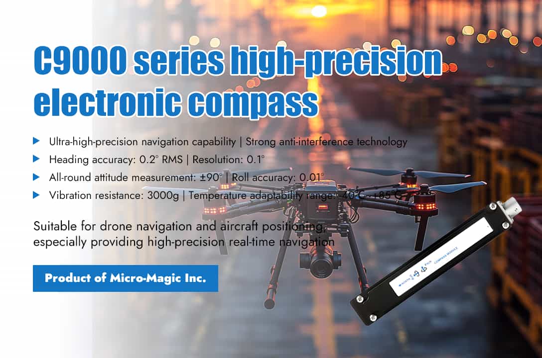
In the core field of autonomous navigation for unmanned aerial vehicles, the accuracy, reliability, and stability of direction perception directly determine the success or failure of the mission. The C9000 series high-precision six axis full attitude electronic compass launched by Micro-Magic Inc provides accurate attitude perception solutions for unmanned aerial vehicles and aircraft in all weather and terrain conditions, with military grade technical standards and industrial grade design, endowing devices with the intelligent eye of "perception direction". The C9000 series is composed of industrial grade microcontrollers with high reliability and strong anti-interference ability, high-precision tilt sensors, three-axis flux gate sensors with integrated patented technology, and driver chips. The self-developed hard and soft magnetic calibration algorithms enable the compass to eliminate the influence of magnetic fields through calibration algorithms even in environments with magnetic field interference. By integrating magnetometers for geomagnetic field measurement and accelerometers for dynamic compensation, sub-degree heading accuracy can be achieved in complex electromagnetic environments, solving the problem of attitude reference when GPS signals are obstructed. In autonomous flight of unmanned aerial vehicles, the C9000 series six axis electronic compass can correct heading drift caused by magnetic interference in real time, and use a patented tilt compensation algorithm to compensate for large range of tilt angles, ensuring flight stability and providing real-time high-precision navigation information even in extremely harsh environments. The advantages of the C9000 series high-precision compass are mainly reflected in the following aspects: 1. Ultra high precision navigation capability By capturing the horizontal component of the Earth's magnetic field through a magnetic sensor and combining it with a patented tilt compensation algorithm, heading compensation is applied to a large range of tilt angles, achieving a heading accuracy of 0.2° RMS (pitch angle <85°) and a resolution of 0.1°. In attitude tilt perception measurement, the pitch/roll accuracy reaches 0.01° (small tilt angle), supporting full attitude coverage of ± 90°. Eliminating heading angle drift caused by magnetic interference through bias tracking algorithm, and real-time solving complex motion attitude through extended Kalman filtering to ensure the stability of dynamic flight. 2. Breakthrough in anti-interference technology The three-axis flux gate sensor with integrated patented technology, combined with hard/soft magnetic adaptive calibration function, automatically adapts to changes in the surrounding magnetic field environment during operation. According to pre-set algorithms, the magnetic field data collected by the sensor is analyzed and processed, and the measurement parameters are automatically adjusted to eliminate the influence of magnetic field changes, thereby ensuring that the output heading information is always accurate and reliable. 3. Industrial grade robust design The C9000 series high-precision compass can operate in a wide temperature range, ensuring stable operation at extreme temperatures ranging from -40℃ to +85℃. The C9000 series has high resistance to vibration and impact, with a mechanical impact protection capacity of 3000g, and has passed the rigorous test of GJB150 military environmental test (high temperature/low temperature/rain/sand/vibration). Supports IP67 protection level (customizable IP68), fearless of wind, rain, sand and dust. Product performance Parameter C9000-A Compass heading parameters Heading accuracy 0.3~0.5° (RMS, pitch<85°) Resolution 0.1° Repeatability 0.05° Compass inclination parameters Pitch accuracy 0.1° Roll accuracy 0.01° (pitch<15°) 0.02° (pitch<50°) 0.05° (pitch<80°) Inclination angle resolution 0.005° Inclination range Pitch ±90°; Roll 360° Calibration Hard iron calibration Yes Soft iron calibration Yes Tilt calibration Yes Physical properties Size L125*W22*H24 (mm) Weight 110g RS-232/RS485 interface connector 5-pin aviation connector Interface features Startup delay <50ms Maximum sampling rate 50 times/second RS-232 communication rate 2400~19200 baud rate RS-485 communication optional TTL communication optional Output format hexadecimal Power supply Support voltage DC+5V (9~36V) Current (max) 40mA Working mode 30mA Environment Storage range -40℃~+125℃ Working temperature -40℃~+85℃ Vibration resistance 3000g C9000-A
Read More
Electronic compass is an important navigation tool that can provide real-time heading and attitude of moving objects. Calibration of an electronic compass is a crucial step in ensuring the accuracy of its directional measurement. 1. Calibration principle of electronic compass The electronic compass determines direction by measuring the components of the geomagnetic field. The calibration process is actually "magnetic field ellipse fitting": a) Collect magnetic field data in all directions when the device rotates. b) Generate compensation parameters by calculating hard iron interference (fixed offset) and soft iron interference (scaling and cross coupling) through algorithms. c) Automatically apply compensation during subsequent measurements to fit the magnetic field data into a sphere centered at the origin, improving directional accuracy. 2. Calibration method for electronic compass The calibration methods for electronic compasses mainly include two methods: planar calibration and three-dimensional 8-shaped calibration. (1) Plane calibration method For the calibration of the XY axis, the device equipped with a magnetic sensor will rotate on its own in the XY plane, which is equivalent to rotating the Earth's magnetic field vector around the normal passing point O(γx,γy) perpendicular to the XY plane. It represents the trajectory of the magnetic field vector projected in the XY plane during the rotation process. This can find the position of the center of the circle as (Xmax+Xmin)/2, (Ymax+Ymin)/2. Similarly, rotating the device in the XZ plane can obtain the trajectory circle of the Earth's magnetic field on the XZ plane, which can calculate the magnetic field interference vector γ (γx, γy, γz) in three-dimensional space. After calibration, the electronic compass can be used normally on the horizontal plane. However, due to the angle between the compass and the horizontal plane, this angle can affect the accuracy of the heading angle and requires tilt compensation through acceleration sensors. (2) Stereoscopic 8-shaped calibration method Usually, when a device with sensors rotates in various directions in the air, the spatial geometric structure composed of measured values is actually a sphere, and all sampling points fall on the surface of this sphere, as shown in the following figure. a) Aerial rotation: Use calibrated equipment to perform an 8-shaped movement in the air, aiming for the normal direction of the equipment to point towards all 8 quadrants of space. By obtaining sufficient sample points, the center O(γx,γy,γz) is determined, which is the size and direction of the fixed magnetic field interference vector. b) Sample point collection: When rotating the device in various directions in the air, the spatial geometric structure composed of measurement values is actually a sphere, and all sampling points fall on the surface of this sphere. By using these sample points, the center of the circle can be determined to determine the hard magnetic interference value and perform calibration. 3. Calibration steps for electronic compass (1) Preparation of testing environment Ø Stay away from interference sources: Ensure that there are no large metal objects (such as iron cabinets, vehicles), motors, speakers, or other electromagnetic equipment within 3 meters of the calibration environment. Ø Horizontal placement: Use a level or built-in sensor to adjust to a horizontal state, ensuring that the measurement is based on the horizontal component of the geomagnetic field. Ø Fixed method: Avoid wearing metal watches or rings when holding the device; If it is an embedded device (such as a drone), ensure a stable installation. (2) Enter calibration mode a) Manual triggering: Refer to the product manual, common methods include: n Key combination (such as long pressing the power and function keys for 5 seconds). n Software instructions (select 'Calibrate Compass' through the accompanying app). b) Auto prompt: Some devices automatically prompt calibration when detecting magnetic field anomalies (such as continuously displaying "low precision"). (3) Perform calibration operation a) Horizontal rotation (2D calibration): n Slowly rotate the equipment around the vertical axis (Z-axis) and keep it horizontal. n Ensure uniform rotation speed (about 10 seconds/turn), complete at least 2 turns to cover all directions. b) Three-dimensional rotation (3D calibration, suitable for high-precision equipment): n Rotate around the X (roll), Y (pitch), and Z (yaw) axes in sequence, with each axis rotating at least 360 °. n Example action: After horizontal rotation, flip the device upright and then tilt it back and forth. (4) Verify the calibration results a) Direction comparison method: Point the device towards a known geographic direction (such as using a compass to determine true north) and check if the readings match. b) Software validation: Use map apps or professional tools (such as magnetic field analysis software) to observe directional stability and accuracy. c) Repeat calibration: If the deviation exceeds the nominal error of the equipment (such as ±3°), recalibration and environmental interference inspection are required. C9-B High Precision CAN Protocol Output 2D Electronic Compass C9-A 40° Tilt Angle Compensation CAN Protocol Output 3D Electronic Compass C9-C High Precision Digital Output 2D Electronic Compass Single Board
Read Moreleave a message
Scan to Wechat :