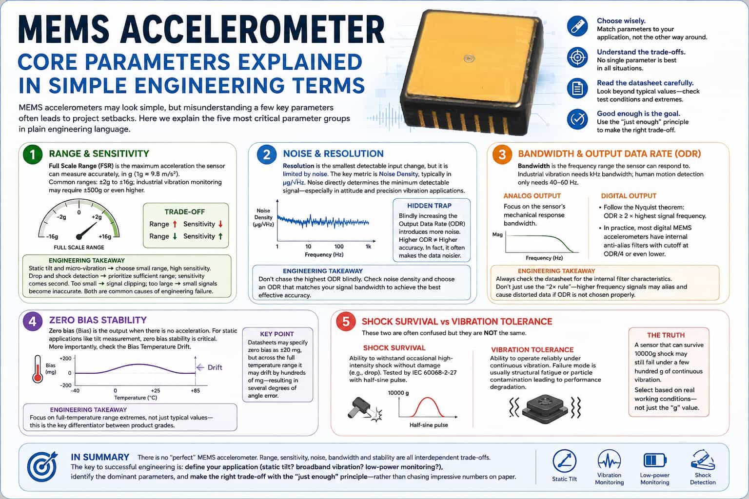
While MEMS accelerometers may appear simple during the engineering selection process, misunderstandings regarding a few core parameters often lead to costly setbacks. The following section explains the five most critical sets of parameters using engineering terminology, avoiding overly abstract theory. **Full-Scale Range and Sensitivity** Full-scale range refers to the maximum acceleration a sensor can accurately measure, typically expressed in *g* (where 1*g* ≈ 9.8 m/s²). Standard applications usually range from ±2*g* to ±16*g*, whereas industrial vibration monitoring may require ±500*g* or higher. Range and sensitivity are generally inversely proportional; a higher range comes at the cost of sensitivity to small signals. The selection logic is straightforward: choose a low range and high sensitivity for static tilt measurement or micro-vibration monitoring; conversely, prioritize sufficient range for drop or shock detection, where sensitivity is a secondary concern. Selecting a range that is too low leads to signal clipping, while one that is too high results in poor accuracy for small signals—both scenarios are common causes of engineering failure. **Noise and Resolution** Resolution represents the smallest input change a sensor can distinguish, yet it is constrained by noise. The key metric here is noise spectral density, typically measured in µg/√Hz. Noise directly determines the minimum detectable signal; in applications such as attitude sensing and precision vibration monitoring, noise levels warrant greater attention than resolution. A common engineering pitfall is the blind increase of the Output Data Rate (ODR), which introduces more noise. Many developers push the ODR to its maximum, only to find the resulting data riddled with noise; the root cause is that higher sampling rates often degrade effective precision. **Bandwidth and Output Data Rate (ODR)** Bandwidth defines the frequency range of input signals to which the sensor can respond. Industrial vibration monitoring requires a bandwidth of several kilohertz, whereas 40–60 Hz suffices for human motion tracking. For analog outputs, the focus is on the sensor's mechanical response bandwidth; for digital outputs, the Nyquist sampling theorem applies—meaning the ODR must be at least twice the highest signal frequency. A more subtle issue in practical engineering is that the internal anti-aliasing filter cutoff frequency for most digital MEMS accelerometers is only one-quarter (or less) of the ODR. If the ODR is selected based solely on the "2x" rule during mechanical design, high-frequency signal aliasing will directly result in data distortion. Always consult the filter characteristics in the datasheet rather than relying on theoretical formulas. Bias Stability Bias refers to the output value when no acceleration is present. For static applications such as tilt detection, bias stability is of paramount importance. Even more critical is bias temperature drift. Some devices may specify a bias of ±20 mg in their datasheets, yet drift by hundreds of milligrams across the full temperature range—an error that translates into a deviation of several degrees in angle. This is a key differentiator between product grades; one must focus on extreme values across the full temperature range rather than typical values. Shock Limit vs. Vibration Tolerance These parameters are easily confused. Shock resistance refers to the ability to withstand occasional, high-intensity impacts (such as drops) without damage; the testing standard is IEC 60068-2-27, utilizing a half-sine pulse. Vibration tolerance, conversely, concerns the ability to operate reliably over the long term under continuous vibration, where failure modes include structural fatigue or performance degradation caused by particulate contamination. The two are not interchangeable; a sensor capable of withstanding a 10,000g shock might fail under continuous vibration of only a few hundred g. Selection must be based on the actual operating environment rather than simply prioritizing the highest "g-rating." In summary, there is no "universal parameter" for selecting MEMS accelerometers; the factors of range, sensitivity, noise, bandwidth, and stability involve inherent trade-offs. Successful engineering implementation relies on clearly defining the application scenario (e.g., static tilt, broadband vibration, or low-power monitoring), identifying the dominant parameters, and making choices based on the principle of "sufficiency" rather than chasing impressive specifications on paper.
Read More
MEMS accelerometers have evolved from early consumer electronics accessories into a diverse family of sensors spanning industrial, automotive, and even navigation-grade applications. In the absence of unified industry-wide standards, they are typically categorized by performance—ranging from low to high—into consumer-grade, industrial/automotive-grade, tactical-grade, and navigation/military-grade. The core differences between these grades lie in key metrics such as noise density, bias stability, and temperature drift; these parameters directly determine their suitability for specific use cases. Consumer-grade accelerometers offer low cost and low power consumption, typically featuring measurement ranges of ±1g to a few g and relatively narrow bandwidths. With poorer bias repeatability (typically around 25mg), they primarily serve motion-sensing applications that do not require high precision, such as smartphone screen rotation, step counting, and game controllers. Industrial and automotive-grade devices offer performance improvements of ten to a hundredfold, with typical bias repeatability reaching 0.25mg and noise density as low as 25μg/√Hz. They cover a wider measurement range—from ±2g for tilt sensing to ±40g for platform stabilization—with some models reaching up to ±500g for vibration monitoring. These devices often utilize hermetic packaging to ensure reliable operation across a wide temperature range of -40°C to +125°C. Typical applications include structural health monitoring (SHM) for bridges and wind turbines, condition-based monitoring (CBM) for factory equipment, inclinometers, and electronic stability control (ESC) systems. Sensors of this grade are essential for applications requiring tilt accuracy better than 1°. The latest industrial-grade products may also incorporate an embedded machine learning core (MLC) to process inference algorithms directly at the sensor level, enabling local decision-making. Tactical and navigation-grade sensors prioritize ultimate performance for use in aircraft navigation, weapon guidance, and submarine inertial navigation systems; they feature bandwidths exceeding 300Hz and must meet extremely rigorous requirements for long-term stability and resistance to vibration rectification effects. Additionally, specialized high-g accelerometers with ranges reaching 320g or even 1000g have emerged for extreme shock scenarios, such as airbag deployment and spacecraft collision detection. Ultimately, selecting an accelerometer involves balancing cost against precision: consumer-grade sensors address basic functionality ("presence vs. absence"), industrial-grade sensors assess quality ("good vs. bad"), and navigation-grade sensors determine mission success or failure ("life vs. death"). Understanding the application's actual requirements regarding precision, temperature range, reliability, and level of intelligence is key to selecting the right model.
Read More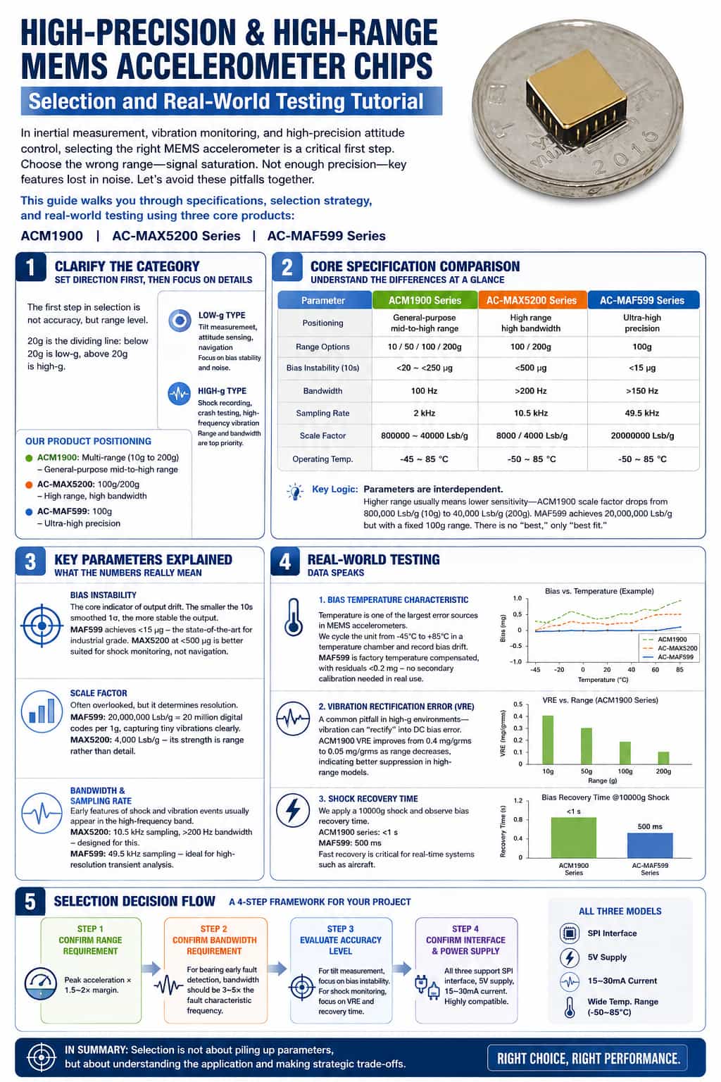
Introduction: In applications such as inertial measurement, vibration monitoring, and high-precision attitude control, selecting the right MEMS accelerometer is often the critical step that determines a system's success or failure. Choosing a range that is too low leads to signal saturation and clipping; insufficient precision causes key features to be drowned out by noise—these are pitfalls many engineers have encountered. Today, using three core products—the ACM1900, AC-MAX5200 series, and AC-MAF599 series—we will guide you through understanding key datasheet specifications and walk you through the entire process from selection to actual testing. This is more than just a lesson on component selection; it is a reusable technical methodology. Part 1: Clarifying Classifications—Set the Direction Before Drilling into Details The first step in selection isn't looking at precision, but at the measurement range class. MEMS accelerometers are typically categorized with 20g as the threshold: ranges below this are "low-g," while those above are "high-g." Low-g types: Used for tilt detection, attitude sensing, and navigation—where bias stability and noise performance are the critical tests. High-g types: Used for shock recording, crash testing, and high-frequency vibration monitoring—where range and bandwidth are the top priorities. Relating this to the three series we are discussing today: · ACM1900: Covers multiple ranges from 10g to 200g; a general-purpose model for medium-to-high ranges. · AC-MAX5200: 100g/200g ranges; high range and high bandwidth, suitable for shock and vibration monitoring. · AC-MAF599: 100g range; ultra-high precision, suitable for inertial navigation and attitude control. Clarifying this positioning ensures the subsequent selection process stays on the right track. Part 2: Comparing Core Specifications—Understanding Differences at a Glance Next, we move to the core technical details: a comparison of the specifications for these three product series. Specifications ACM1900 Series AC-MAX5200 Series AC-MAF599 Orientation General-purpose, medium-to-high range High Range, High Bandwidth Ultra-high precision type Range Options 10/50/100/200 g 100/200g 100 g Bias Stability (10s) <20 to <250 µg <500 µg <15 µg Bandwidth 100 Hz >200 Hz >150 Hz Sampling Rate 2 kHz 10.5 kHz 49.5 kHz Scale Factor 800,000 to 40,000 LSB/g 8000/4000 LSB/g 20,000,000 LSB/g Operating Temperature -45 to 85°C -50 to 85°C -50 to 85°C This chart reveals a fundamental principle: parameters involve trade-offs. A wide measurement range often implies reduced sensitivity—for the ACM1900, as the range increases from 10g to 200g, the scale factor drops from 800,000 to 40,000; conversely, the ultra-high-precision MAF599 boasts a scale factor of 20 million but has a fixed range of 100g. There is no single "best" choice—only the one that best fits the application. Part 3: Key Parameter Analysis—What Do These Numbers Mean? Bias Stability This is a core metric for measuring accelerometer output drift. A lower 1σ value (based on 10-second smoothing) indicates greater output stability. The MAF599 achieves <15 µg, representing the pinnacle of industrial-grade performance. In contrast, the MAX5200 offers <500 µg, making it better suited for shock monitoring than for navigation-grade applications. Scale Factor Often overlooked during selection, this parameter determines resolution. The MAF599’s scale factor of 20 million LSB/g means that 1g of acceleration corresponds to 20 million digital codes, allowing for the clear capture of minute vibrations. The MAX5200, with 4,000 LSB/g, prioritizes a wide measurement range over fine detail resolution. Bandwidth and Sampling Rate Early-stage characteristics of shock and vibration events often manifest in high-frequency ranges. The MAX5200 is specifically designed for this, featuring a 10.5 kHz sampling rate and a bandwidth exceeding 200 Hz. Meanwhile, the MAF599’s 49.5 kHz sampling rate is ideal for transient analysis requiring high temporal resolution. Part 4: Empirical Validation—Letting the Data Speak Once a model is selected, actual testing provides the ultimate verification. We focus on three key dimensions: First, bias temperature characteristics. Temperature is a primary source of error for MEMS accelerometers. During testing, we cycled the devices in a temperature chamber from -45°C to 85°C to record bias drift. The MAF599 undergoes factory temperature compensation, keeping residual error below 0.2 mg; in practical terms, this eliminates the need for secondary calibration. Second, vibration rectification error. This is a common pitfall in high-g environments: vibration itself can be "rectified" into a DC bias error. The ACM1900’s VRE (Vibration Rectification Error) decreases from 0.4 mg/grms to 0.05 mg/grms as the full-scale range increases, indicating that higher-range models offer superior rejection of strong vibrations. Third, consider shock recovery time. Measurements taken after applying a 10,000g shock show the time required for the bias to recover. The recovery time is less than 1 second for the entire ACM1900 series and 500 ms for the MAF599—a critical factor for real-time systems such as those used in aircraft. Part 5: Selection Decision Flowchart Finally, I present a four-step selection decision process that can serve as a reference framework for your project's component selection.
Read More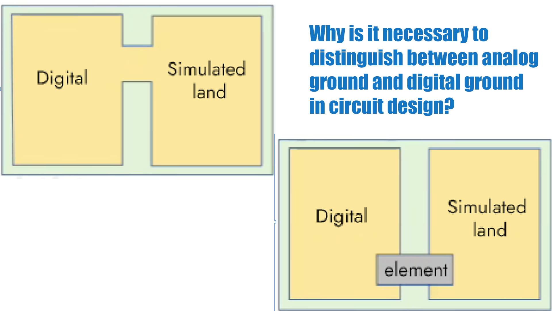
The sensor unit circuits we typically design include both digital signal processing circuits (such as an MCU) and analog circuits (including the front-end sensor and its signal amplification). Simply put, digital ground is the common reference terminal for the digital circuitry, i.e., the reference terminal for digital voltage signals; analog ground is the common reference terminal for the analog circuitry, the voltage reference terminal (zero potential point) for analog signals. Since digital signals are generally rectangular waves with a large number of harmonics, if the digital ground and analog ground on the circuit board are not separated at the connection point, the harmonics in the digital signal can easily interfere with the waveform of the analog signal. When the analog signal is a high-frequency or high-voltage signal, it will also affect the normal operation of the digital circuit. Analog circuits deal with weak signals, but digital circuits have higher threshold levels, so their power supply requirements are lower than those of analog circuits. In systems with both digital and analog circuits, noise generated by the digital circuits can affect the analog circuits, degrading their small-signal performance. To ensure signal integrity and avoid mutual interference, the analog ground and digital ground must be separated. In schematic design, the ground plane of the digital area is labeled DGND, and the ground plane of the analog area is labeled AGND. Then, in PCB design, the ground plane is divided into digital ground and analog ground, with a large distance between them. The digital ground and analog ground should be grounded at a single point, either directly or through component isolation. 1. Direct Connection. As shown in Figure 1, the two are connected at a single point through a wide copper foil. This method is suitable for low-frequency systems or systems that are not sensitive to noise. 2. Component Isolation Connection. As shown in Figure 2, this connection method uses a ferrite bead or a 0-ohm resistor to connect the components. This is a primary connection method. The equivalent circuit of a ferrite bead is similar to a band-stop notch filter, suppressing noise only at a specific frequency. If the frequency range of the noise is known, a ferrite bead is the best choice. A 0-ohm resistor acts as a very narrow current path, effectively limiting the loop current and suppressing noise. Resistors have attenuation effects across all frequency bands (even a 0-ohm resistor has impedance), making a 0-ohm resistor the best choice when the noise frequency range is uncertain.
Read More
Compared with traditional accelerometers, quartz flexible accelerometers have higher accuracy and reliability. Its high precision can be reflected in the accuracy of data, while its reliability can be reflected in the stability and lifespan of equipment operation. In addition, due to the insensitivity of quartz crystals to temperature and time changes, quartz accelerometers are also more capable of ensuring long-term and stable operation than other accelerometers. Quartz flexible accelerometers have become core sensors in aerospace, defense, industrial monitoring, and other fields due to their ultra-high precision, strong impact resistance, and extreme environmental adaptability. Aerospace and Space Exploration In spacecraft docking missions, quartz accelerometers are used to detect μg (microgravity) level acceleration, providing real-time velocity increment and attitude adjustment data to ensure docking accuracy. When the spacecraft returns to the atmosphere, it needs to withstand a high overload of 3-5g while maintaining measurement stability. When used for satellite attitude adjustment and rocket launch monitoring tasks, quartz flexible accelerometers can achieve an accuracy of 60 μg with zero bias repeatability and withstand 1000g instantaneous impact (such as rocket separation). Meanwhile, the quartz flexible accelerometer can provide gravity field data for the lander, supporting precise soft landing. In space microgravity experiments, quartz flexible accelerometers are used to measure the six degree of freedom motion of loads, with an accuracy of "observing hair falling to the ground" level to eliminate vibration interference. National Defense and Military Equipment The inertial navigation system of long-range ballistic missiles and tactical missiles relies on quartz accelerometers to maintain scale factor stability (<30ppm) in impact environments of 500-1000g, ensuring ballistic accuracy. For example, it needs to withstand 100g/5ms half sine wave impact, which is suitable for high overload at the moment of missile launch. In the application of armored vehicles and drones, the stability control of tanks and armored vehicles needs to continuously output reliable data in a vibration environment (20-2000Hz random vibration). The drone navigation system utilizes the low-power (<480mW) and lightweight (<65g) characteristics of quartz flexible accelerometers to extend range and enhance maneuverability. Industrial and Infrastructure Safety Monitoring Quartz accelerometers are applied in monitoring landslides and debris flows, capturing surface micro deformations with a resolution of μg to achieve early geological hazard warning. In deformation monitoring of bridges and high-speed railways, quartz flexible accelerometers can provide long-term stability (monthly drift<50 μg) and reduce maintenance costs. In the field of energy exploration, oil drilling measurement systems (such as wireless inclinometers) rely on their high temperature resistance (185℃) to provide inclination data in high-pressure impact environments underground. Unique Advantages Support High Demand Scenarios The core advantages of quartz flexible accelerometers lie in their ultra-high accuracy and long-term stability, with scale factor drift reaching ppm level and zero bias stability reaching μg/√h level. Taking the AC-3 series quartz flexible accelerometer produced by Micro-Magic Inc as an example: Parameters AC-3A AC-3B AC-3C Unit Threshold /Resolution 5 5 5 μg Bias drift (1σ, one month) ≤15 ≤50 ≤50 μg Repeatability of scale factor (1σ, one month) ≤15 ≤50 ≤50 ppm Bias thermal coefficient ≤ ±15 ≤ ±50 ≤ ±50 μg/℃ Scale factor thermal coefficient ≤ ±15 ≤ ±80 ≤ ±50 ppm/℃ Quartz flexible accelerometers have excellent impact resistance. Its high hardness fused silica integrated structure and frictionless flexible design enable it to withstand 1000g/0.5ms half sine impact, which is far superior to ordinary MEMS sensors. Taking the AC-4 series products produced by Micro-Magic Inc as an example: Parameters AC-4A AC-4B AC-4C Unit Shock 500g 1000g 1000g 0.5ms, 1/2sin Vibration peak sin (@30~500Hz) 25 25 25 g Quartz flexible accelerometers exhibit excellent environmental adaptability over a wide temperature range, such as . The extremely low thermal expansion coefficient and symmetrical structure of quartz material result in minimal temperature drift (as low as ppm/° C), making it a reliable choice for high-precision measurement in extreme temperature environments such as aerospace and military. Taking the AC-6 series products produced by Micro-Magic Inc as an example: Parameters AC-6A AC-6B Unit Bias thermal coefficient ≤ ±80 ≤ ±150 μg/℃ Scale factor thermal coefficient ≤100 ≤200 ppm/℃ Temperature range (Operating) -40 ~ +150 -40 ~ +150 ℃ Temperature range (Saved) -60 ~ +180 -60 ~ +180 ℃ Conclusion With its excellent precision, outstanding long-term stability, and outstanding resistance to extreme environments, quartz flexible accelerometers have firmly established their position as the core device for precise monitoring in the aerospace and military industry. It plays an irreplaceable key role in high-precision inertial navigation, aircraft attitude control, and various precision measurement tasks.
Read More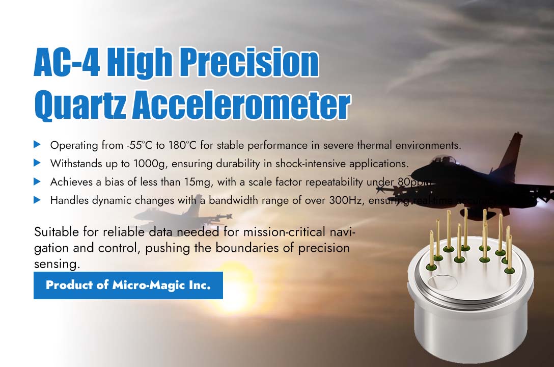
Micro-Magic Inc recently announced that its customized AC-4 series quartz flexible accelerometer has been successfully applied to the navigation and control system of a certain type of high-speed flying vehicle, solving the problem of precise inertial measurement in severe aerodynamic heating and complex vibration environments. When flying at high speeds, the surface of the shell of such aircraft will experience sustained high temperatures due to intense aerodynamic friction. At the same time, complex flight attitudes and engine operation will also introduce strong vibrations and impacts. Under such "thermal-vibration composite" extreme environments, ordinary inertial sensors are prone to performance degradation or even failure, leading to "loss of lock" of navigation signals. This is one of the key technical bottlenecks in the development of the entire system. The design of the AC-4 series accelerometer is precisely aimed at addressing this challenge. The product adopts a unique high-temperature design and dual-torque structure, ensuring performance stability within the harsh temperature range of -55°C to 180°C. Its high mechanical shock resistance of up to 1000g and excellent vibration rectification error (<30μg/g²) indicators mean that it can accurately separate and measure useful acceleration signals in intense dynamic environments, rather than being overwhelmed by environmental noise. "For high-speed aircraft, the 'brain' of the control system relies on the most 'clean' and reliable attitude and acceleration data," explained the product manager of Micro-Magic. "The AC-4's bias value as low as less than 15mg and its scale factor monthly repeatability of less than 80 ppm provide a stable and reliable input benchmark for flight control. And its bandwidth exceeding 300Hz enables rapid response to dynamic changes in the aircraft, ensuring real-time and precise control. This is the key to achieving stable flight and precise guidance." The feedback from the customer confirms the performance of AC-4: "In our comprehensive environmental reliability test, AC-4 underwent a complete temperature-vibration-shock three-dimensional test profile. The results demonstrate that under extreme conditions of simultaneous high temperature and high-frequency vibration, its bias temperature coefficient (<50μg/℃) and scale factor temperature drift (<100ppm) are effectively controlled, and the output signal remains highly consistent and reliable. It successfully plays the role of a reliable 'sensory neuron' in the 'nervous system' of our next-generation aircraft." The General Manager of Micro-Magic stated, "Since its launch, the AC-4 platform has demonstrated unparalleled long-term reliability in the field of petroleum drilling. Today, we are introducing this time-tested and mature product to the cutting-edge aerospace sector, where equally stringent reliability standards are required. This is not merely a shift in application scenarios but a natural extension of our core technological strengths. We are honored to provide a solid force from the basic sensing field to promote the development of hypersonic technology."
Read More
In the fields of inertial navigation, aerospace, and precision industrial measurement, high-precision and highly synchronized acquisition of physical signals is the core to ensuring system performance. The 32-bit high-precision A/D conversion circuit specifically designed for accelerometers, introduced by Micro-Magic Inc, is a key component tailored for such high-end applications. With its exceptional performance and flexible architecture, it provides a solid foundation for building reliable high-precision inertial navigation signal acquisition systems. The core advantage of this A/D board lies in its exceptionally high measurement accuracy and stability. Supporting a current input range of ±50mA, combined with 32-bit A/D conversion capability, it can precisely capture minute current variations output by accelerometers. Within the full operating temperature range (-40°C to +70°C), its zero temperature coefficient is better than ±2nA/°C, and the scale factor temperature coefficient is below 3.0 ppm/°C. This means the system can maintain extremely low measurement drift even under complex ambient temperature fluctuations, ensuring long-term accuracy in navigation solutions. Additionally, the product boasts ultra-high stability, with zero stability and scale factor stability reaching the nA and ppm levels respectively, guaranteeing repeatable and reliable data output while effectively reducing the system's noise floor. Inertial navigation systems require extremely strict synchronization of multi axis data. This A/D board provides a precise synchronization solution to ensure data spatiotemporal consistency: Internal/external synchronization mode: it can be flexibly switched according to system instructions. In internal synchronization mode, the board autonomously generates a sampling clock; In external synchronization mode, RS422 differential synchronization signals are received from the navigation computer to achieve a unified sampling time for the entire system, perfectly eliminating timing errors between channels. ⚪ Latching and triggering: Latching the A/D values of all channels at the falling edge of the synchronization signal ensures that the acceleration and temperature data of the X, Y, and Z axes are captured at the same moment, providing a spatiotemporal consistent data source for subsequent navigation algorithms. Inertial navigation systems require extremely strict synchronization of multi axis data. This A/D board provides a precise synchronization solution to ensure data spatiotemporal consistency: ⚪ Internal/external synchronization mode: it can be flexibly switched according to system instructions. In internal synchronization mode, the board autonomously generates a sampling clock; In external synchronization mode, RS422 differential synchronization signals are received from the navigation computer to achieve a unified sampling time for the entire system, perfectly eliminating timing errors between channels. ⚪ Latching and triggering: Latching the A/D values of all channels at the falling edge of the synchronization signal ensures that the acceleration and temperature data of the X, Y, and Z axes are captured at the same moment, providing a spatiotemporal consistent data source for subsequent navigation algorithms.
Read More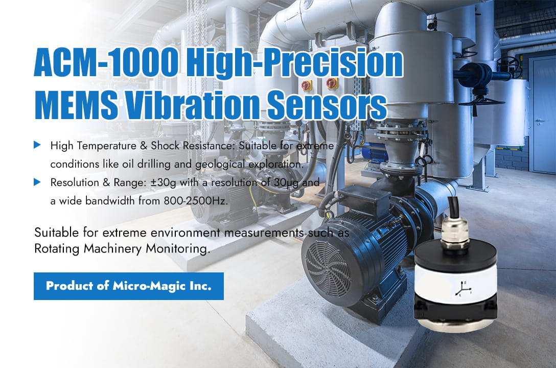
Vibration detection of industrial equipment has become a core component of predictive maintenance. The changes in vibration signals can reflect potential faults such as bearing wear, abnormal gear meshing, and rotor imbalance. MEMS (Micro Electro Mechanical Systems) sensors, with their advantages of miniaturization, high sensitivity, and low cost, are gradually replacing traditional piezoelectric sensors and becoming the mainstream technology for vibration detection. The following introduces the main applications and technical characteristics of MEMS sensors in industrial equipment vibration detection. 1. Main Application Scenarios (1) Monitoring of rotating machinery in industrial equipment For industrial equipment such as motors, pumps, fans, compressors, gearboxes, generators,and turbines, MEMS vibration sensors can detect vibrations caused by uneven mass distribution in rotating components, as well as vibrations resulting from misaligned shaft centerlines at couplings (including parallel misalignment and angular misalignment). For bearing faults, MEMS vibration sensors detect incipient damage in rolling or sliding bearings (such as pitting, spalling, cracks, and wear). (2) Condition monitoring and predictive maintenance MEMS vibration sensors have small size and low power consumption, making them ideal for installation on critical equipment for continuous vibration data acquisition and achieving online status monitoring. By analyzing the trend changes, spectral characteristics (such as fault characteristic frequencies), envelope analysis, etc. of vibration signals, early warning of equipment failures can be provided. (3) Shock and transient event detection MEMS accelerometers have wideband response (DC response) characteristics and can detect events such as impact, collision, and transient vibration caused by valve opening and closing, which may cause damage to the equipment or indicate potential problems. 2. Technical Advantages of MEMS sensors (compared to traditional piezoelectric vibration sensors) The ultra-low cost of MEMS sensors is the most critical factor driving their large-scale deployment. The price is much lower than traditional industrial grade vibration sensors, making it economically feasible to deploy a large number of sensors on a single device or multiple measurement points. The extremely low power consumption of MEMS sensors makes them highly suitable for battery powered wireless sensor network applications, enabling long-term maintenance free operation. MEMS sensors are small in size and light in weight, with almost no load effect (mass effect) on the measured object. They are flexible in installation methods such as bonding and magnetic attraction, making them particularly suitable for small devices or space limited scenarios. 3. Potential Challenges and Critical Precautions The high-frequency response limitation of MEMS sensors is the main limitation of MEMS sensors in the field of vibration detection. Traditional piezoelectric sensors easily cover the 10kHz or even higher frequency range (such as 40kHz), while industrial grade MEMS sensors typically achieve a flat response in the 3kHz-10kHz range. This weakens the ability to detect early failures of ultra high speed bearings (whose fault characteristic frequency may be high) or high-frequency components of gear meshing, and requires careful selection of sensor models based on the characteristic frequency range of the tested equipment. In addition, standard consumer or industrial grade MEMS sensors typically operate at temperatures ranging from -40 ° C to+85 ° C or+105 ° C. For certain industrial environments (such as near engines, turbines), specialized high-temperature MEMS (up to+125 ° C or even higher) or insulation measures may be required. Piezoelectric sensors typically have a wider temperature selection range. 4. MEMS Vibration Sensor Products The MEMS vibration sensor ACM-1000 produced by Micro-Magic Inc is designed according to industrial standards and uses digital filtering technology to effectively reduce measurement noise and improve measurement accuracy. Suitable for multiple fields such as vibration testing, impact testing, shock testing, etc. The ACM-1000 can directly output the three-axis vibration velocity, angle, amplitude (displacement), frequency, and temperature of an object, and determine whether the measured object (bridge, fan, rotating machinery bearing vibration measurement and real-time monitoring) is damaged, making it convenient for users to analyze data. For example, machine failures caused by shaft system failures (blade wear, dynamic imbalance, poor alignment), bearing failures (bearing damage, poor lubrication, bearing collision, bearing looseness), transmission failures (gear wear, belt wear, coupling wear, gear pitting and peeling), etc., can be detected in advance by vibration sensors to issue alarms, preventing the machine from continuing to work under adverse conditions and causing damage. ACM-1000 Performance Indicators Parameter Item ACM-1000 Measuring axis X、Y、Z(optional) Accuracy Vibration velocity 1mm/s Vibration angle 0.001°/s Vibration amplitude 0.001mm Vibration frequency 1Hz Temperature Compensation -40 ~ +85℃ Range Vibration velocity(0-50mm/s),Vibration angle(0 ~ 180°) Vibration amplitude(displacement 30mm),Vibration frequency(1~100Hz) Bandwidth(3DB) 500HZ In addition, Micro-Magic Inc has also launched the ACM-100, ACM-200, and ACM-300 series high-precision accelerometer products according to different application scenarios, suitable for multiple industrial fields such as vibration testing, impact testing, fatigue monitoring, and prediction. Facilitate customers to flexibly configure according to different application scenarios. Conclusion MEMS sensors are revolutionizing the field of industrial equipment vibration detection due to their disruptive cost advantages, low power consumption, small size, and ease of digital integration. It greatly reduces the threshold for condition monitoring and predictive maintenance, making continuous monitoring possible on a wider range of devices and more measurement points, especially in vibration analysis in the mid to low frequency range (such as unbalance, misalignment, early bearing failure, looseness, etc.) and the construction of large-scale wireless monitoring networks. ACM-100 ACM-300 ACM-1000
Read More
Quartz flexible accelerometers are widely used in aerospace, inertial navigation, precision measurement and other fields due to their advantages of high precision and stability. However, its core sensitive component - quartz flexible pendulum - is very fragile and extremely sensitive to vibration environments. Vibration may cause performance degradation, zero shift, and even structural damage. Therefore, strict vibration testing and effective anti vibration measures are crucial. Purpose of Vibration Testing The purpose of vibration testing is to evaluate the performance, structural integrity, and reliability of accelerometers in actual or expected vibration environments. The main types of testing include sine vibration testing and random vibration testing. Sine vibration testing is to find the resonant frequency of the structure and evaluate its response and tolerance at specific frequencies. Typically, within the specified frequency range (e.g., 5 Hz – 2000 Hz or higher, according to the specification), a linear or logarithmic sweep is performed along three mutually perpendicular axes. Frequencies exhibiting an abnormal increase in accelerometer output (response amplification) are recorded. Special attention should be paid to the first-order and second-order flexural resonant frequencies of the quartz flexure, as these frequencies are most prone to damage. The relationship between the input vibration and output signal is analyzed. Perform fixed frequency vibration for a specified duration (such as several minutes) on the identified resonant frequency points (especially the pendulum resonance points) to test their fatigue life and stability. Random vibration testing is to simulate wideband, random vibration excitations in actual environments (such as rocket launches, engine noise, aerodynamic turbulence, vehicle driving), and evaluate their comprehensive performance under statistically distributed vibrations. Apply vibrations with specific power spectral density patterns along three mutually perpendicular axes within the specified frequency range. The scale of testing is usually higher than that of sine testing, which can better reflect the real environment. PSD spectra and Grms values are developed based on specifications or measured data. The key monitoring parameters in the test include output signals, physical status, and performance verification. The output signal mainly observes zero offset, scale factor changes, increased noise levels, abnormal outputs (saturation, oscillation), etc; The physical state mainly involves checking whether the accelerometer has any abnormal noise, whether the structure is loose, and whether there is any damage to the appearance (after testing, the cover needs to be opened to check the swing plate); Performance validation mainly involves comprehensive static performance testing of accelerometers before, during, and after vibration (zero bias, scale factor, second-order nonlinearity, threshold, resolution, repeatability, etc.), comparing the effects of vibration. Vibration Mitigation Measures To address the vulnerability of quartz flexure accelerometers, vibration resistance measures must be implemented at multiple levels. (1) Core sensitive structure design and process Firstly, it is necessary to optimize the design of the oscillating plate. While meeting the requirements of sensitivity and bandwidth, the thickness of the oscillating plate should be appropriately increased (balancing sensitivity), the shape and support structure should be optimized, and the lowest order resonant frequency should be maximized to be higher than the expected main vibration environment frequency (ideally higher than twice). Avoid resonance frequencies falling in the main vibration energy concentration zone. Secondly, it is precision manufacturing and assembly, strictly controlling the machining accuracy and symmetry of key components such as swing plates, torque converter coils, differential capacitor plates, etc., to ensure uniform stress distribution and reduce internal stress concentration points. Reliable processes such as laser welding are used to connect the swing plates to the base. Finally, the selection of materials should be based on high-strength and high stability quartz materials, and the stiffness and damping characteristics of the base and shell materials should also be considered. (2) Internal mechanical isolation and damping Firstly, apply a small amount of special damping adhesive (such as silicone rubber base) on the non sensitive area of the swing plate or the supporting beam. This is one of the most commonly used and effective measures, which can significantly reduce the resonance Q value and decrease the resonance amplification factor. However, extreme caution should be taken to avoid affecting sensor performance (such as introducing thermal stress, affecting symmetry, and increasing mass). Secondly, a micro isolation system (such as low stiffness, high damping rubber pads, metal rubber, micro wire rope isolators, etc.) should be designed between the core of accelerometer (including the core components of the swing plate assembly) and the housing base to isolate the transmission of high-frequency vibrations to the sensitive core. The stiffness, damping, and load-bearing capacity need to be carefully designed. (3) Sealing and Filling Encapsulating silicon gel or silicone rubber with low modulus and high damping in the inner cavity of the accelerometer (usually between the core and the shell) is another very effective anti vibration measure (especially anti shock and high-frequency vibration). Silicon gel or silicone rubber provides damping and absorbs vibration energy; Support internal structure and suppress relative motion; Protect internal components from contamination and moisture. The sealing adhesive needs to have extremely low shrinkage stress, excellent thermal stability, good adhesion, low air release, and low permeability (especially for space applications). The sealing process (excluding bubbles and curing) is crucial, as poor sealing can actually introduce stress or contamination. (4) External installation and system level vibration isolation Optimize the installation interface to ensure that the installation base is flat and rigid. Tighten the connecting bolts evenly to the specified torque to avoid introducing local stress or reducing overall stiffness due to improper installation. At the same time, install appropriate external shock absorbers between the accelerometer and vibration sources such as engine mounts and aircraft structures. Select the type of isolator (such as metal rubber isolator, wire rope isolator, viscoelastic damping isolator) based on the characteristics of the main vibration frequency, and its natural frequency should be much lower (usually <1/√ 2 times) than the lowest main vibration frequency that needs to be isolated. The load-bearing capacity of the isolator, environmental adaptability (temperature, vacuum), and the impact on the low-frequency performance of the sensor also need to be considered. Test cases Taking the AC-9 series high-precision quartz accelerometer produced by Micro-Magic Inc as an example, the influence of vibration environment on the K0 index of the accelerometer is tested. Before vibration, the quartz accelerometer is in a 0g state, the product is powered on, data is collected for 1 minute, and take the average of the data, denoted as ; Start the vibration table under the following vibration conditions: 6g, random vibration at 200~2000Hz, wait for the vibration table to stabilize, collect data for 1 minute, and take the average of the data, denoted as ; Rotating vibration fixture, quartz accelerometer in 0g state, then power on the product, collect data for 1 minute, and take the average of the data, denoted as . By calculation, it can be concluded that: Conclusion The vibration problem of quartz flexible accelerometers is a system engineering issue that needs to be addressed throughout the entire process of design, manufacturing, testing, and application. When selecting and designing anti vibration measures, careful trade-offs must be made to ensure that the core performance indicators of the accelerometer are not significantly sacrificed while improving the anti vibration capability, and other environmental adaptability requirements are met. AC-9
Read More
In the field of precision measurement and control, high-precision current/frequency conversion technology is crucial. The AVI-F series I/F conversion module launched by Micro-Magic Inc has become an ideal choice for high-performance inertial navigation system accelerometer data acquisition, weak current signal digital acquisition and other high demand scenarios due to its excellent performance and stable performance. AVI-F is composed of voltage reference, constant current source, integrator, integrator arm, logic control CPLD, etc. The current signal of the accelerometer can be directly converted into pulse frequency, which is an analog/digital converter with high accuracy and good resolution. AVI-F adopts the principle of charge balance integration, which has the characteristics of signal acquisition without loss, and is less affected by noise such as power supply. It is an ideal circuit for building high-performance inertial navigation systems. What are the core advantages of AVI-F series products? 1. High precision and stability The AVI-F series module adopts a charge integration method, with a maximum output frequency of 256kHz, Zero offset as low as 10nA, and a comprehensive nonlinear error of only 20ppm, ensuring high accuracy and reliability of signal conversion. Its scale factor temperature coefficient is as low as 1ppm/℃, and it exhibits stability throughout the entire temperature range, suitable for harsh environments ranging from -45℃ to 70℃. 2. High standard hardware design High performance components are used, mostly surface-mount devices (SMD), with small size and high precision. The board level uses precision constant current sources and high-precision multimeters for precision calibration, including symmetry and linearity. 3. Multi-functional output interface The module supports three independent pulse outputs (X/Y/Z channels), each containing positive and negative current pulse signals. At the same time, an RS422 serial port function is added, which sends pulse accumulation at a frequency of 1KHz to simplify the data acquisition process and improve system integration efficiency. 4. Low power consumption and localized design The power requirements are ±15V and +5V, with a steady-state current as low as 0.2A and excellent power consumption performance. All components are 100% domestically produced to ensure supply chain security and meet independent and controllable needs. Typical Applications of AVI-F Series Product a. Inertial navigation system: Accurately convert accelerometer signals to improve navigation accuracy. b. Industrial automation: Real time monitoring of current signals and optimization of control processes. c. Research instruments: high-resolution data acquisition to assist in precision experiments. Why choose AVI-F module? The AVI-F series I/F conversion module integrates high precision, low power consumption and multifunctionality, making it a wise choice for users who pursue performance and reliability. Whether in harsh environments or complex applications, it can provide stable and efficient solutions. AVI-F Whatever you needs, Micro-Magic is at your side.
Read More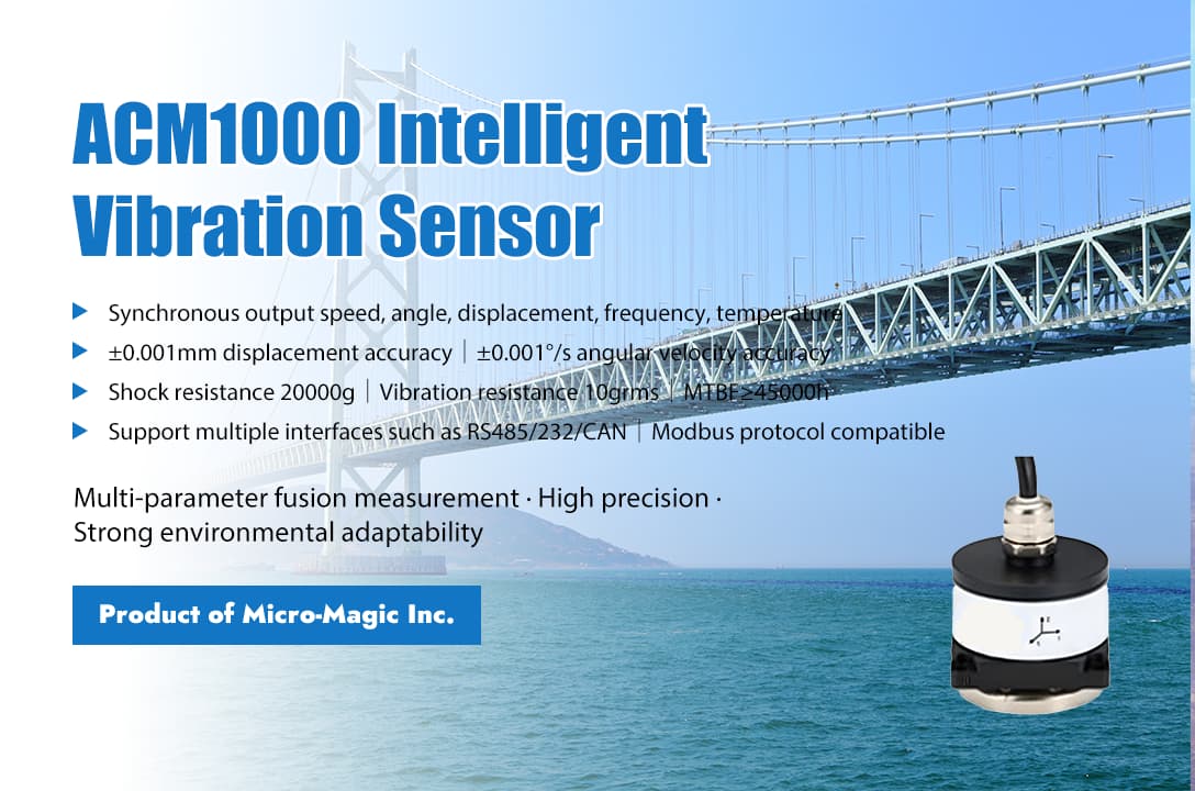
Quickly get the product information in one minute In the field of industrial automation and intelligent monitoring, accurate data collection and reliable equipment status analysis are key to ensuring production safety and efficiency. The ACM1000 digital MEMS vibration sensor launched by Micro-Magic Inc has become an ideal choice in the field of vibration monitoring due to its high precision, multi parameter output, and strong environmental adaptability. ACM1000 adopts a low-noise, low drift, and low-power three-axis MEMS sensor with high-frequency and low-noise characteristics, which is particularly suitable for high-resolution vibration measurement applications. It can detect machine faults as early as possible in equipment status monitoring applications. The product not only has excellent performance, but also has extremely low power consumption. In addition, this sensor can provide accurate and reliable tilt measurement in high impact and high vibration environments without causing sensor saturation. The highlights of the ACM1000 product include the following aspects: 1. Multi parameter integrated measurement The ACM1000 can simultaneously output vibration velocity (0-50mm/s), vibration angle (0-180°), amplitude (displacement 0-30mm), vibration frequency (1-100Hz), and temperature data of three axes (X, Y, Z), fully covering the monitoring requirements of equipment vibration status. 2. High precision and low noise By using digital filtering technology and monocrystalline silicon capacitive sensors, noise interference is effectively reduced, and the measurement accuracy reaches: Vibration speed: ±1mm/s; Vibration angle: ±0.001°/s; Vibration displacement: ± 0.001mm. 3. Industrial grade durable design Wide temperature range (-40℃~+85℃), suitable for extreme environments. Resistant to 20000g of impact and 10grms of vibration, meeting the requirements of harsh industrial scenarios. Mean time between failures≥45000 hours to ensure stable and reliable system operation. 4. Flexible configuration and easy integration Supports multiple interfaces such as RS232/RS485/TTL/RS422/CAN, compatible with Modbus protocol. Address codes (0x01~0xFF) can be set, supporting multi-sensor networking and achieving multi-point monitoring. Built in magnetic base and screw mounting holes for easy deployment. Accurately monitor every vibration, prevent problems before they occur, and help upgrade industrial intelligence. Choose the ACM1000 to equip your equipment with the "Smart Eye"! ACM-1000 Whatever you needs, Micro-Magic is at your side. --
Read More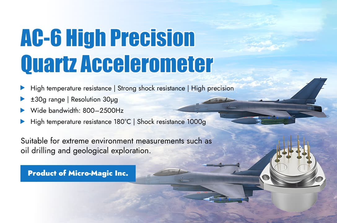
In industries where accuracy, reliability and adaptability to high temperature and vibration-resistant environments are critical, the AC-6 series high-performance quartz flexure accelerometers from Micro-Magic Inc are undoubtedly a disruptive product. Designed specifically for the most challenging high temperature and vibration-resistant environments, this advanced accelerometer is an ideal choice for oil and gas drilling, geophysical exploration and other fields with its unparalleled accuracy and stability. The AC-6 quartz flexible accelerometer product adopts unique miniaturization, high temperature and vibration resistant design, advanced packaging technology and dedicated circuit. Users can select the appropriate sampling resistor through calculation to achieve high-precision output. And according to user requirements, built-in temperature sensors are used to compensate for local values and scaling factors, reducing the impact of environmental temperature. How does AC-6 solve the problems of stability and reliability in high temperature environments? In order to solve the problem of low working life of the accelerometer probe under high temperature, the connection process is improved by using gold wire bonding to connect the terminal post to the gold-plated film on the quartz pendulum. A multi-chip module thick-film hybrid integrated circuit process is adopted for the servo circuit. The substrate used is aluminum oxide ceramic and the conductor is metal gold, which solves the problem of long-term stability under high temperature and has a small error. In the test phase, in order to meet the high-temperature working environment of petroleum logging, the accelerometer underwent high-temperature aging at 180°C for more than 96 hours to ensure long-term stability during high-temperature operation. AC-6 also has the following significant characteristics: Ø Both static and dynamic testing can achieve high-precision measurement, with bias stability (1σ, one month)≤150μg and resolution as low as 30μg. Ø The measurement range reaches ±30g, meeting the acceleration measurement requirements in extreme environments. Bandwidth of 800~2500Hz, suitable for high-frequency dynamic measurement scenarios. Ø The anti-vibration ability reaches 25G (20~2000Hz), and the anti-impact ability is 1000g (0.5ms half sine wave), ensuring stable operation under harsh conditions. The AC-6 quartz accelerometer has become a benchmark product in the field of industrial measurement due to its high precision, high reliability, and excellent adaptability to high temperature and harsh environments. Its mature technology and wide range of applications have validated its outstanding performance. Whether it is static testing in extreme environments or high-frequency dynamic testing, AC-6 can provide users with reliable solutions.
Read Moreleave a message
Scan to Wechat :