




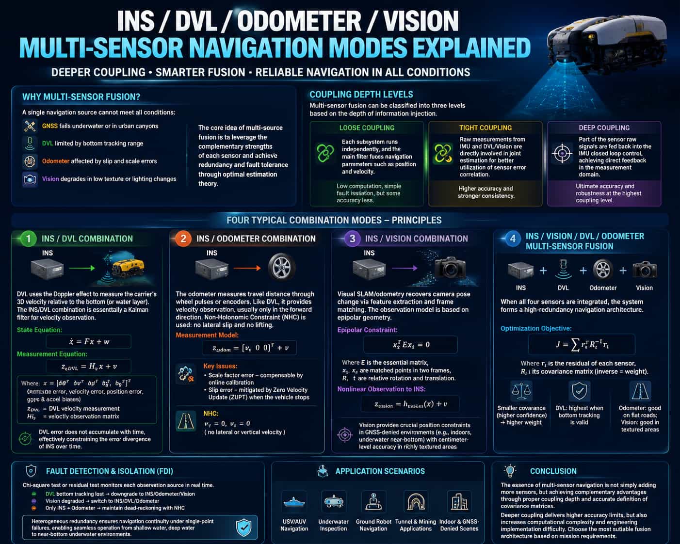
A single navigation source struggles to meet the requirements for full operational coverage: GNSS fails underwater or in urban canyons; DVL is limited by bottom-tracking range; odometry suffers from wheel slip and scale factor errors; and vision-based systems degrade in low-texture environments or under varying lighting conditions. The core concept of multi-source fusion lies in leveraging the complementary characteristics of various sensors to achieve redundancy and fault tolerance through optimal estimation theory. This paper systematically analyzes four typical integrated navigation modes based on two dimensions: coupling depth and information complementarity. **Classification of Coupling Depth** Multi-source fusion can be categorized into three levels based on the depth of information integration: * **Loose coupling** represents the lowest level of coupling, where subsystems perform independent calculations, and a master filter fuses navigation parameters such as position and velocity. Its advantages include low computational load and simple fault isolation; however, accuracy loss arises primarily from the independent nature of the subsystem calculations. * **Tight coupling** elevates observation to the level of raw measurements; raw data from the IMU and DVL (or vision sensors) are directly involved in a joint estimation process, utilizing the temporal correlation of sensor error characteristics to achieve superior estimation. * **Deep coupling** goes a step further by incorporating raw signals from certain sensors into the IMU's closed-loop control, establishing direct feedback in the measurement domain; this represents the highest level of coupling, enabling ultimate precision and maximum robustness. **Principles of Four Integrated Navigation Modes** (1) **INS/DVL Integration** The DVL measures the vehicle's 3D velocity relative to the seabed (or water layer) using the Doppler effect. INS/DVL integration is essentially a Kalman filtering process based on velocity observations: DVL velocity measurements serve as external observations to correct INS velocity errors, thereby suppressing position drift. The state equations and observation equations can be expressed as follows: Here, the state vector $x$ includes attitude, velocity, and position errors, as well as gyro and accelerometer biases, while $H$ is the velocity observation matrix. DVL errors do not accumulate over time, effectively constraining the error growth of the inertial navigation system. INS/Odometer Integration The odometer measures travel distance via wheel pulses or encoders; like the DVL, it falls under the category of velocity observation. However, its constraint is typically limited to forward velocity, necessitating the use of non-holonomic constraints (NHC)—which assume the vehicle neither sideslips nor bounces (i.e., lateral and vertical velocities are zero). Its observation model can be expressed as: Key issues associated with odometry include scale factor errors and wheel-slip errors; the former can be compensated for through online calibration, while the latter requires velocity resetting at standstill intervals using Zero-Velocity Update (ZUPT) techniques. (3) INS/Vision Integration Visual SLAM/odometry recovers changes in camera pose through feature point extraction and inter-frame matching, with an observation model that can be described by epipolar geometry constraints: Here, E = t∧R is the essential matrix, where R and t represent the relative rotation and translation between two frames, forming a nonlinear observation of the inertial navigation system's attitude and position: Vision provides critical positional constraints in GNSS-denied environments (such as indoors or near the seabed), achieving centimeter-level accuracy in texture-rich areas. Tightly coupled visual-inertial systems typically employ sliding-window optimization (e.g., MSCKF) to jointly optimize visual reprojection errors and IMU pre-integration factors, yielding an order-of-magnitude improvement in accuracy compared to loosely coupled systems. (4) Multi-source fusion of INS, vision, DVL, and odometry When all four sensors are integrated, the system establishes a highly redundant navigation architecture. The objective function for optimization is the weighted sum of the residuals from each sensor: The covariance matrix Σ is central to determining fusion weights: the smaller the covariance (indicating lower uncertainty), the higher the weight assigned to the sensor. The DVL carries the highest weight when bottom-tracking is valid; odometry ranks second on smooth terrain; and vision provides lateral constraints in areas rich in visual texture. A Fault Detection and Isolation (FDI) mechanism monitors observation sources in real-time for anomalies using Chi-square or residual tests. If DVL bottom-tracking fails, the system automatically degrades to an INS/odometry/vision fusion mode; if vision degrades, it switches to INS/DVL/odometry; if only INS and odometry remain, it reverts to a pure INS mode constrained by Non-Holonomic Constraints (NHC). A heterogeneous redundant design ensures navigation continuity despite single-point failures, enabling seamless coverage across diverse operational scenarios—from shallow and deep water to near-bottom underwater environments. Conclusion Multi-sensor integrated navigation is not merely about increasing the number of sensors; rather, it relies on the judicious selection of coupling depth and the precise definition of covariance matrices to achieve complementary sensor performance. While deeper coupling offers higher potential accuracy, it also increases computational complexity and engineering implementation challenges; therefore, the optimal fusion architecture should be selected based on specific mission requirements.
Read More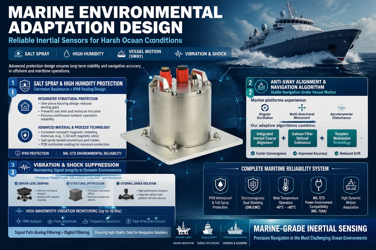
The marine environment poses severe challenges to inertial navigation systems (INS): salt spray corrosion, high humidity condensation, continuous swaying motion, and multi-dimensional vibration all directly affect the system's accuracy and reliability. If the INS cannot effectively cope with these environmental stresses, alignment failures, accuracy degradation, and even hardware damage will occur. Therefore, adaptive design is the core technological barrier that distinguishes marine-grade INS from general-purpose products. Salt Spray and High Humidity Environment Protection Design Chloride ions in salt spray are highly corrosive to metal structural components and electrical connections, while high humidity environments can lead to decreased insulation performance and signal crosstalk. Effective protection strategies should be developed from two aspects: structural sealing and material selection. Integrated structural design reduces assembly gaps and the number of connectors. A one-piece molded shell can fundamentally block the salt spray intrusion path, and combined with positioning grooves and sealing gasket structures, ensures continuous protection during long-term outdoor operations. Regarding material and process selection, the fiber optic ring frame and cover should use magnetic shielding materials (such as 1J50 soft magnetic alloy) to achieve magnetic protection while also ensuring corrosion resistance. Connectors and cables must meet salt spray testing standards, and circuit boards must undergo a three-proof coating process. IP68 protection, conforming to MIL-STD standards, is currently the industry's effective solution for high-humidity salt spray environments. Alignment and Navigation Algorithms under Swaying Conditions Under swaying conditions, the initial alignment of the inertial navigation system (INS) faces two major disturbances: angular sway (periodic attitude changes) and linear vibration (accelerometer output fluctuations). Traditional static base alignment algorithms struggle to converge under these conditions. Anti-sway alignment methods employ an integral inertial frame coarse alignment strategy, utilizing attitude updates to eliminate the influence of angular sway and weakening linear vibration interference through force integration. Based on this, feedback-corrected Kalman filtering is used for fine alignment optimal estimation. Experiments show that this method significantly improves both horizontal and vertical heading accuracy under swaying conditions compared to traditional rotation modulation schemes. Rotation modulation technology is another effective means of suppressing gyro scaling factor errors. By periodically rotating the IMU, constant drift is modulated into a periodically changing signal, which cancels each other out during integration, thereby reducing the long-term impact of swaying on heading accuracy. Vibration Suppression and Shock Resistance Design Vibration affects inertial navigation system (INS) accuracy through two mechanisms: first, mechanical resonance causes IMU output distortion; second, high-frequency vibration couples into the gyroscope and accelerometer measurement channels, forming spurious signals. A three-stage vibration reduction architecture is the current mainstream design approach: the first stage achieves internal damping isolation at the IMU sensor level; the second stage eliminates resonant frequencies through shell structure optimization; and the third stage uses external dampers to physically separate the equipment from the carrier structure. Some high-end systems also integrate high-bandwidth (up to 16kHz) vibration monitoring tools, outputting RMS, peak amplitude, and frequency for each frequency band in real time, providing data support for structural optimization. Analog filtering in the signal pipeline can pre-attenuate vibration noise at the front-end hardware level, and, in conjunction with digital filtering algorithms, ensures the signal quality entering the calculation stage. Comprehensive Protection System In addition to the above-mentioned specialized designs, mature maritime INS systems also need to consider: power environment adaptability (meeting MIL-704A standards), electromagnetic double-layer shielding (to cope with interference from shipboard radar and communication equipment), and wide temperature range operation capability (-40℃~80℃). These measures together constitute a complete design system for adaptability to harsh environments, which is the fundamental guarantee for the inertial navigation system to maintain mapping-level accuracy under marine conditions.
Read More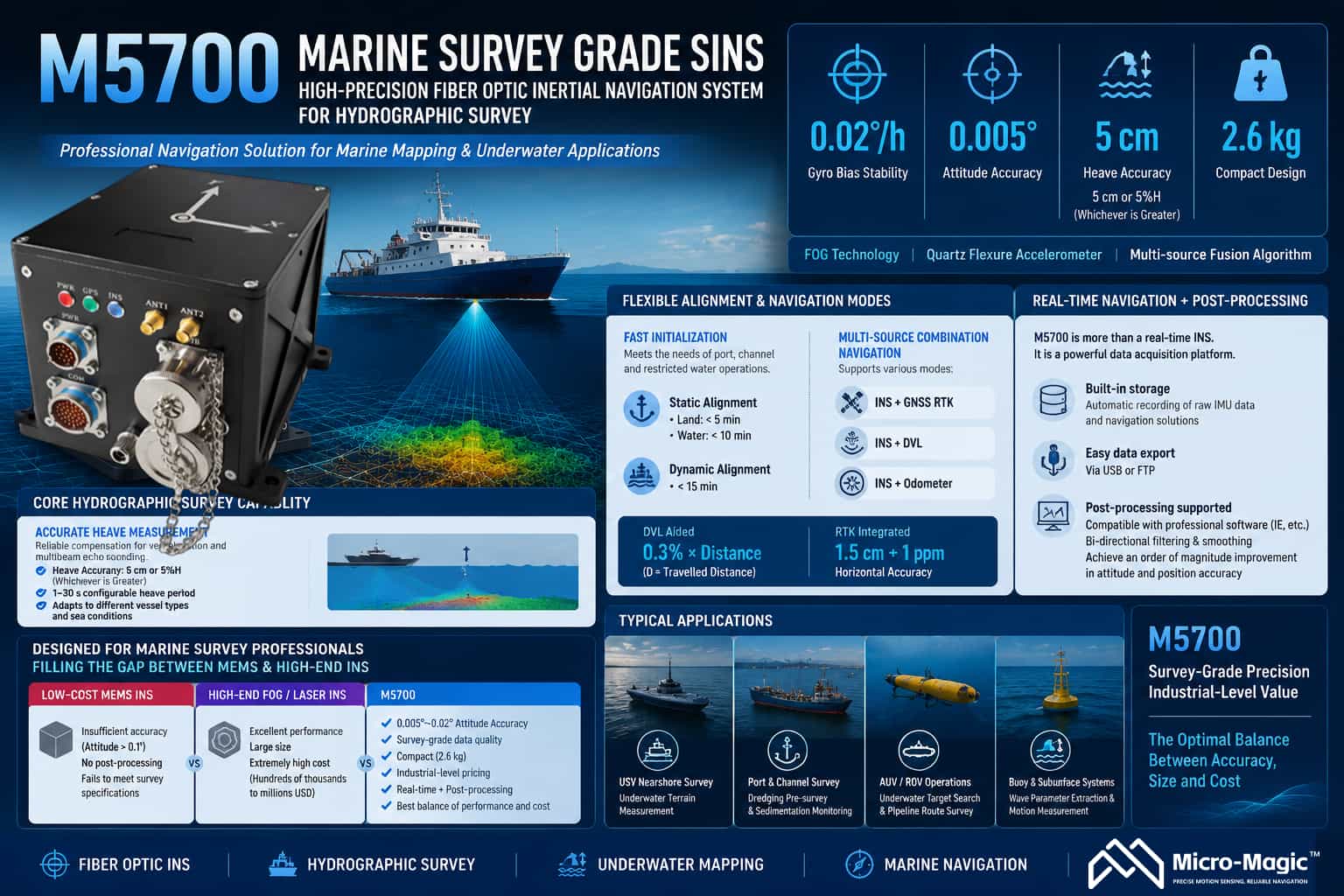
The M5700 Fiber-Optic Inertial Navigation System is a high-precision strapdown inertial navigation system designed for marine surveying and high-end navigation applications. It integrates fiber-optic gyroscopes, quartz flexure accelerometers, and multi-source fusion navigation algorithms. With a gyroscope bias stability of 0.02°/h and an attitude accuracy of 0.005°, the system establishes a strong technical position in the field of maritime surveying. **Core Surveying Capabilities** Heave measurement is a critical requirement in marine surveying. The M5700 offers a heave accuracy of 5 cm or 5% of heave height (whichever is greater), effectively compensating for the impact of vessel motion on multibeam bathymetric data. The system supports configurable heave periods ranging from 1 to 30 seconds, adapting to various sea conditions and vessel characteristics. Alignment solutions are flexibly adapted to operational scenarios: static base alignment takes less than 5 minutes (on land) and less than 10 minutes (in water), while dynamic base alignment takes less than 15 minutes, meeting the need for rapid operations in restricted waters such as ports and channels. Multi-source integrated navigation supports various modes, including Inertial/GNSS, Inertial/DVL, and Inertial/Odometer. With DVL assistance, position accuracy reaches 0.3% of distance traveled (D); when integrated with GNSS RTK, horizontal accuracy reaches 1.5 cm + 1 ppm, ensuring navigation continuity during GNSS signal outages. **Post-processing Capabilities** Post-processing capability is a key differentiator that sets the M5700 apart from purely real-time navigation products. The system features built-in storage, automatically recording raw IMU data and navigation solutions upon power-up, which users can easily export via USB or FTP. The stored IMU data can be directly imported into professional post-processing software (such as IE) for bidirectional filtering and smoothing, yielding attitude and position accuracy an order of magnitude better than real-time solutions. This capability allows the M5700 to serve not only real-time operations but also as a data acquisition front-end, providing the raw data foundation for refined processing and meeting the rigorous accuracy requirements of applications such as hydrographic surveying and underwater terrain modeling. Market Positioning The M5700 is precisely positioned for the mid-range marine surveying and mapping market. Its core clientele includes hydrographic bureaus, maritime safety administrations, waterway authorities, marine geological survey agencies, and manufacturers of unmanned surface vessels (USVs) and ROVs. The current market is sharply polarized: low-end MEMS products lack sufficient accuracy (attitude >0.1°) and lack post-processing capabilities, failing to meet surveying standards; conversely, high-end fiber-optic or laser-based inertial navigation systems offer superior performance but are bulky and prohibitively expensive (ranging from hundreds of thousands to over a million RMB), exceeding the budgets of most commercial projects. Built around fiber-optic gyroscope technology, the M5700 delivers genuine survey-grade data with attitude accuracy in the 0.005°–0.02° range. It combines a compact 2.6 kg design and industrial-grade pricing with dual-mode output (real-time navigation and post-processing), effectively filling this market gap. Typical applications include nearshore underwater topographic surveying using small-to-medium USVs; pre-dredging sweeps and siltation monitoring in port channels using manned vessels; underwater target searches and pipeline route surveys using AUVs/ROVs; and wave parameter extraction for buoy and subsurface mooring systems. The M5700 enables professional users to obtain attitude and heave data that strictly comply with surveying standards within a limited budget, making it the optimal solution for balancing performance and cost in marine surveying projects.
Read More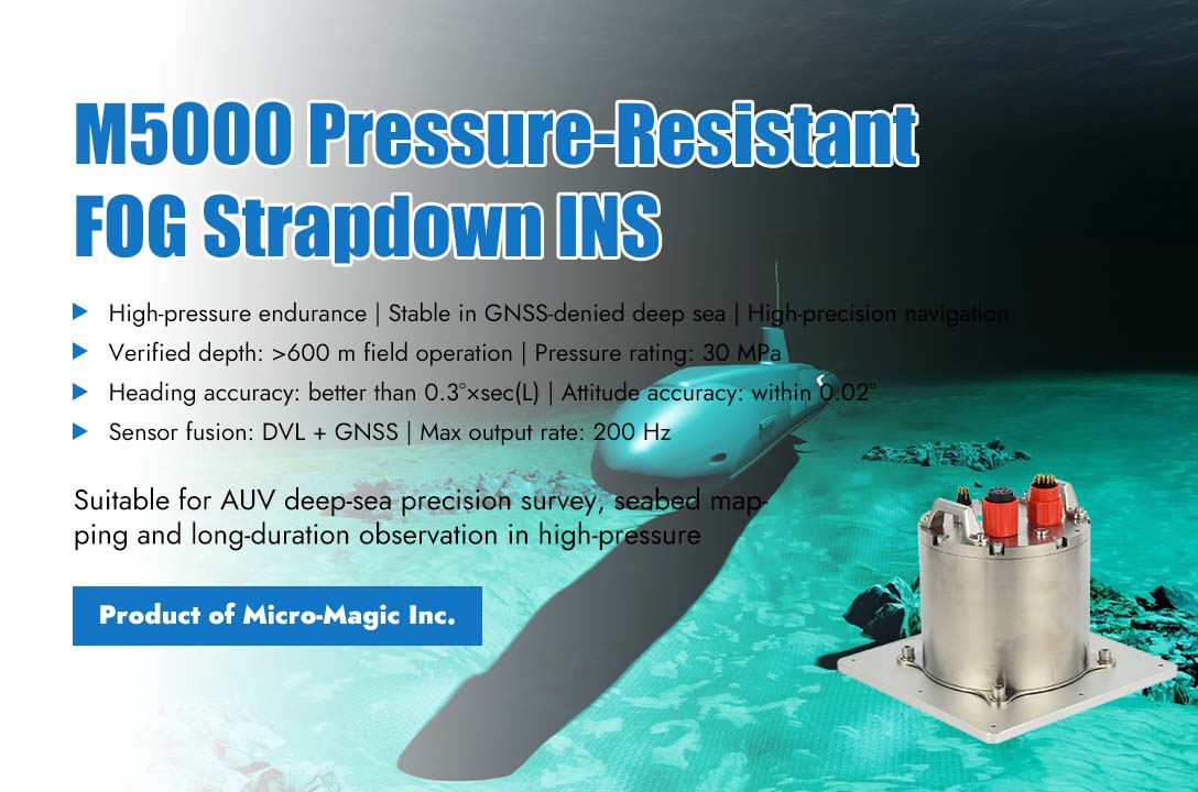
In the recently completed comprehensive deep-sea testing of a certain type of autonomous underwater vehicle (AUV), the M5000 pressure-resistant fiber optic strapdown inertial integrated navigation system developed by Micro-Magic Inc demonstrated excellent performance, successfully enabled the AUV platform to accomplish high-precision topographic mapping and prolonged continuous observation missions in 100-meter-class deep-water zones. With its excellent navigation accuracy and strong pressure resistance, the system provides reliable navigation support for deep-sea exploration equipment. In this test, the AUV was required to complete multiple dives within 15 working days, with a maximum operating depth exceeding 600 meters. Under extreme conditions such as high pressure, low temperature, and no satellite signal, the M5000 system operated stably throughout the entire process, without any data interruptions or accuracy degradation. An ocean technology expert involved in the project stated, "Deep-sea exploration has extremely stringent requirements for the accuracy and reliability of navigation systems. The M5000 can maintain a heading accuracy better than 0.3°×sec(L) and a stable attitude measurement accuracy within 0.02° even in deep-water areas where satellite signals are completely lost, providing crucial support for us to obtain high-confidence seabed topography data." As a navigation system specifically designed for deep-sea environments, the M5000 excels in pressure resistance. Its housing adopts a pressure-resistant structural design, maintaining full sealing performance under a static water pressure of 30MPa, equivalent to withstanding a pressure of 3000 meters depth. During the testing process, the system underwent nearly a hundred rapid cycles of ascent and descent, with neither its structural integrity nor electrical performance being affected. Furthermore, within the actual operating temperature range, the system effectively mitigates the impact of temperature drift on sensor accuracy through a built-in temperature compensation algorithm. In terms of data fusion and output, the M5000 system demonstrates excellent engineering applicability. The system integrates a three-axis fiber optic gyroscope and a quartz flexible accelerometer, enabling deep data fusion with multiple sensors such as Doppler Velocity Log (DVL) and GNSS receivers, with a maximum output frequency of 200Hz. Even in the event of a temporary DVL data interruption, the system can maintain stable computation through pure inertial navigation mode, ensuring that the AUV does not "lose its way" in complex hydrological environments. "The M5000 is not just a navigation unit, it serves as the 'eyes' and 'steering wheel' of the AUV in deep waters," said the project manager of Micro-Magic Inc. "We have optimized the filtering algorithm and error compensation model specifically for deep-sea applications, ensuring high accuracy consistency even during long-term operations. The success of this trial verifies our technical expertise and engineering capabilities in the field of high-precision navigation for deep seas."
Read More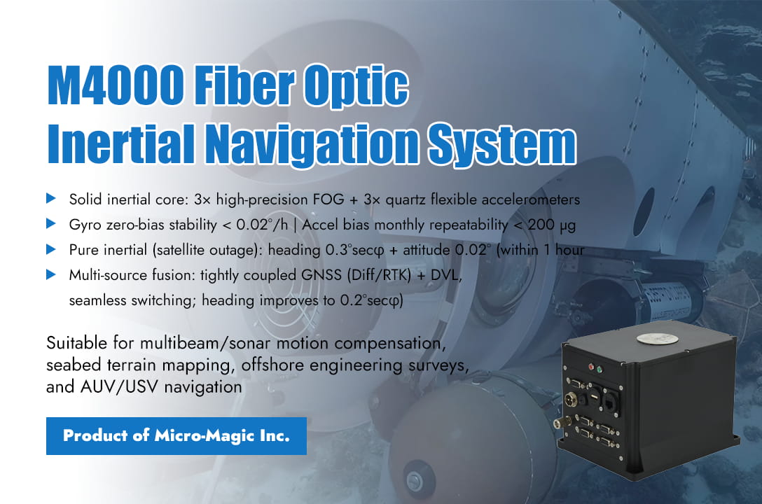
The core challenge in marine surveying lies in accurately determining the position, attitude, and motion state of the survey platform in open ocean environments where stable external references are lacking, thereby providing a stable spatial reference for detection equipment such as sonar. Traditional GPS+gyrocompass solutions can function under calm sea conditions, however, once encountering rough seas, the rolling, pitching, and heaving movements of the vessel can severely interfere with measurement accuracy, not to mention in complex submarine canyons or areas with electromagnetic interference, where GPS signal interruptions can bring the entire survey mission to a standstill. The M4000 Fiber Optic Inertial Navigation System, developed by Micro-Magic Inc, was specifically designed to address this critical pain point. The outstanding performance of the M4000 system begins with its solid fiber optic inertial core. The system integrates three high-precision fiber optic gyroscopes and three quartz flexible accelerometers internally, forming a stable and reliable autonomous sensing foundation with gyroscope's zero bias stability better than 0.02 °/h and accelerometer's bias monthly repeatability less than 200ug. This foundation enables the system to maintain a heading accuracy of 0.3°secφ and an attitude accuracy of 0.02° within 1 hour even in pure inertial mode with satellite signal interruption, providing a continuous and uninterrupted attitude reference for surveying operations and ensuring the spatiotemporal continuity of data acquisition. The true technological breakthrough is reflected in its powerful multi-source information fusion capability. The M4000 is not simply a stack of sensors, but a smart integrated navigation system with fiber optic inertia as the core, deeply coupled with GNSS satellite navigation and DVL Doppler odometer. When the satellite guidance signal is good, the system tightly combines with built-in or externally connected GPS (supporting differential and even RTK) to effectively correct accumulated inertial errors, improve heading accuracy to 0.2°secφ, and provide high-precision real-time position and velocity information. More importantly, in the face of the challenge of satellite navigation signal loss caused by underwater, fjord or complex sea conditions, the system can seamlessly integrate DVL, continuously suppress navigation error divergence using bottom or water velocity information, and ensure uninterrupted navigation solutions and accuracy during critical tasks. The ability to intelligently adapt and smoothly switch between "satellite navigation combination" and "pure inertia" modes gives surveying vessels or underwater vehicles the freedom to operate in all weather and sea conditions. In response to the precise perception requirements of vertical motion in marine surveying, the M4000 has specifically optimized its heave measurement function, with an accuracy of up to 5 centimeters or 5% heave amplitude. It can effectively separate the ship's own motion from wave disturbances, providing crucial motion compensation for multi beam depth measurement data and directly improving the quality of seabed terrain models. At the same time, the system takes into account the convenience and stability of engineering applications. Built in 32GB storage card can record complete navigation data for a long time and remotely read it through the network; Rich configurable interfaces and multi-channel synchronous pulse outputs enable it to flexibly connect to various surveying sensors and ensure data spatiotemporal synchronization. Its embedded IE configuration interface makes device control and parameter binding (such as installation deviation and lever arm compensation) more intuitive and convenient, greatly reducing the technical threshold for system integration and maintenance. From extensive terrain scanning in vast sea areas to precise underwater engineering investigations, and from precise positioning of surface surveying ships to reliable navigation of autonomous underwater vehicles, The M4000 fiber optic inertial navigation system, with its high-performance inertial core, deep fusion integrated navigation strategy, and highly engineered design, is becoming a key enabler for improving the quality and operational efficiency of marine surveying data. It not only represents the advancement of precision instruments, but also signifies the powerful ability to provide all-weather, highly reliable, and integrated solutions in the field of high-end ocean navigation and positioning, laying a solid technological foundation for managing the ocean and expanding blue territories.
Read More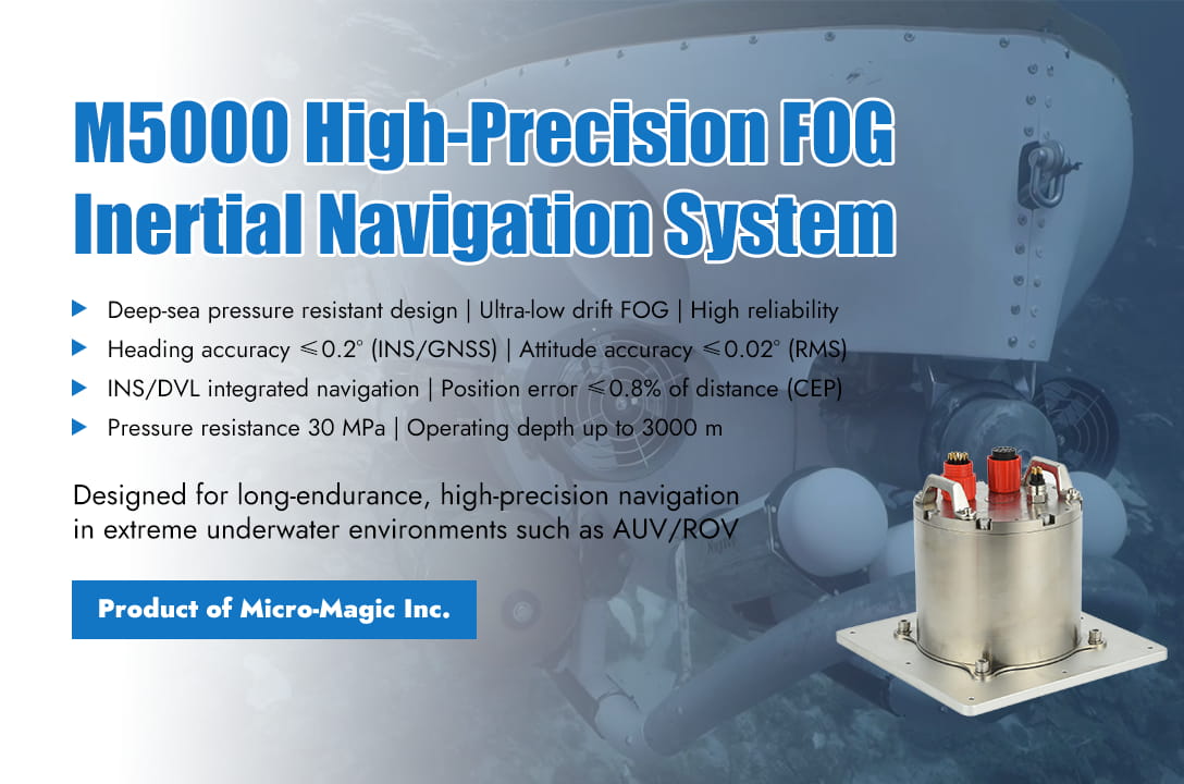
Deep sea exploration faces severe challenges such as high pressure, darkness, complex electromagnetic environments, and long endurance operations. In equipment such as unmanned deep-sea submersibles and underwater mapping platforms, high-precision and high reliability inertial navigation systems (INS) are the core to ensure the success of missions and the key technology to achieve autonomous, precise, and long-term underwater operations. Taking the M5000 pressure resistant fiber optic gyroscope (FOG) strapdown inertial navigation system produced by Micro Magic as an example, it has become the core navigation solution for deep-sea vehicles (such as AUV/ROV) with its deep-water pressure resistant design, multi-source fusion navigation capability, and high-precision sensors. Long-Endurance AUV Autonomous Exploration and Mapping AUVs need to conduct autonomous navigation for several hours or even days in thousands of meters deep trenches without GPS signals and with complex terrain, to perform large-scale underwater terrain mapping, resource surveys, or environmental monitoring. The system must have the ability to achieve long-term high-precision positioning, stable attitude output, and effectively integrate DVL velocity information to suppress accumulated errors in inertial navigation. The M5000 inertial navigation system integrates ultra-low drift FOG (0.01°/h) and high-precision accelerometer (0.02m/s²), ensuring extremely high attitude and heading accuracy during long-term underwater navigation, providing a stable platform and accurate geographic reference for surveying sensors (multi beam, side scan sonar). At the same time, the M5000 deeply integrated INS/DVL, significantly improving underwater positioning accuracy. A circular probability error of 0.8% of the range means that after sailing 10 kilometers, the positioning error is only about 80 meters (CEP), which is much better than pure inertial navigation. At a depth of 3000 meters and a pressure resistance of 30 MPa, it directly meets the depth requirements of most deep-sea AUV operations without the need for additional pressure tank protection. It is equipped with a 32GB SD card that can fully record the original inertial data and navigation solution results of the entire navigation process, making it easy to replay and analyze, evaluate accuracy, and optimize algorithms after the mission. ROV Precision Tasks and Station Keeping ROV perform precise operations such as equipment deployment, sample collection, and structural maintenance on the seabed, requiring ultra-high instantaneous attitude measurement accuracy and stability to ensure accurate spatial positioning of robotic arm operations; At the same time, it is necessary to quickly respond to the movement of the mother ship and maintain stable hovering. The M5000 provides near real-time precise spatial reference for ROV platforms and robotic arms with ultra-high attitude accuracy (≤0.02° RMS), which is the key to successful precision operations; 5cm or 5% surge accuracy, effectively measuring the vertical (heave) motion caused by the mother ship or ocean current, combined with high-precision attitude, assisting the ROV stability control system to achieve precise hovering and anti surge interference. Seafloor Observatories and Landers Observation platforms or landers that are deployed on the seabed for a long time need to monitor their own small posture changes (such as seabed geological activity, tilt caused by ocean currents), or provide accurate navigation information during deployment/retrieval. The M5000 inertial navigation system, with ultra-high attitude accuracy and stability, can sensitively capture small attitude changes of the platform, providing important data for geophysical or environmental monitoring; At the same time, M5000, with its independently developed anti electromagnetic interference algorithm, has strong anti-interference ability, which is particularly important in deep-sea hydrothermal areas or equipment intensive platforms where strong magnetic fields may exist; Built in GNSS receiver, quickly obtains accurate position information before deployment (on the water surface) or after recovery, and provides support for dynamic alignment. M5000 Performance Parameter Indicators Parameter M5000 Heading accuracy Inertial/satellite combination: ≤ 0.2° * sec (L) (RMS) Pure inertia: ≤ 0.3 ° * sec (L) (RMS) Attitude accuracy ≤0.02°(RMS) Positioning accuracy ≤0.8%D(CEP,INS/DVL组合) Heave accuracy 5cm or 5%H (Take the maximum value) Angular velocity accuracy 0.01°/s Angular velocity range ±500°/s Acceleration accuracy 0.02m/s^2 Acceleration range ±15g Alignment time ≤5min(Self-alignment) Navigation mode Inertial/satellite combination, pure inertia Operation temperature -40℃~+60℃ Protection grade Pressure resistance of 30 megapascals (3000 meters underwater) Conclusion The M5000 FOG strapdown inertial navigation system, with its deep-sea level pressure resistance capability, FOG based high precision and stability, depth optimized INS/DVL integrated navigation performance, compact and robust design, and rich functions for deep-sea applications, provides powerful navigation, positioning, and attitude reference support for key application scenarios such as autonomous exploration of deep-sea AUV, ROV precision operations, and underwater observation platforms. It is not only the "eyes" of the submersible to perceive its own state and position in a dark and high-pressure environment, but also the "nerve center" to ensure accurate and reliable detection data and successful execution of operational tasks.
Read Moreleave a message
Scan to Wechat :
