




Introduction
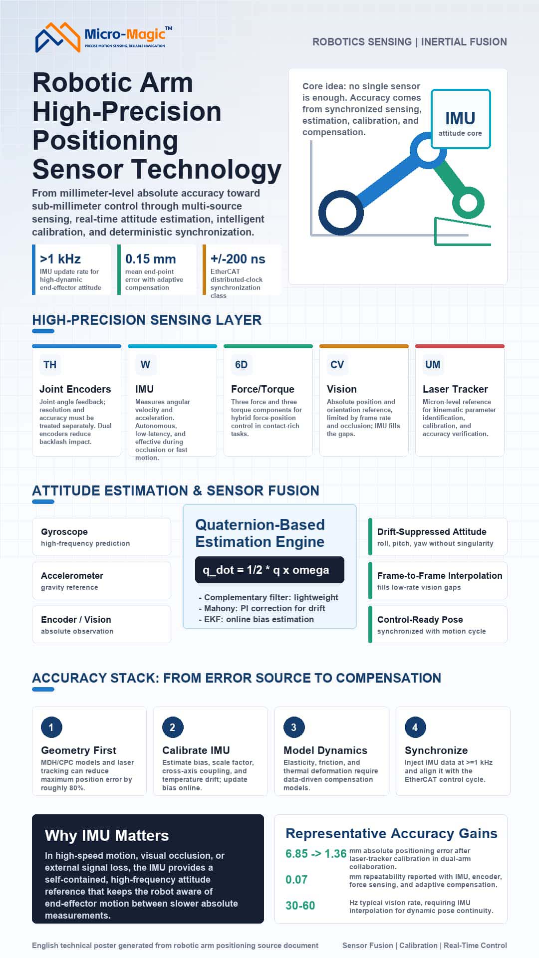
The absolute positioning accuracy of robotic arms—transitioning from the millimeter to the sub-millimeter scale—is constrained by multiple error sources: geometric parameter deviations (accounting for over 80%), sensor drift, elastic deformation, and communication jitter. Relying on single-sensor inputs or purely kinematic control is insufficient to meet the demands for dynamic, high-precision performance. Particularly during high-speed motion or in scenarios involving visual occlusion, the IMU—characterized by high-frequency operation, autonomy, and zero latency—serves as a cornerstone for pose estimation. Current technological trends favor a combination of multi-source sensor fusion, intelligent calibration, and high-real-time synchronization.
High-Precision Positioning and Sensing Technologies
Joint Encoders
Encoders determine the accuracy of joint angle feedback. Key metrics: resolution and accuracy must not be conflated. Optical encoders can achieve an accuracy of 5 arcseconds and 23-bit resolution; magnetic encoders offer robust resistance to contaminants; and high-end systems employ dual-encoder setups to eliminate the effects of backlash.
Inertial Measurement Units (IMUs)—The Core of Pose Estimation
IMUs integrate tri-axial gyroscopes and accelerometers to directly measure the angular velocity and linear acceleration of the end-effector. Gyroscope integration yields relative pose data with update rates exceeding 1 kHz—far surpassing vision systems—while accelerometers provide an absolute gravity reference during static states to calibrate integration drift. However, IMUs suffer from gyroscope integration drift (which can reach 30° after 10 minutes of inactivity) and accelerometer motion noise; resolving these issues is the central challenge addressed by sensor fusion. The unique advantage of the IMU lies in its independence from external signals and immunity to occlusion or latency-induced jitter, making it an irreplaceable autonomous sensor for high-frequency pose sensing at the robotic arm's end-effector.
Six-Axis Force Sensors
These sensors simultaneously measure three force components and three torque components, enabling hybrid force/position control. With an accuracy of 0.5% and repeatability error of 0.1%, they are utilized in contact-based tasks such as precision assembly and grinding.
Vision Systems
Configured as either "eye-in-hand" or "eye-to-hand," binocular vision systems can achieve positional accuracy of 1.2 mm and orientation accuracy of 0.15°, though they are limited by refresh rates (30–60 Hz) and occlusion issues. IMUs can be used to perform high-frequency pose interpolation between visual frames. External Calibration Equipment
A laser tracker (offering micron-level accuracy) serves as the reference tool for kinematic calibration, parameter identification, and accuracy verification.
Attitude Estimation and Sensor Fusion
Attitude Representation Methods
Euler angles are intuitive but suffer from the gimbal lock problem; degrees of freedom are lost when the pitch angle θ = ±90°.
Quaternions: q = q₀ + q₁i + q₂j + q₃k, satisfying q₀² + q₁² + q₂² + q₃² = 1.
Rotation operation: p' = qpq⁻¹
Quaternions are singularity-free and allow for smooth interpolation, making them the standard attitude representation in modern robotic systems. The core of IMU attitude estimation lies in solving the quaternion differential equation.
Fundamentals of IMU Attitude Estimation: Quaternion Differential Equation
Updating the quaternion using angular velocity ω = [ωₓ, ωᵧ, ωᵨ]ᵀ: q̇ = ½ q ⊗ ω
Discretization (first-order integration): qₖ₊₁ = qₖ ⊗ (cos(‖ω‖Δt/2), (ω/‖ω‖)sin(‖ω‖Δt/2))
This equation forms the basis for all IMU-based attitude estimation algorithms.
Complementary Filtering and the Mahony Algorithm
Complementary filtering fuses gyroscope integration (reliable at high frequencies) with accelerometer data (reliable at low frequencies):
θ(t) = α·θ_gyro(t) + (1-α)·θ_acc(t) (α typically ranges from 0.98 to 0.995)
The Mahony filter introduces PI closed-loop correction: gyroscope drift is compensated using an error term *e*—derived from the cross product of the accelerometer measurement *a_m* and the gravity reference *g_ref*—where *e* = *a_m* × *g_ref* and *ω_corr* = Kₚ*e* + Kᵢ∫*e*dt.
This method is computationally efficient and widely used in embedded systems for real-time attitude estimation of IMUs mounted on robotic arm end-effectors. Extended Kalman Filter (EKF)—Optimal Fusion Framework
The EKF uses gyroscope integration for prediction and accelerometer data (along with magnetometer and encoder-based forward kinematics) for observation. The state vector is defined as x = [qᵀ, b_gᵀ]ᵀ (attitude quaternion + gyroscope bias).
Prediction: $\dot{\hat{x}} = f(\hat{x}, \omega_m - b_g)$, $P = FPF^T + Q$
Update (using accelerometer observations of the gravity vector):
$K = PH^T (HPH^T + R)^{-1}$
$\hat{x}^+ = \hat{x} + K(z - h(\hat{x}))$
The EKF enables online estimation of gyroscope bias, significantly suppressing long-term drift. A tightly coupled EKF integrating IMU data with encoders or vision systems is the standard architecture for achieving high-precision pose estimation of robotic arm end-effectors.
Multi-source Fusion Strategy
Heterogeneous sensors are fused at the data, feature, or decision level. As a high-frequency internal sensor, the IMU is often combined with encoders (low-frequency, high-precision angular data), vision systems (absolute position but low frame rate), and 6-axis force sensors (contact information) to form either loosely or tightly coupled systems. Hybrid fusion is currently the mainstream approach for achieving micron-level precision, with the IMU providing an indispensable real-time reference.
Error Analysis and Calibration Compensation
Dominance of Geometric Errors
The classical DH model relies on idealized assumptions. Extended models (such as MDH and CPC) introduce additional geometric parameters. Calibration using a laser tracker can reduce maximum positional error by approximately 80%.
IMU Error Calibration
MEMS IMUs require calibration for bias, scale factors, cross-coupling, and temperature drift. Accelerometers are typically calibrated using the factory six-position method, while gyroscopes are calibrated using rate turntables. In robotic arm systems, kinematic constraints (such as static phase detection) can be utilized to update IMU bias online, effectively suppressing integration drift.
Laser Tracker Calibration Process
The robot traverses a set of predefined points while the laser tracker records end-effector coordinates; kinematic parameter deviations are then identified and compensated for. Following calibration, the absolute positioning accuracy of the dual-arm collaborative robot improved from 6.85 mm to 1.36 mm.
Non-geometric Errors and Dynamic Compensation
Non-geometric factors—such as joint elasticity, thermal deformation, and friction—cannot be adequately described by traditional models. Data-driven calibration methods (e.g., neural networks, Gaussian processes) enable the learning of error mappings from measured data. Compensation models integrating IMUs, encoders, and six-axis force sensors, combined with adaptive control, can reduce the mean end-effector positioning error to 0.15 mm and achieve a repeatability of 0.07 mm.
Real-time Communication and Multi-axis Synchronization
Multi-axis coordination requires the deterministic transmission of control commands. The EtherCAT industrial Ethernet bus employs an "on-the-fly processing" mechanism; its Distributed Clock (DC) synchronization error is as low as ±200 ns, with a jitter of ±5 μs. IMU data must be fed into the master controller at a rate of ≥1 kHz via high-bandwidth interfaces (such as SPI) and aligned with EtherCAT cycles to ensure strict frequency synchronization between attitude fusion and motion control.
Trends and Conclusions
High-precision robotic arm positioning is evolving toward a paradigm of multi-modal sensing, AI-based dynamic compensation, and real-time edge computing. As the core component for high-frequency, autonomous attitude sensing, the IMU—deeply integrated with encoders, vision systems, and force sensors—will play an increasingly indispensable role in high-speed, highly dynamic scenarios. Achieving absolute positioning accuracy at the sub-millimeter or even micron level requires coordinated optimization across four layers: sensing, computation, calibration, and synchronization.
leave a message
Scan to Wechat :
