T7000-I Fully Temp Compensated Ultra-High Precision Dual Axis Tilt Sensor Resolution 0.0005° Accuracy 0.001° Digital Output RS232/RS485/RS422/Ttl/Can
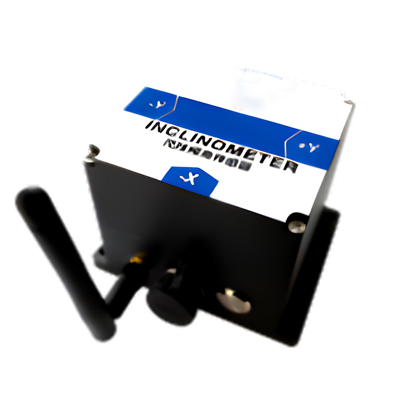
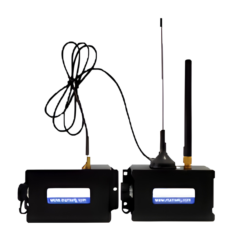
T7000-I-Modbus protocol is an ultra-low power consumption, small size, and full temperature compensation high-precision wireless inclination sensor. Powered by lithium batteries, based on the Internet of Things technology Bluetooth/Zigbee (optional) wireless transmission technology, all internal circuits have been optimized and designed using various measures such as industrial-grade MCU, three-proof PCB board, imported cables, and wide-temperature metal casing. The product has great long-term stability and small zero-point drift, and can automatically enter low-power sleep mode and getting rid of dependence on the use environment.
Part No, :
T7000-IOrder(MOQ) :
1Product Series and Parameters
| Parameter | Conditions | T7000-I | Unit |
| Measuring range | ±30 | ° | |
| Measuring axis | X, Y | ||
| Zero temperature drift | -40~85° | ±0.0005 | °/℃ |
| Sensitivity temperature coefficient | -40~85° | ≤150 | ppm/℃ |
| Frequency response | DC response | 100 | Hz |
| Resolution | 0.0005 | ° | |
| Accuracy | -40~85℃ | 0.001 | ° |
| Long term stability | -40~85℃ | <0.0016 | ° |
| Power-on start time | 0.2 | s | |
| Response time | 0.05 | s | |
| Radio frequency | 2460MHZ (default), 2405~2480 adjustable | ||
| Transmission distance | 1.6KM | ||
| Built-in battery capacity | 6000mAh | ||
| Average working hours | ≥55000 hours/time | ||
| Impact resistance | 2500g, 0.5ms, 3 times/axis | ||
| Anti-vibration | 10grms、10~1000Hz | ||
| Insulation resistance | ≥100MΩ | ||
| Waterproof level | IP67 | ||
| Weight | 475g (excluding packaging box) | ||
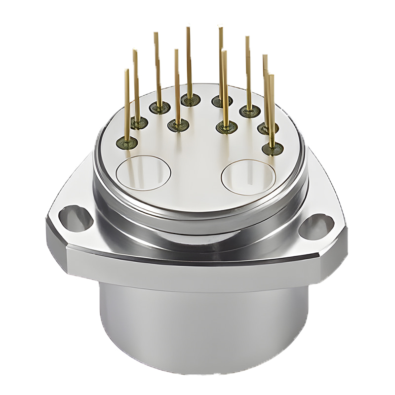
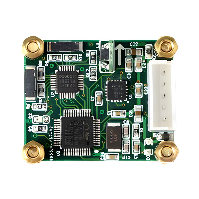
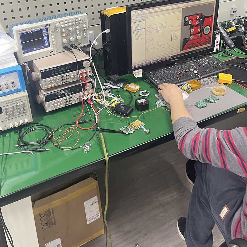
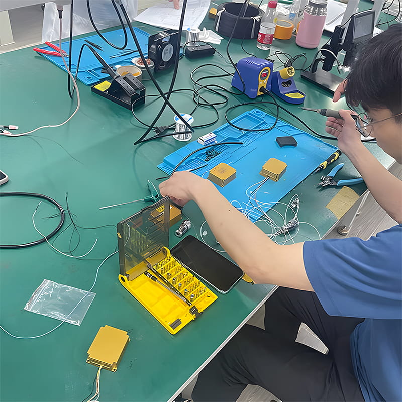
Production process
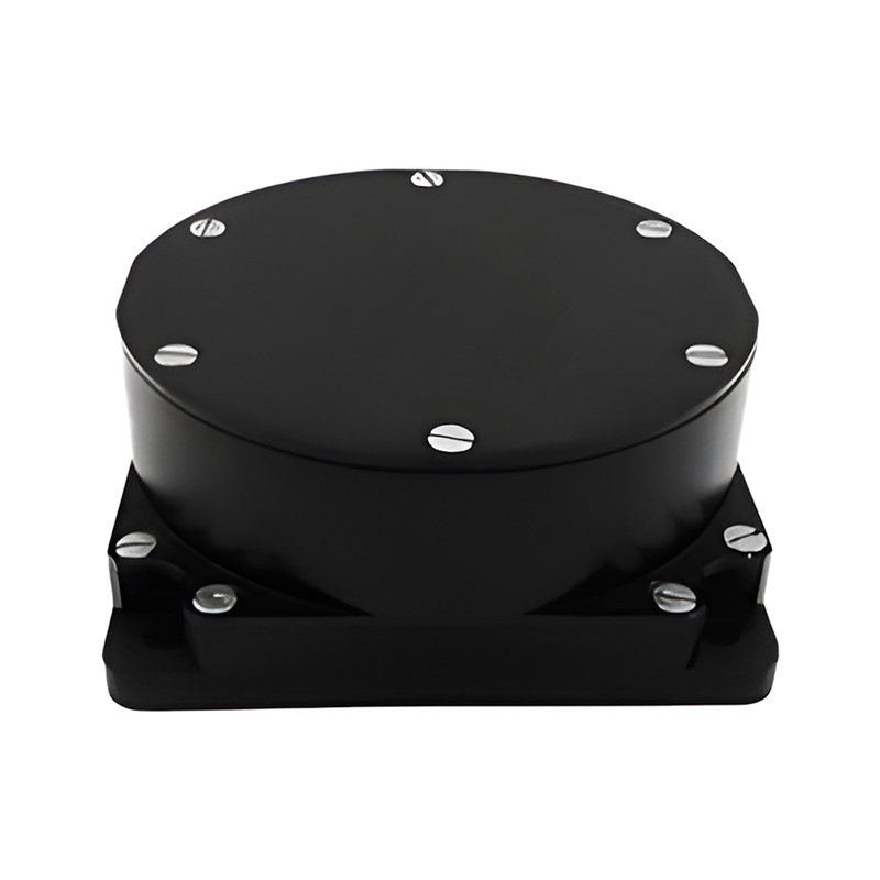
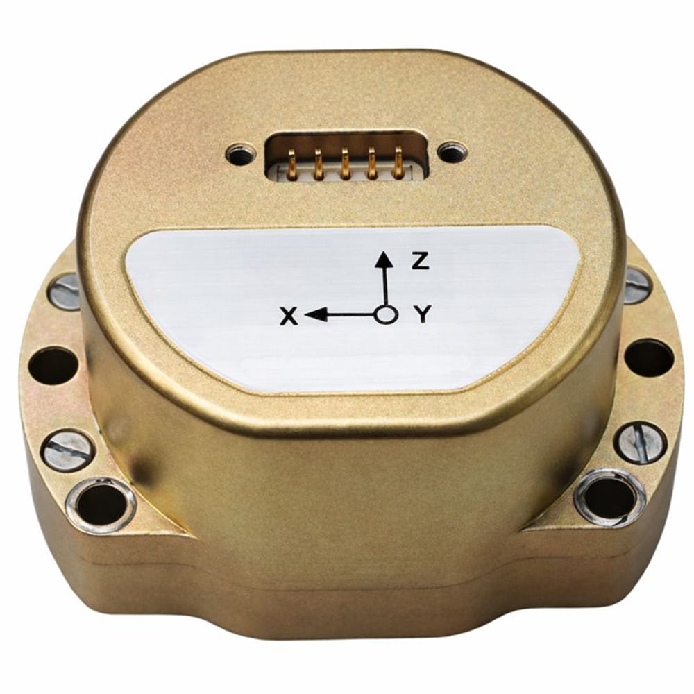
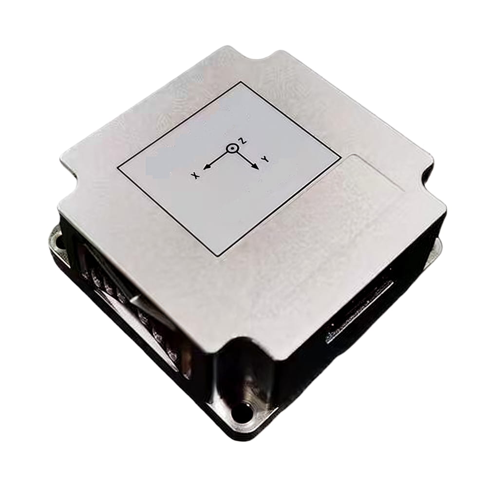
More similar products

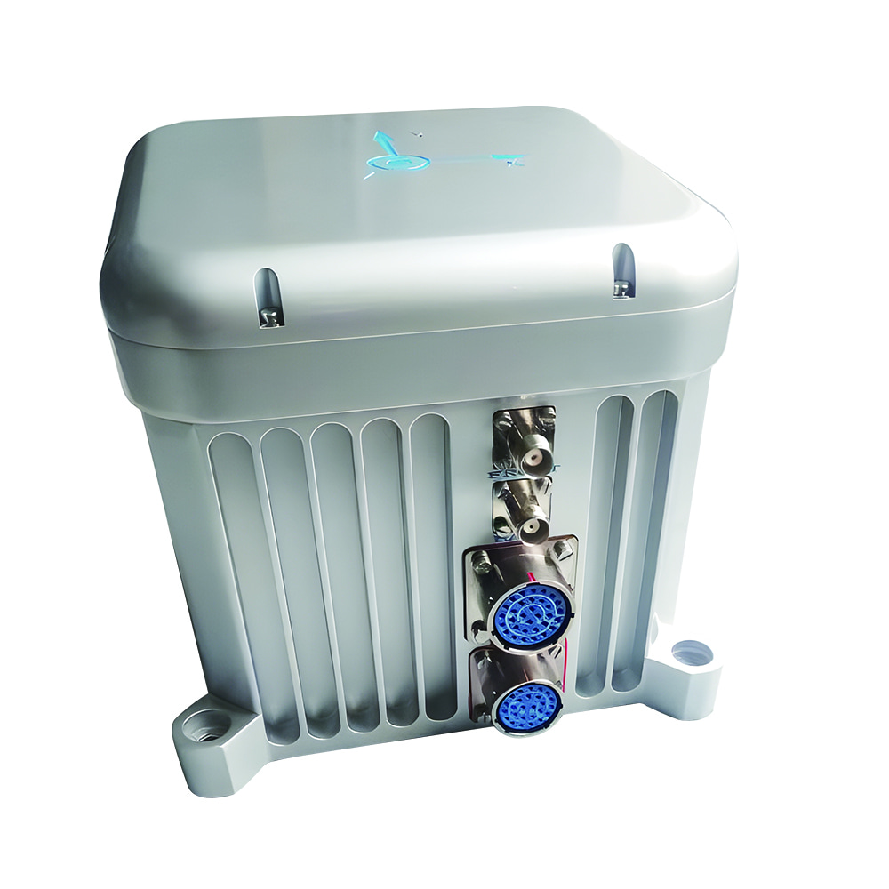
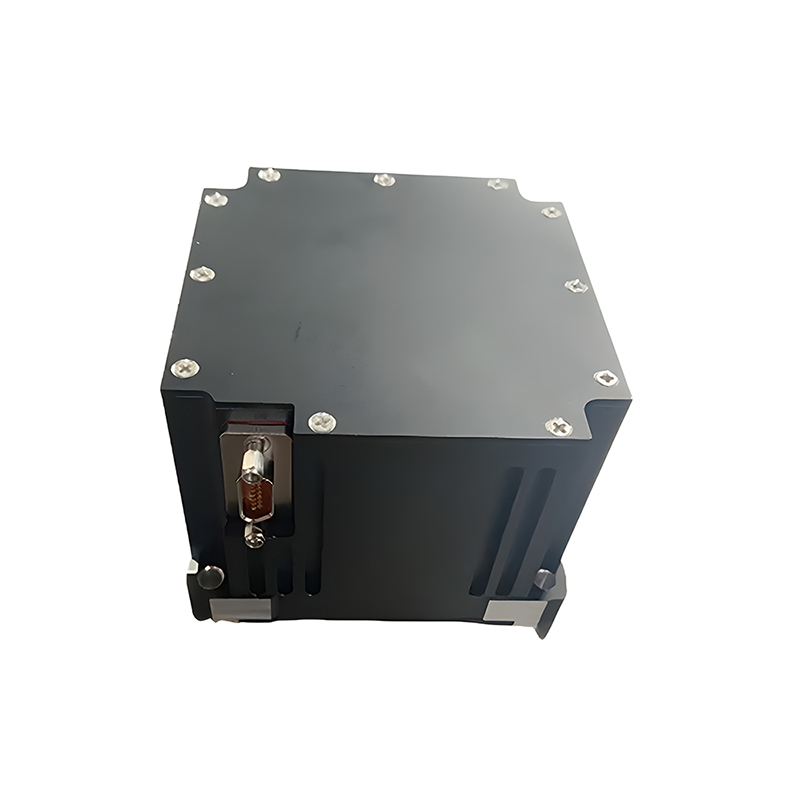
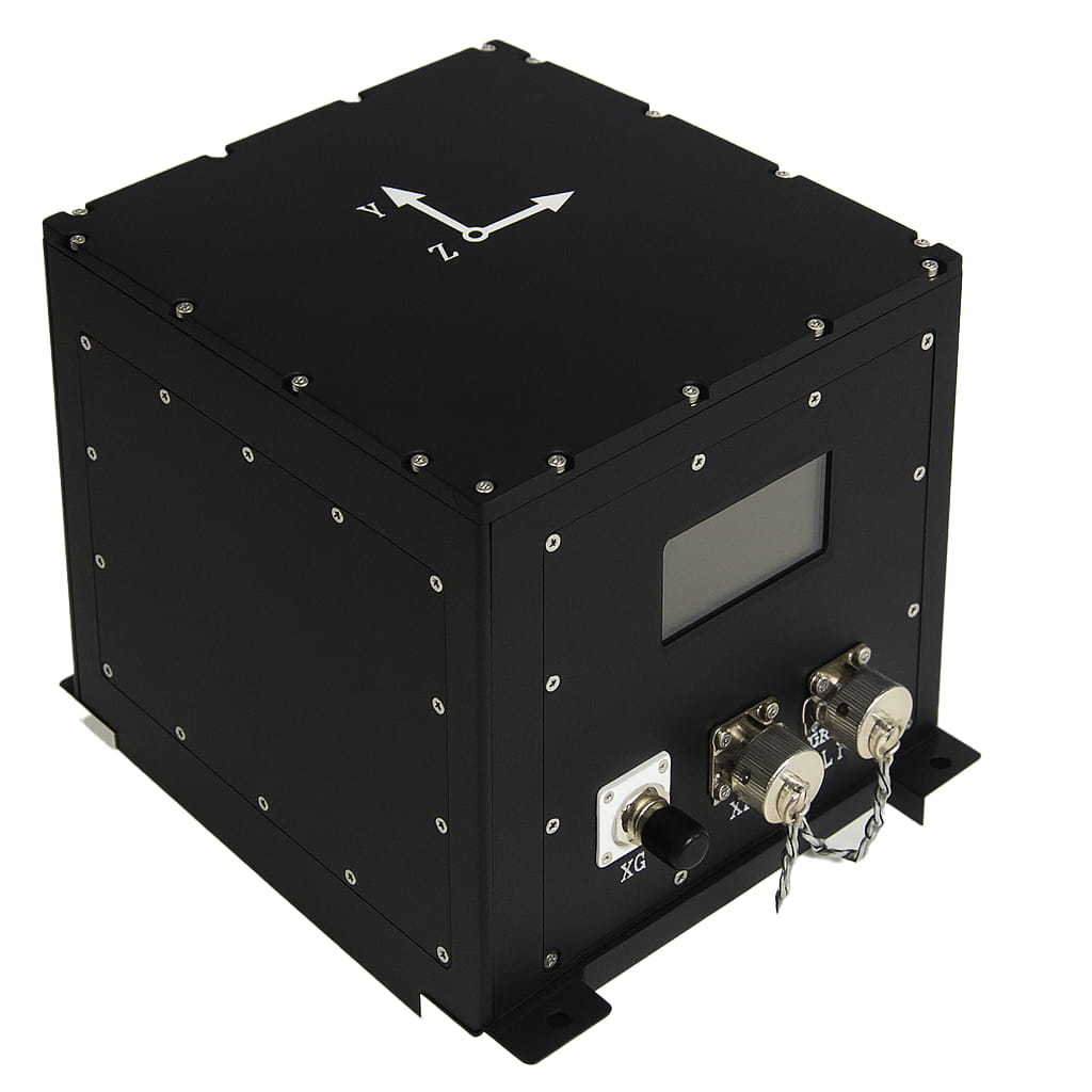
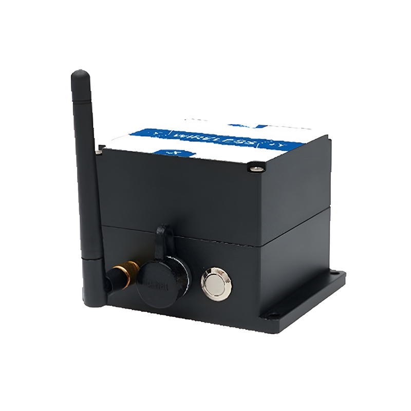
Product dimension

Product size: L94*W74*H64MM
The default is to install horizontally upward: when installing, keep the sensor installation surface parallel to the measured target surface; please refer to the rotation diagram for installation methods. If other installation methods are required, please refer to the schematic diagram of "Product Installation Method" and make a note when ordering.
Application Scenarios


FAQ

Xml Privacy Policy Blog Sitemap
copyright @ Micro-Magic Inc All Rights Reserved.
 Network Supported


 English