




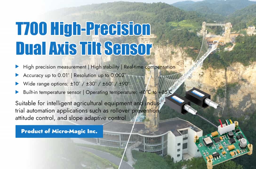
With the continuous improvement of agricultural machinery automation level, the requirements for equipment posture perception, safety control, and operational accuracy are also increasing. Micro-Magic Inc has launched the T700 series high-precision dual axis tilt sensor designed specifically for industrial control scenarios, providing a highly reliable and cost-effective attitude sensing solution for the field of agricultural machinery automation. The technical core of the T700 series comes from ADI's high-precision digital sensors, combined with Micro-Magic's independently developed n-order filtering algorithm and 16 bit A/D converter, to achieve real-time and accurate measurement of X-axis and Y-axis tilt angles. Its core technical indicators are impressive: full range accuracy up to 0.01°, resolution up to 0.002°, zero bias temperature drift not exceeding 0.008°/℃, sensitivity temperature coefficient controlled within 100ppm/℃, supporting multiple range options such as ± 10°, ± 30°, ± 60°, ± 90°, etc., which can meet the needs of different application scenarios. Of particular note is that the T700 series has a built-in temperature sensor that monitors real-time temperature changes in the working environment and dynamically compensates for sensor outputs through algorithms, ensuring high repeatability and stability of measurement data within a wide temperature range of -40℃ to +85℃. This feature has extremely high practical value for agricultural work environments with large temperature differences between day and night and obvious seasonal changes, ensuring that the equipment can provide reliable angle data under any climate conditions. The T700 series products can output various digital signals such as RS232, RS485, RS422, Modbus, and CAN, as well as analog signals like current and voltage. They are available in diverse forms, including complete units with a housing and bare boards without a housing. Additionally, slim-structure products suitable for confined spaces can be provided to meet special requirements. This facilitates system integration and easy installation for customers. With the continuous improvement of agricultural machinery automation level, the requirements for equipment posture perception, safety control, and operational accuracy are also increasing. Micro-Magic Inc has launched the T700 series high-precision dual axis tilt sensor designed specifically for industrial control scenarios, providing a highly reliable and cost-effective attitude sensing solution for the field of agricultural machinery automation. The technical core of the T700 series comes from ADI's high-precision digital sensors, combined with Micro-Magic's independently developed n-order filtering algorithm and 16 bit A/D converter, to achieve real-time and accurate measurement of X-axis and Y-axis tilt angles. Its core technical indicators are impressive: full range accuracy up to 0.01°, resolution up to 0.002°, zero bias temperature drift not exceeding 0.008°/℃, sensitivity temperature coefficient controlled within 100ppm/℃, supporting multiple range options such as ± 10°, ± 30°, ± 60°, ± 90°, etc., which can meet the needs of different application scenarios. Of particular note is that the T700 series has a built-in temperature sensor that monitors real-time temperature changes in the working environment and dynamically compensates for sensor outputs through algorithms, ensuring high repeatability and stability of measurement data within a wide temperature range of -40℃ to +85℃. This feature has extremely high practical value for agricultural work environments with large temperature differences between day and night and obvious seasonal changes, ensuring that the equipment can provide reliable angle data under any climate conditions. The T700 series products can output various digital signals such as RS232, RS485, RS422, Modbus, and CAN, as well as analog signals like current and voltage. They are available in diverse forms, including complete units with a housing and bare boards without a housing. Additionally, slim-structure products suitable for confined spaces can be provided to meet special requirements. This facilitates system integration and easy installation for customers. The T700 series provides technical support for the following typical scenarios through real-time perception and data output of device posture. ² Dump Truck Rollover Prevention Monitoring: T700 can monitor the tilt angle of the X-axis and Y-axis during the lifting process of the carriage in real time. When the tilt angle exceeds the set threshold, the system can trigger an audible and visual alarm or automatically interrupt the lifting action, effectively preventing rollover accidents caused by load deviation or uneven ground. ² Excavator Attitude Control: T700 can simultaneously monitor the horizontal posture of the fuselage and the tilt angle of the boom moving parts, providing real-time feedback data for the electronic control system. ² Slope Speed Adaptive Control: T700 can output the real-time tilt angle of the vehicle relative to the horizontal plane, and with the help of the vehicle control system, achieve speed adaptive adjustment based on slope. In the wave of integration between precise perception and intelligent decision-making, the Micro-Magic's T700 series tilt sensor, with its high reliability and flexible product form, has equipped agricultural machinery and equipment with "nerve endings" that can perceive terrain. This is not only a technological upgrade, but also a solid step towards digitalization and intelligence of agricultural productivity.
Read More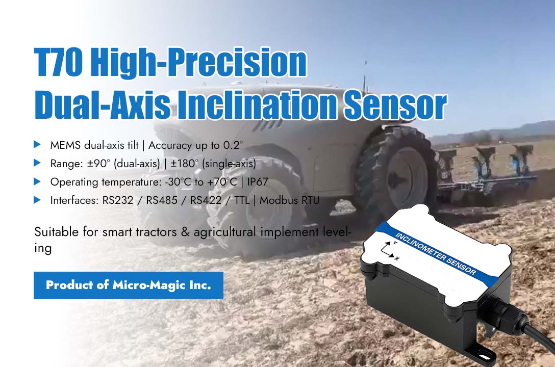
With the acceleration of agricultural modernization, intelligent agricultural machinery has become a crucial equipment for enhancing operational efficiency and ensuring operational safety. Recently, the T70 series high-precision dual-axis inclination sensor launched by Micro-Magic Inc has been successfully applied by customers for real-time monitoring and intelligent control of agricultural machinery posture, providing precise posture feedback for tasks such as sowing, fertilizing, and harvesting. The application of this sensor has significantly improved the consistency and precision of operations, facilitating more scientific and precise agricultural management. At the same time, it also provides reliable data support for the automation upgrade of agricultural machinery, further promoting the development of agricultural production towards intelligence and efficiency. The T70 series tilt sensor utilizes MEMS technology, featuring dual-axis inclination measurement capability with an accuracy of up to 0.2°. It supports a wide range of measurement options, including ±90° (dual-axis) and ±180° (single-axis). Its wide operating temperature range (-30°C to +70°C) and IP67 protection level ensure stable operation even in complex field environments. The sensor supports multiple output modes such as RS232, RS485, RS422, and TTL, and incorporates the Modbus RTU protocol, facilitating integration into various agricultural machinery control systems. In the customer's intelligent tractor project, the T70 inclination sensor is integrated into the latest generation of the tractor suspension system to monitor the horizontal and vertical inclination angles of agricultural machinery in real time. During actual operations, especially on sloping fields and uneven plots, agricultural machinery is prone to operational efficiency decline or even safety accidents due to imbalance in posture. By installing the T70 sensor at key positions on the suspension frame, the system can acquire the inclination data of the machinery in real time and automatically adjust the hydraulic suspension through the controller to achieve dynamic leveling. This not only improves the consistency and quality of operations such as sowing, fertilizing, and harvesting, but also significantly reduces operational difficulty and driver fatigue. The technical leader of the enterprise stated, "The high precision and strong anti-interference capability of the T70 series sensors make them highly suitable for agricultural environments with significant vibrations and drastic changes in temperature and humidity. Their dual-axis synchronous output function allows us to simultaneously monitor the attitude changes in both the forward and backward directions, as well as the left and right directions, enabling true three-dimensional attitude control." In addition, the sensor supports a "relative zero point" setting function, facilitating rapid calibration before operation; the automatic output rate can reach up to 50Hz, meeting the real-time response requirements for high-speed operations. These features collectively support a highly reliable and easily integratable intelligent attitude control system for agricultural machinery. As a leading designer and manufacturer of inertial sensors in China, Micro-Magic is committed to providing high-performance and high-reliability sensor solutions for various industrial and agricultural equipment. The successful application of the T70 series inclination sensors once again demonstrates the company's firm commitment to continuously empowering the upgrading of intelligent equipment through core inertial technology.
Read More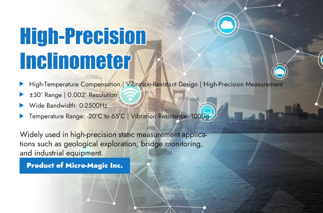
In the design of high-precision inclination measurement systems, error control is the key to determining system performance. This article combines existing research results and engineering practice to discuss implementation methods, error sources, analysis methods, and solutions from four aspects, providing reference for the design and optimization of high-precision inclination measurement systems. 1. How to use MEMS accelerometers to achieve tilt angle measurement The principle of measuring tilt angle with an accelerometer is based on the vector decomposition of gravitational acceleration. Under static or quasi-static conditions (without external acceleration interference), when the device tilts, the components of gravity acceleration on the three orthogonal axes (X, Y, Z) of the accelerometer will change. By measuring the proportions of these components, the tilt angle of the device relative to the direction of gravity can be calculated. As shown in the above figure: Among them, reflects the angle between the horizontal plane and the X-axis; reflects the angle between the horizontal plane and the Y-axis. 2. Analysis of main sources of error 1) Environmental interference error ⚪ Mechanical vibration: When sensors are installed in a vibrating environment, vibration can cause fluctuations in the output signal, such as in vehicle platforms or industrial equipment scenarios, where vibration may introduce a measurement deviation of ±0.5°. ⚪ Temperature drift: Temperature changes cause sensor zero drift, especially when the operating temperature exceeds the calibration range (such as -20℃~65 ℃), the error can reach 0.002°/℃. ⚪ Electromagnetic interference: Power fluctuations or external electromagnetic fields may interfere with the sensor signal chain, affecting the accuracy of analog-to-digital conversion. 2) Sensor self-error ⚪ Nonlinear error: The output of MEMS tilt sensors has a nonlinear relationship with tilt angle, sometimes, non-linear errors can reach a deviation of 0.1° within a range of ± 30 °. ⚪ Noise and resolution limitations: Improper processing of analog signals can lead to a decrease in effective resolution, such as insufficient ADC bits that may not be able to detect small signals at 0.175mV level. ⚪ Installation error: Uneven or loosely fixed base causes the sensor reference plane to be non-parallel to the measured surface, resulting in systematic deviation. 3) Dynamic interference If there is external acceleration (such as vibration or motion) on the device, the output of the accelerometer will contain dynamic acceleration components, resulting in tilt angle calculation errors. At this point, it is necessary to combine gyroscope or magnetometer for data fusion (such as Kalman filtering). 3. Error Solutions and Key Technologies 1) Environmental interference suppression technology a) Vibration reduction design: Use rubber pads to isolate the vibration source, or select sensors with dynamic filtering function. b) Temperature compensation: ⚪ Hardware level: Select MEMS chips with built-in temperature sensors to correct drift through real-time temperature acquisition. ⚪ Software level: Establish a temperature error curve fitting equation, such as using polynomial compensation algorithm to reduce the temperature drift accuracy to 0.002 ° @ -20~65 ℃. c) Power and signal isolation: High stability reference sources (such as LM236) are used to power the sensor, and decoupling circuits are designed to reduce the impact of power ripple. 2) Sensor signal optimization technology a) High precision signal chain design: ⚪ Use low-noise operational amplifiers (such as ICL7653) and differential conversion circuits (such as AD8138AR) to improve common mode rejection ratio and signal-to-noise ratio. ⚪ Using a 24-bit ∑-Δ type ADC (such as the built-in ADC in C8051F350), combined with a SINC3 filter to reduce noise and achieve a 20-bit effective resolution. b) Nonlinear correction: By subdividing the measurement range and fitting it with segmented sine curves, the nonlinear error is reduced from 0.11° to 0.0044°. 3) Install error correction system a) Dual sensor mapping method: By working together with the first inclination sensor (calibration reference) and the second sensor (to be calibrated) on the installation platform, a linear mapping relationship between the driving angle and the measurement angle is established to correct mechanical installation deviations. b) Horizontal calibration: Use a high-precision level to calibrate the installation surface, ensuring that the sensor reference plane is parallel to the measured surface, and fix the base with torque screws. 4) Dynamic Error Compensation Algorithm a) Multi sensor fusion: Integrating three-axis accelerometers and gyroscopes, predicting dynamic tilt angles through Kalman filtering or LSTM algorithms, and increasing update rates to over 100Hz. b) Optimization of the catenary model: Based on the dynamic deformation of the wire, the catenary equation is used to adjust the safety threshold in real-time in combination with environmental parameters (wind speed, temperature), reducing the misjudgment rate to below 0.3%. 4. Typical application cases and verification 1) Static high-precision measurement system The SOC based inclination measurement system (T7000-H series) achieves a maximum absolute error of 0.005° and a relative error of <0.02% through temperature compensation and curve fitting, and has been applied in geological exploration and bridge monitoring. 2) Explosion proof and earthquake resistant tilt angle sensor The T70-B series tilt sensor is designed for the field of explosion-proof hazardous chemical measurement. The internal MCU, MEMS tilt module, power circuit, and output circuit have been optimized through protective design to ensure optimal performance under extreme working conditions and long-term measurement environments. The measurement accuracy can reach 0.01°. 3) Wireless transmission tilt sensor T7000-I wireless tilt sensor is designed for industry applications where users have no power supply or real-time dynamic measurement of object posture and angle. Powered by lithium batteries, based on IoT technology such as Bluetooth and Zigbee (optional) wireless transmission technology, with industrial grade design, it has good long-term stability and small zero drift. It can automatically enter low-power sleep mode, thus eliminating dependence on the usage environment. 5. Future Development Trends 1) Intelligent compensation: Utilizing AI algorithms (such as neural networks) to adaptively correct multi-source errors and reduce reliance on manual calibration. 2) Integrated design: Integrating sensors, signal conditioning, and processing units into a single chip to reduce costs and improve reliability. 3) Multi physics field coupling analysis: Combining mechanics, thermodynamics, and electromagnetics models to achieve full condition error prediction. Through the above technological path, high-precision inclination measurement systems are expected to achieve wider applications in fields such as aerospace, intelligent equipment, and infrastructure monitoring.
Read More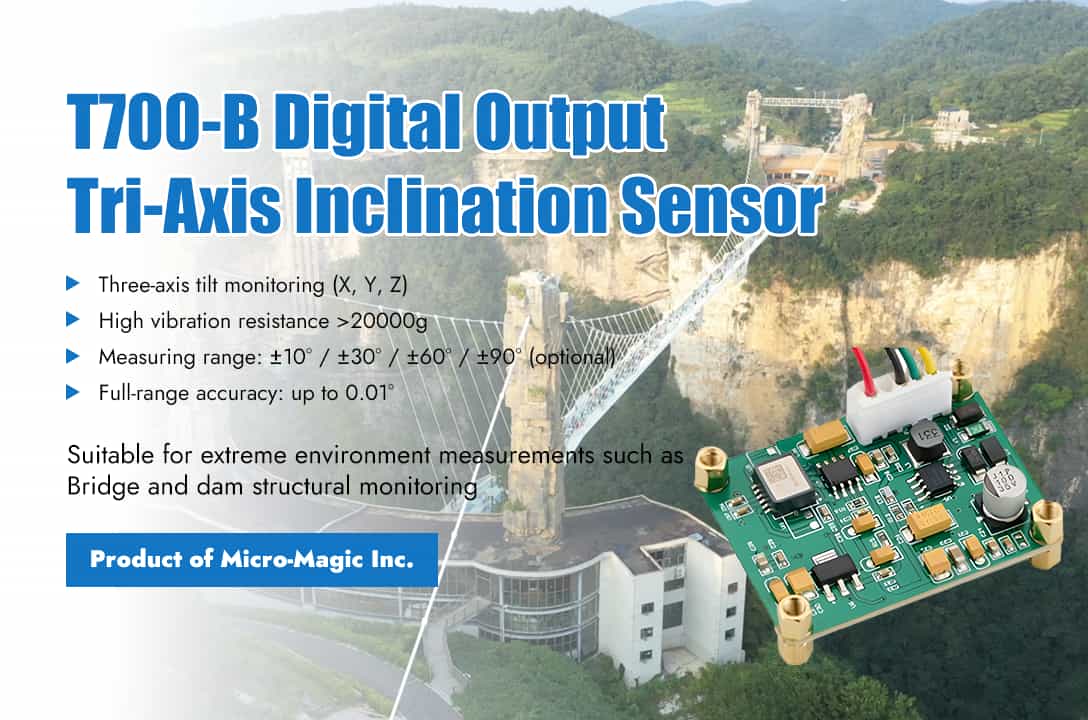
Tilt angle sensors play a crucial role in bridge monitoring, mainly used to measure changes in the tilt angle of bridge structures or their key components relative to the direction of gravity. These minor changes are often important indicators of the health status, load response, foundation settlement, or potential diseases of bridge structures. 1. Main Application Scenarios → Bridge pier/tower tilt monitoring Monitor whether there is slow and uneven settlement of the bridge pier foundation, which may cause the bridge pier to tilt. By using tilt sensors to continuously record angle changes for a long time, trend data can be provided. Real time monitoring of changes in verticality or preset angles during the construction of bridge piers/towers to ensure construction accuracy. → Bearing Displacement and Rotation Monitoring Monitor the rotation angle of bridge bearing under actual load. Abnormal changes in rotation angle may indicate aging, failure, or abnormal constraints of the bearing. By measuring the relative inclination angle between the top and bottom plates of the bearing, combined with the design parameters of the bearing, the sliding displacement of the bearing can be indirectly calculated. → Main Girder Alignment and Deformation Monitoring Although direct deflection measurement typically employs displacement transducers or levels, installing inclinometers at specific locations (e.g., mid-span, pier tops) enables monitoring of rotation changes in girder cross-sections. By integrating these angular measurements with geometric parameters of the girder (such as length), the relative deflection trend at these positions relative to reference points can be calculated. This approach is particularly valuable for long-term structural health monitoring (SHM) and large-span bridges. → Cable Tower/Arch Rib Deformation Monitoring:This process monitors angular changes in cable-stayed bridge towers or arch bridge ribs under load using inclinometers, assessing their global structural stability and deformation status. 2. Advantages of MEMS Tilt Sensors in Bridge Monitoring MEMS tilt sensors are small in size, light in weight, easy to install on structural surfaces or embedded in specific parts, and have minimal impact on the structure itself; MEMS tilt sensors have low cost and lower unit price compared to traditional high-precision tilt meters or fiber optic sensors, making it economically feasible to deploy sensor networks on a large scale and in a dense manner, thereby obtaining more comprehensive structural state information; MEMS tilt sensors have low power consumption and are particularly suitable for wireless sensor networks powered by batteries or energy harvesting, enabling long-term, unmanned monitoring. MEMS tilt sensors are easy to integrate and digitize, typically outputting digital signals directly (such as I2C, SPI, RS485), making it convenient to integrate with data collectors and wireless transmission modules to build automated monitoring systems; MEMS tilt sensors are easy to install and the installation process is relatively simple, usually only requiring a fixed base or magnetic attraction. MEMS tilt sensors have strong dynamic response capabilities, and some high-performance MEMS sensors have sufficient bandwidth to monitor the dynamic response of structures (such as tilt changes caused by vibration) Key Considerations in Applications Bridge monitoring usually requires high accuracy (better than 0.01 ° or even 0.001 ° level) and stability. Although MEMS technology continues to advance, its long-term drift and temperature sensitivity remain challenges, especially when pursuing high-precision applications. It is necessary to carefully select sensor models that meet accuracy requirements and consider temperature compensation and regular calibration strategies. The deformation of bridge structures usually does not change much in angle (often within the range of a few tenths of a degree to a few degrees), but sensors need to have high resolution and high linearity in a small range. At the same time, it is also necessary to consider the larger angles that extreme events (such as strong earthquakes) may produce. Sensors need to be able to withstand drastic temperature changes, humidity, vibration, and possible electromagnetic interference in the bridge environment. Need to choose industrial grade or reinforced packaging products. Tilt angle measurement refers to the angle between the sensor body and the direction of gravity. Therefore, the flatness, stability, and rigid connection with the measured structure of the sensor installation surface are crucial. Any slight deformation or looseness on the installation surface will directly affect the measurement results. Use Case Micro-Magic Inc has produced a series of MEMS tilt sensors to meet the needs of various application scenarios. Including 70 series, T700 series, T7000 series. All series of products are based on industrial design standards, covering both single axis tilt sensors and dual axis tilt sensors. Signal output includes digital and analog (current, voltage) outputs. The measurement accuracy covers the range of medium to high precision. All products support or can be customized with RS232/RS485/RS422/TTL/CAN/MODBUS communication protocols. Micro-Magic Inc has also produced a series of single board tilt sensors, which are convenient for customers to integrate into their own systems. For the special scenario of bridges and dams, Micro-Magic Inc has also launched a series of wireless tilt sensors,. Powered by lithium batteries and based on IoT technology Bluetooth and Zigbee (optional) wireless transmission technology, it avoids application limitations caused by wiring. Conclusion: MEMS tilt sensors, with their unique advantages, provide an economical, efficient, and easy to deploy local angle monitoring method for bridge structural health monitoring. It plays a critical role in monitoring areas such as pier inclination, bearing rotation, and deformation trends of main girders, especially suitable for large-scale deployment and long-term automated monitoring. With the advancement of technology and the improvement of data processing capabilities, its application in bridge monitoring will become more in-depth and intelligent. T700-A T700-B T7000-J
Read More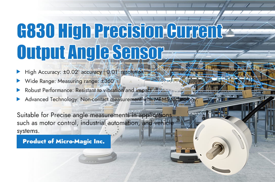
In the field of magnetic sensing technology, three-axis Hall sensors are sparking a precision revolution. This type of sensor achieves true three-dimensional spatial magnetic vector measurement by simultaneously detecting the magnetic field strength in the X, Y, and Z axes, completely breaking through the limitation of traditional single axis Hall sensors that can only detect vertical magnetic fields. The core technology lies in depositing special magnetic flux concentration materials (IMC®) onto the surface of CMOS chips. Enable sensors to capture magnetic field components parallel to the chip surface, combined with high-precision signal chain processing, to achieve 360° full angle position detection. This non-contact measurement method avoids mechanical wear and significantly improves long-term stability and reliability in harsh environments, bringing unprecedented precision control capabilities to modern industry and consumer electronics. Core Technological Advantages: High Precision, Strong Robustness, and Flexibility ■ High Precision and Resolution: The resolution reaches 14 bits (digital signal), equivalent to a resolution of 0.022 °, which is much higher than traditional optical encoders. The typical linearity error is ±1°, and the accuracy is maintained at 10 bits (0.35 °) after temperature drift compensation. The G830 angle sensor even achieves 16 bit ADC accuracy, with an angle error of only 0.02 ° and a temperature drift of 0.002 °/C, reaching the international leading level. ■ Exceptional Environmental Robustness: With strong temperature adaptability, resistance to mechanical tolerances and stray magnetic fields, the working temperature range can reach -40 ° C to+160 ° C, and is insensitive to magnet eccentricity and air gap changes (± 50% tolerance). The third-generation technology can resist stray field interference of 4 kA/m (such as electric vehicle motor magnetic field) and eliminate external interference through differential algorithms. ■ System Integration and Cost Optimization: No PCB packaging, supports direct soldering solutions such as DMP-4 (dual-mode packaging) and SMP-3 (single-mode packaging), eliminates the need for PCB boards, improves EMC/ESD reliability, and reduces system costs. Flexible magnetic circuit design, compatible with various types of magnets with radial/axial magnetization (ferrite, neodymium iron boron, etc.), smaller size and no need for complex calibration. Application Reach: From Automotive Core to Industrial Frontiers In the field of automotive electronics, three-axis Hall sensors have penetrated into key nodes of power transmission: ■ Chassis and safety system: steering wheel torque/steering angle detection (EPS), electronic brake pedal position sensing, accuracy directly affects the stability control efficiency of the vehicle body. ■ Powertrain control: Electronic throttle body, EGR valve angle feedback, with an error of ± 1° to ensure precise emission control. ■ New electric architecture: motor rotor position detection (replacing photoelectric encoders), gearbox gear position sensor. The industrial sector is also experiencing a wave of innovation: ■ Robot joint coding: realizes the detection of robotic arm posture, real-time monitoring of collaborative robot joint angles (0.1° repeatability accuracy), and adapts to industrial environments with anti oil pollution characteristics. ■ Motor control: BLDC motor commutation angle detection, replacing optical encoders. ■ Heavy machinery equipment positioning: Crane arm angle sensing, forklift lifting height detection, agricultural machinery steering angle feedback, IP equivalent protection against dust and water vapor erosion. Three Axis Hall Angle Sensor Related Products Micro-Magic Inc has produced a series of angle sensor products based on three-axis Hall technology, ranging from low to high precision, from low to high cost. Each product undergoes calibration, reverse and anti pulse peak voltage protection, and long-term aging stability testing before leaving the factory. Each process is precise and rigorous, ensuring reliability under different working conditions and long-term use cycles. Angle Sensor Performance Indicators Parameter G803 G810 G830 Unit Measuring range 0~360 ° 0~360 ° 0~360 ° Temperature drift 0.02 0.01 0.002 Resolution 0.05 0.01 0.01 ° Accuracy 1 0.5 0.05 ° Impact resistance 20000g,0.5ms,3 times/axis Anti-vibration 10grms,2~2000Hz Noise 5mV Average working time ≥55000h Output Digital TTL, RS232, RS485, RS422, CAN optional Voltage 0~5V, 0.5-4.5V, 0~10V optional Current 0-20mA, 4-20mA optional Working temperature range -40~85℃ Conclusion The three-axis Hall angle sensor, with its non-contact, high-precision, and multi-dimensional technological advantages, is quietly reshaping the underlying architecture of multiple industries. With the breakthrough of technological bottlenecks, especially the improvement of anti-interference ability and the integration of edge intelligence, this technology will develop towards miniaturization and intelligence, providing a more reliable "spatial perception eye" for the era of Internet of Things.
Read Moreleave a message
Scan to Wechat :
