




Introduction
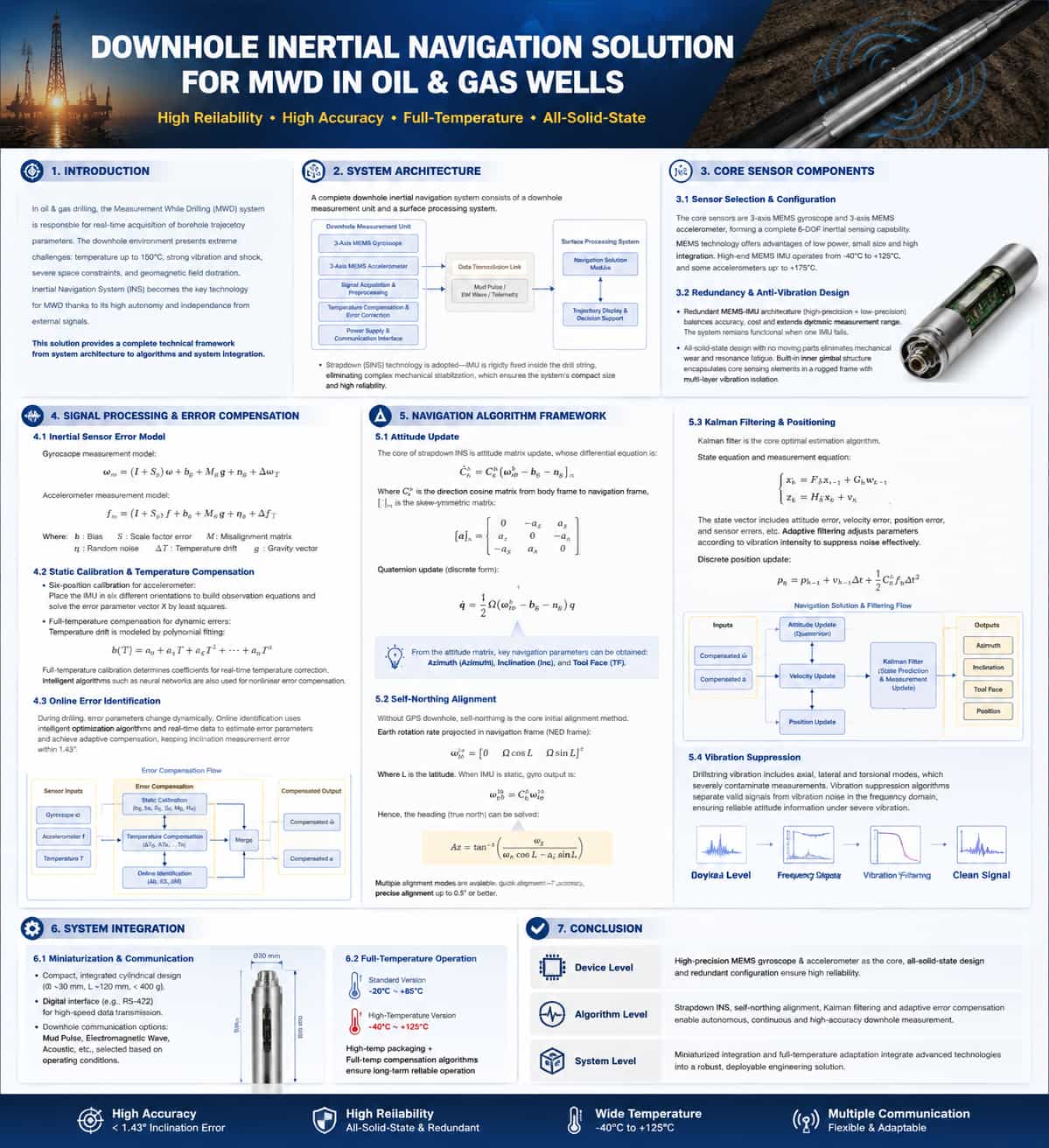
In oil and gas drilling engineering, Measurement While Drilling (MWD) systems perform the critical task of acquiring real-time borehole trajectory parameters. The downhole environment imposes extremely rigorous demands on navigation systems—including temperatures exceeding 150°C, continuous intense vibration and shock, severe spatial constraints, and significant geomagnetic field distortion—all of which create technical barriers for downhole navigation. Inertial Navigation Systems (INS) have emerged as a key technical approach for MWD due to their high level of autonomy and independence from external signals. This paper provides a technical analysis covering five aspects: system architecture, core components, error compensation, navigation algorithms, and system integration.
System Architecture
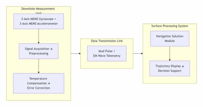
A complete inertial MWD system consists of a downhole measurement unit and a surface processing system. The downhole unit is installed within a drill collar near the drill bit and integrates an Inertial Measurement Unit (IMU)—comprising tri-axial gyroscopes and tri-axial accelerometers—along with signal acquisition circuitry, a power module, and communication interfaces. The surface system is responsible for data reception, navigation computation, borehole trajectory visualization, and decision support.
Current mainstream solutions employ strapdown inertial measurement technology, in which the IMU is rigidly mounted inside the drilling tool. By eliminating complex mechanical stabilization structures, this approach fundamentally enables system miniaturization and enhances reliability.
Core Sensor Components
Sensor Selection and Configuration
The core sensors of the LWD (Logging While Drilling) inertial navigation system consist of a tri-axial MEMS gyroscope and a tri-axial MEMS accelerometer, providing comprehensive six-degree-of-freedom inertial sensing capabilities. MEMS technology has become the mainstream choice due to advantages such as low power consumption, compact size, and high integration potential. High-end MEMS IMUs operate within a temperature range of -40°C to +125°C, with some accelerometers capable of withstanding temperatures up to +175°C.
Redundant Configuration and Vibration-Resistant Design
Redundant MEMS-IMU configuration is a key method for enhancing reliability. A typical dual-inertial-navigation architecture incorporates both high-precision and low-precision IMUs, balancing accuracy and cost while extending the dynamic measurement range. The system remains functional even if one sensor unit fails.
Regarding vibration resistance, the fully solid-state design contains no moving mechanical parts, fundamentally eliminating mechanical wear and resonance-induced fatigue. An internal platform structure encases the core sensing elements within a robust mount, utilizing a multi-layer design to absorb and dampen vibration energy.
Signal Processing and Error Compensation
Inertial Sensor Error Models
Measurements from MEMS inertial sensors contain various error components. The gyroscope measurement model is:
ω̃ = ω + b_g + s_g∙ω + M_g∙ω + n_g + ε_g(T)
The accelerometer measurement model is:
ã = a + b_a + s_a∙a + M_a∙a + n_a + ε_a(T) + g
Where: "b" = bias; "s" = scale factor error; "M" = installation error matrix;
"n" = random noise; "ε(T)" = temperature drift; "g" = gravitational acceleration vector.
Achieving high-precision measurement requires the calibration and compensation of each error term.
Static Calibration and Temperature Compensation
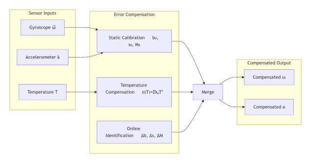
Static error compensation is performed during the factory calibration phase. Taking the six-position calibration of an accelerometer as an example, observation equations—$y = H \cdot X + v$—are established by placing the IMU in six different orientations.
The error parameter vector $X$ is then solved using the least-squares method.
Full-temperature-range compensation is critical for dynamic compensation. Polynomial fitting models are commonly used to characterize temperature drift:
$\varepsilon(T) = k_0 + k_1 T + k_2 T^2 + \dots + k_n T^n$
Fitting coefficients ($k_0, k_1, \dots, k_n$) are determined through full-temperature-range calibration experiments to enable real-time temperature correction. In recent years, intelligent algorithms—such as neural networks—have also been introduced to efficiently compensate for nonlinear errors.
Online Error Identification
Error parameters change dynamically during the drilling process, a scenario that traditional offline calibration struggles to address. Online error identification utilizes intelligent optimization algorithms and real-time data to dynamically identify error parameters and achieve adaptive compensation, thereby keeping the borehole inclination measurement error within 1.43°.
The complete error compensation process is as follows:
5. Navigation Algorithm Framework
5.1. Attitude Update
The core of strapdown inertial navigation computation is the update of the attitude matrix; its differential equation is:

 Let be the attitude transformation matrix from the carrier frame to the navigation frame.
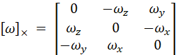
 The skew-symmetric matrix of the vector:
The discretization solution employs a quaternion update algorithm, and the quaternion differential equation is:
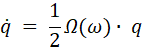
Three key navigation parameters—azimuth, inclination, and tool face angle—can be extracted from the attitude matrix.
5.2. Self-North-Seeking Initial Alignment
In the absence of GPS signals downhole, self-north-seeking serves as the core technology for initial alignment. The projection of the Earth's angular velocity of rotation onto the navigation frame (North-East-Up coordinate system) is:
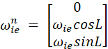
 ,
, corresponds to the local latitude. When the IMU is stationary, the gyro output is:

From this, the heading angle (relative to true north) is calculated:

The system offers multiple alignment modes: rapid alignment with an accuracy of approximately 1°, and precision alignment achieving 0.5° or better.
5.3. Kalman Filtering and Positioning
Kalman filtering is the core optimal estimation algorithm for the inertial navigation system; the state and observation equations are as follows:


The state vector comprises attitude errors
, velocity errors, position errors, and sensor errors. To address the downhole vibration environment, adaptive filtering is employed; parameters are dynamically adjusted based on vibration intensity to effectively suppress noise.
The discrete position recursion formula is:
leave a message
Scan to Wechat :
