




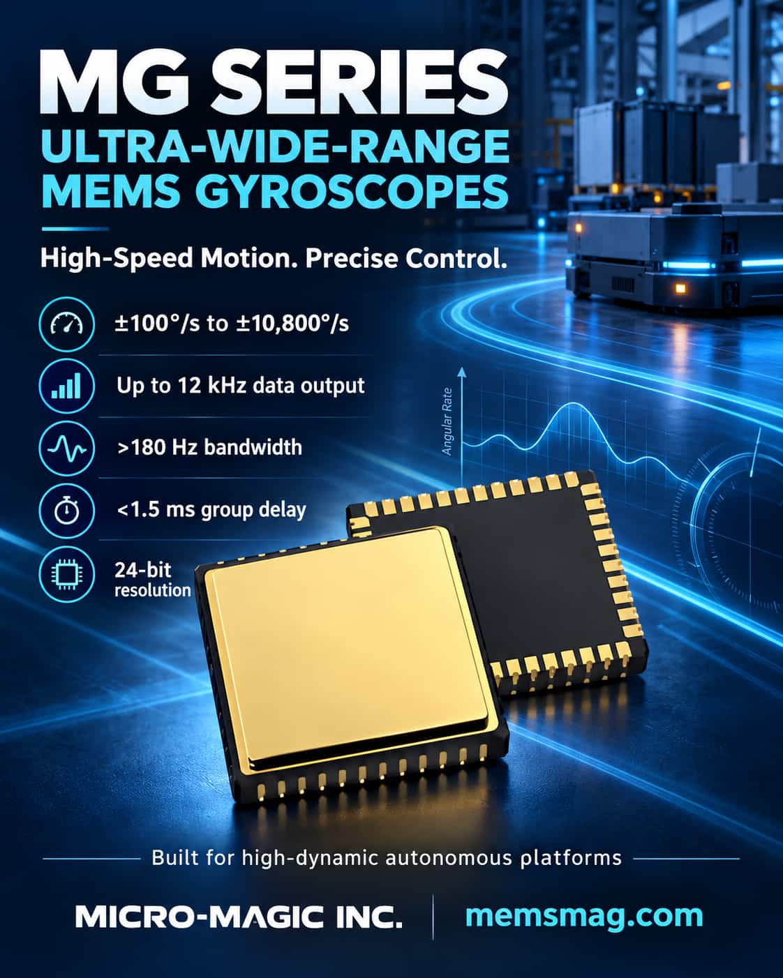
As unmanned systems evolve toward higher speed, greater maneuverability, and stronger autonomy, the bottleneck in motion control systems often lies not in algorithms but in whether front-end inertial sensors can promptly and accurately sense high angular rates. Conventional MEMS gyroscopes are prone to entering saturation or exhibiting noticeable delay during sharp turns of high-speed UAVs, off-road driving of unmanned combat vehicles, or rapid joint movements of robots. To meet these needs, the MG series ultra-wide-range MEMS gyroscopes developed by Micro-Magic Inc. extend the measurement range from ±100°/s to ±10800°/s and position ±4000°/s-class products as the primary measurement range for high-speed motion control. The core idea behind this series is not merely to pursue a wide range, but to maintain the dynamic quality required for closed-loop control across a wide range. The MG series adopts a 24-bit resolution architecture, with a maximum data output rate of up to 12kHz, group delay below 1.5 ms in most high-range models, and bandwidth above 180Hz. For ±4000°/s-class models, such as the MG-4001, bias instability is below 0.3°/h, angular random walk is below 0.25°/√h, broadband noise peak-to-peak is below 1°/s, and both g-sensitivity and vibration rectification error are below 1°/h/g. These specifications mean that the sensor can still provide angular rate information usable for attitude determination and stabilization control in rapid maneuvering and vibration environments. Environmental adaptability is another unavoidable dimension for unmanned platforms. The MG series supports an operating temperature range of -40°C ~ +85°C. Its vibration resistance reaches 18 grms, and its shock resistance is up to 500g/1ms. 5V supply and typical current consumption of 45 mA also make the series easy to integrate into unmanned systems with strict requirements on power consumption and power supply architecture. 750ms startup time makes it suitable for mission scenarios requiring rapid power-on readiness. The MG series is not a single model, but a family spanning multiple measurement ranges and accuracy grades. The low-range MG-101 and MG-102 target high-precision attitude measurement; mid-range models such as the MG-301 and MG-401 balance range and stability, making them suitable for general unmanned platforms; and the high-range MG-4001, MG-8001, and MG-10800 push the upper measurement limit to ±4000°/s, ±8000°/s, and ±10800°/s, respectively, offering options for high-speed rotation, high maneuverability, and extreme angular rate scenarios. This scalability enables designers to match sensors to actual motion profiles instead of making excessive compromises among range, accuracy, and cost. The value of the MG series lies in combining the two requirements of "wide range" and "suitability for control" in a single MEMS gyroscope. It is neither a coarse sensor that pursues range alone nor a high-precision device that can only operate at low speeds. As unmanned systems continue to evolve toward higher speed and greater autonomy, MEMS gyroscopes like the MG series - covering ranges of ±4000°/s and above while maintaining low latency, high bandwidth, and strong environmental adaptability - are becoming key foundational components for breaking through the bottleneck in high-speed motion control.
Read More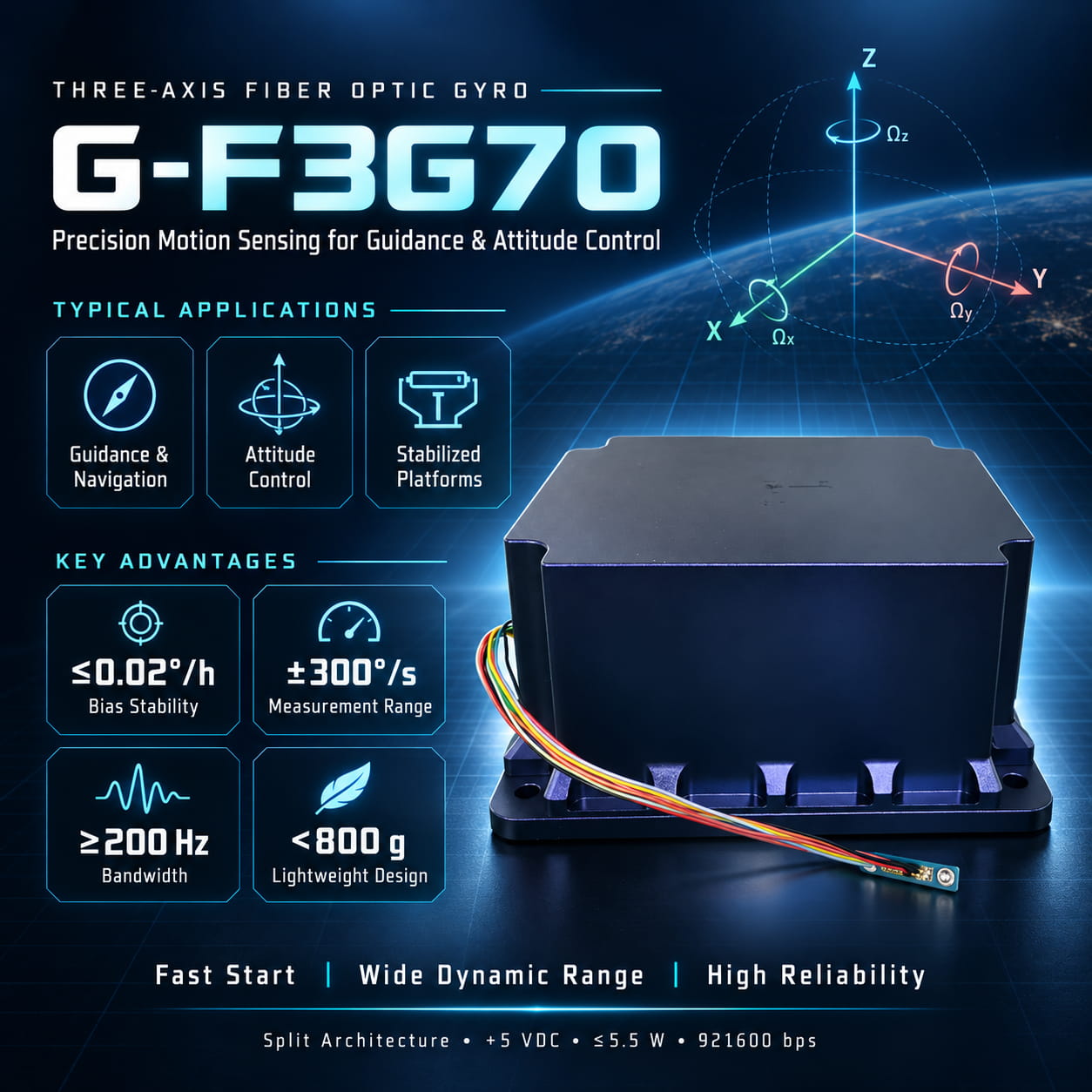
Core Application: Guidance and Attitude Control The G-F3G70 tri-axial fiber optic gyroscope (FOG) is specifically designed for medium-to-high precision navigation, guidance, and attitude control systems. It serves as a critical sensing core enabling precision strikes and flight control for tactical weapons such as small missiles and guided bombs. By integrating angular rate sensing capabilities across three axes, it accurately detects the carrier's 3D attitude changes and angular motion in real-time. It provides vital data to the flight control computer, ensuring the weapon platform maintains stable flight along its intended trajectory and strikes the target with precision. Technical Advantages: High Precision and High Reliability As an all-solid-state gyroscope, the G-F3G70 inherits the inherent advantages of fiber optic gyroscopes: rapid startup, wide dynamic range, and high reliability. Its superior performance fully meets the requirements of navigation and guidance-grade applications: · Excellent Bias Stability: The G-F3G70-C model achieves bias stability of ≤0.02°/h (10s smoothing), ensuring an accurate and stable attitude reference during long-duration flight missions. · High Dynamics and Sensitive Response: The product features a dynamic measurement range of ±300°/s and a bandwidth of ≥200Hz, enabling precise tracking of attitude changes during high-speed, high-maneuverability flight. Additionally, a threshold and resolution of ≤0.01°/h ensure the system's keen sensitivity to minute angular movements. · Harsh Environment Adaptability: It supports an operating temperature range of -45°C to +65°C and features a lightweight design (under 800g). Combined with the FOG's inherent shock and vibration resistance, it is ideally suited for demanding environments such as missile-borne applications. Ease of System Integration The G-F3G70 utilizes an integrated optical-electronic packaging design with a split-unit structure, resulting in a compact form factor and easy installation. The electronics module measures 60×60×24mm, while the sensor head measures Φ67mm×17.5mm. It includes clearly defined M3×4 and Φ2.7×8 mounting holes, facilitating integration into space-constrained weapon systems. The product operates on a standard +5V power supply with a steady-state power consumption of ≤5.5W, and outputs digitized angular rate and temperature data via a high-speed serial port (921600 bps, even parity), greatly simplifying the user's electrical and communication interface design.
Read More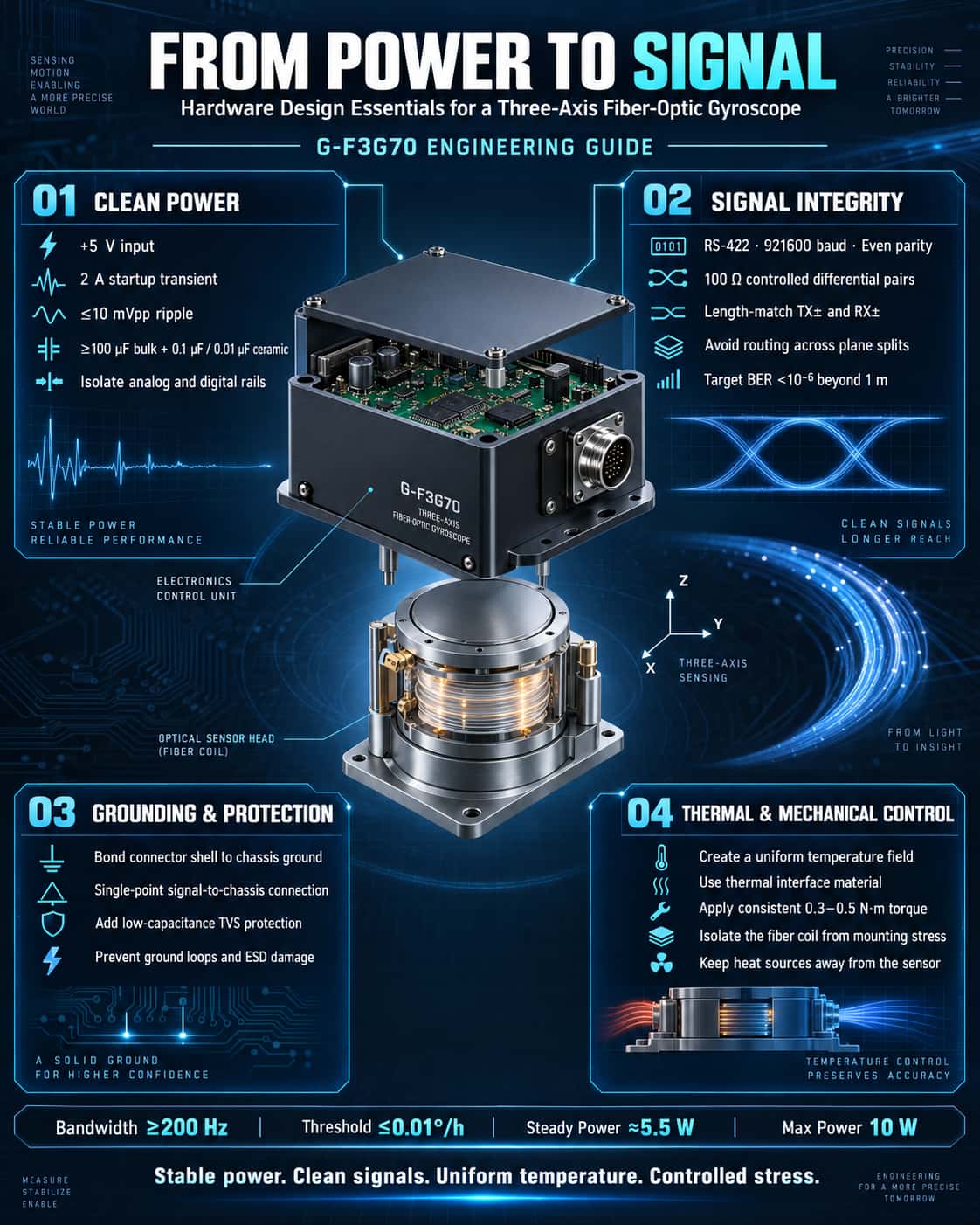
Thanks to advantages such as solid-state construction, rapid startup, wide dynamic range, and high reliability, three-axis fiber-optic gyroscopes (FOGs) play a critical role in small missiles, guided bombs, and high-precision attitude control systems. However, fully realizing their performance potential requires meticulous attention to hardware design—particularly regarding power supply, signal chains, and interface layout. Using the G-F3G70 three-axis FOG as a case study, this article outlines key design considerations from an engineering perspective. 1. Power Supply Design: Low Noise and Transient Response as Primary Considerations A gyroscope's bias stability and angle random walk (ARW) coefficient are directly affected by power supply quality. The G-F3G70 requires a +5V power supply; the instantaneous startup current can reach 2A, while steady-state power consumption is approximately 5.5W (peaking at 10W across the full temperature range). Design efforts should focus on the following: · Low-noise LDOs or post-stage DC-DC filtering: Switching ripple must be controlled to within 10mVpp—especially in the 100Hz to 1MHz frequency range—to prevent coupling into the signal processing chain and degrading the angle random walk performance. · Adequate decoupling capacitance: High-capacity tantalum capacitors (≥100μF) combined with high-frequency ceramic capacitors (0.1μF and 0.01μF in parallel) should be placed at the connector inputs (pins 5 and 13 of the J30-15ZKP). This ensures the system can handle the 2A startup current surge and prevents voltage drops that could trigger resets or data anomalies. · Power and ground plane isolation: A single-point connection—using a ferrite bead or a low-value resistor—is recommended between the digital power supply (interface side) and the analog power supply (internal gyroscope conditioning circuitry). This prevents digital noise from radiating through the power lines and interfering with sensitive optoelectronic detection components. 2. Signal Interface: Differential Transmission and Robust Grounding The G-F3G70 utilizes an RS-422 serial interface with a baud rate of 921,600 and even parity. The data output includes three-axis angular rates (32-bit signed integers) and three temperature readings (16-bit signed integers with 1/16 resolution). Hardware design guidelines: · Strict differential pair length matching: TX+/TX- and RX+/RX- signals must be routed as differential pairs with controlled impedance (typically 100Ω). Avoid routing across split planes to suppress common-mode interference and ensure a bit error rate (BER) of less than 10⁻⁶ for long-distance (>1m) transmission. · Shielding and grounding: The connector housing should be connected to chassis ground (PE), while signal ground (GND) connects to PE at a single point via an RC parallel network (e.g., 10Ω + 0.1μF). This prevents ground loops from introducing power-frequency interference that could compromise bias repeatability (specification: ≤0.03–0.05°/h). · ESD protection: TVS diodes (e.g., SMCJ5.0CA) must be installed on all interface pins (especially R+/R-) to prevent damage to the internal RS-422 driver chips caused by hot-plugging or electrostatic discharge. 3. Mechanical structure and thermal management: Temperature gradients determine bias stability The G-F3G70 exhibits a bias stability of 0.10–0.15°/h under varying temperature conditions (1°C/min), indicating that temperature gradients are the primary source of error. Engineering best practices include: · Thermal conduction at the mounting interface: Both the circuit housing (60×60×24mm) and the sensor head (Φ67×17.5mm) must make tight contact with the mounting structure. Applying thermal grease is recommended to reduce thermal resistance and ensure a uniform temperature field across the unit, thereby preventing localized hot spots from causing refractive index changes in the fiber optic coil. · Stress isolation: Fastening torque for mounting holes (M3×4 and Φ2.7×8) must be consistent (recommended: 0.3–0.5 N·m). Excessive mechanical stress transmitted through the housing to the fiber optic coil can induce birefringence, leading to increased bias drift. The use of flexible washers or O-rings is recommended for stress isolation. 4. Layout and Connector Selection: Defining Signal Flow The pin assignments for the J30-15ZKP connector clearly define the power supply (red/black) and serial port (yellow/orange/blue/green) connections. Key layout considerations include: · High/Low-Voltage Separation: Route the +5V power line (red) and signal lines (yellow/blue) on separate PCB layers or with adequate spacing (≥3W, where W is the trace width) to minimize interference from the power supply's magnetic field on the differential signals. · Temperature Sensor Routing: While the three temperature channels (internal signals output as data) require no external processing, users performing calibration must ensure that no heat sources (such as high-power resistors) directly radiate heat onto the gyroscope body; otherwise, deviations between temperature readings and the actual ambient temperature will compromise the accuracy of the compensation model. In summary, the hardware design of a three-axis fiber-optic gyroscope involves far more than simply connecting power and reading serial data. From power supply transient response and differential signal integrity to thermal management and mechanical stress relief, every aspect is closely linked to core performance metrics such as bias stability, repeatability, and random walk. By adhering to these guidelines and utilizing the detailed specifications from the G-F3G70 manual (e.g., bandwidth ≥200 Hz, threshold ≤0.01°/h), the system can reliably achieve navigation-grade angular rate measurement under actual operating conditions, providing a dependable data foundation for high-dynamic control applications.
Read More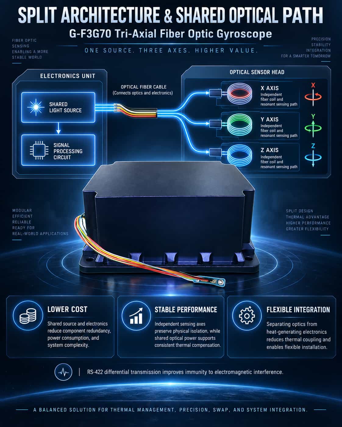
The core technical requirement for a tri-axial fiber optic gyroscope (FOG) is to integrate three sensing axes—measuring angular rates along the X, Y, and Z axes respectively—within the smallest possible volume, while ensuring that the three axes remain independent and free from mutual interference. The G-F3G70 tri-axial FOG employs a technical approach where the light source and signal processing circuitry are shared across all three axes, yet each axis retains its own independent fiber coil and resonant cavity. In simpler terms: while the light source and circuitry are shared, the sensing core for each axis remains independent. The primary advantages of this approach include a reduction in redundant components, lower overall power consumption and cost, and the elimination of cross-interference between three separate sets of circuits. Furthermore, sharing a single light source ensures consistent optical power across all three axes, facilitating unified modeling for temperature compensation algorithms. Split Architecture: Separation of Circuitry and Optics The most distinct structural feature of the G-F3G70 is the separation of the electronics unit and the sensor head, connected by a cable. What is the engineering rationale behind this split design? The core components of a fiber optic gyroscope—such as the light source, detector, modulator, and fiber coil—are optical devices that are extremely sensitive to temperature fluctuations and mechanical stress. In contrast, the electronics section, which handles signal processing, power management, and communication interfaces, generates heat during operation. If optical components and circuitry were tightly packaged within the same housing, heat generated by the electronics would transfer directly to the fiber coil. This would create localized temperature gradients, leading to thermally induced non-reciprocity errors—one of the primary sources of error in fiber optic gyroscopes. The split design physically separates the heat source (electronics) from the sensitive elements (optical components), fundamentally reducing thermal coupling effects. Additionally, the split design offers greater flexibility for system integration. The electronics unit and the sensor head can be mounted in different locations on the host platform: the sensor head can be placed near the platform's center of gravity for precise angular motion sensing, while the electronics unit can be situated in an area with more space or better heat dissipation. Connected by a flexible cable, the two units do not restrict each other's mounting position or orientation. Engineering Trade-offs and Compensation for the Split Design The split design does not come without a cost. When the circuitry is separated from the sensor, the weak signals carried by the cables become susceptible to electromagnetic interference; consequently, the G-F3G70 employs RS-422 differential signaling for external communication, ensuring high common-mode rejection and robust interference immunity. Furthermore, signal pre-amplification and filtering are performed within the sensor head, guaranteeing that the output signal possesses an adequate signal-to-noise ratio. In addition, the split design imposes stricter requirements on installation precision. The mounting surface of the electronics unit and the locating shoulder of the sensor head must be accurately aligned with the carrier's reference datum; any angular misalignment translates directly into non-orthogonality errors between the three axes, thereby compromising north-finding accuracy and navigation solution results. Summary of Design Logic The core design logic behind the G-F3G70’s architecture—featuring a shared optical path for three axes combined with a split-unit structure—can be summarized as follows: ` Shared light source and circuitry across three axes—reduces power consumption, cost, and complexity while ensuring axis-to-axis consistency; ` Independent sensing axes—maintains physical independence of the three-axis sensing function, preventing motion coupling and signal crosstalk; ` Physical separation of optics and electronics—isolates heat sources and protects optical components from thermal and mechanical stresses; ` Split-unit installation for enhanced flexibility—accommodates the spatial constraints of various carriers and simplifies system integration. Overall, this design is not merely for aesthetics but addresses two fundamental contradictions in the engineering of fiber-optic gyroscopes: the trade-off between thermal management and accuracy, and the conflict between component size and installation flexibility. By adopting a split-unit architecture as an optimal engineering compromise, the G-F3G70 delivers medium-to-high precision performance while meeting the comprehensive requirements for size, weight, power consumption, and reliability demanded by tactical-grade navigation and guidance systems.
Read More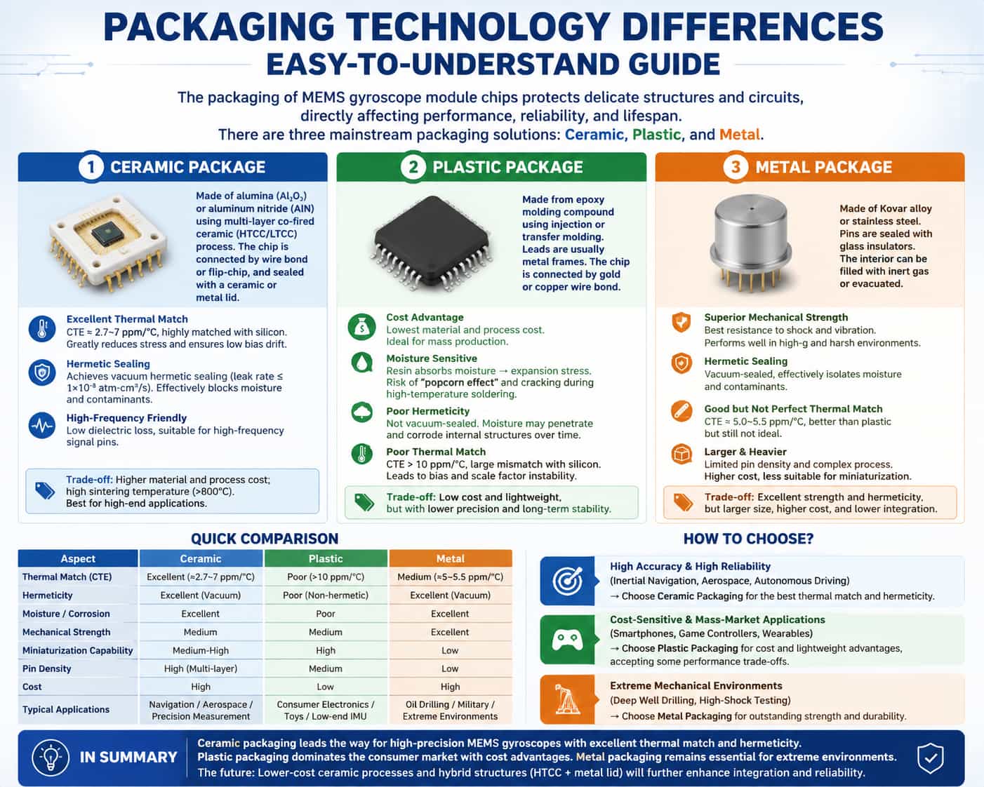
The packaging of MEMS gyroscope module chips refers to the complete process—carried out after wafer-level fabrication of the sensing structure and signal processing circuitry—of enclosing the singulated chip, routing out leads, and establishing electrical interconnections. Packaging directly impacts the module's thermo-mechanical stress environment, hermetic reliability, and signal integrity. Currently, the mainstream packaging solutions for these chips fall into three categories: ceramic, plastic, and metal packaging. Comparison of the Three Packaging Solutions (1) Ceramic Packaging Alumina or aluminum nitride serves as the substrate and housing material. A multi-layer co-fired ceramic process (HTCC/LTCC) is used to fabricate the cavity and interconnect layers; the chip is connected to internal pads via wire bonding or flip-chip bonding and finally sealed with a ceramic or metal lid. Thermal Matching: The Coefficient of Thermal Expansion (CTE) is approximately 6.0–7.2 ppm/°C for alumina and 2.7 ppm/°C for aluminum nitride. These values align closely with silicon, significantly reducing stress exerted on the MEMS structure during temperature fluctuations and ensuring low zero-bias drift. Hermeticity: Capable of achieving a true hermetic seal (leak rate ≤ 1×10⁻⁸ atm·cm³/s), effectively isolating moisture and contaminants, and offering excellent long-term reliability. High Frequency/Low Parasitics: Ceramic materials exhibit low dielectric loss, making them suitable for high-frequency signal pins. The limitations of ceramic packaging include high material and processing costs and high sintering temperatures (>800°C); it is primarily suited for high-end applications. (2) Plastic Packaging The housing is formed using epoxy resin molding compounds via injection or transfer molding processes. Metal lead frames are typically used for pins, and connections between the chip and pins are made via gold or copper wire bonding. Plastic packaging offers significant cost advantages; material and processing costs are substantially lower than those of ceramic or metal packaging, making it suitable for mass production. The disadvantages of plastic packaging are primarily threefold. The CTE of the resin generally exceeds 10 ppm/°C, resulting in significant thermal mismatch with the silicon chip; thermal stress directly causes fluctuations in zero-bias and scale factor. The hydrophilicity of epoxy resin causes swelling stress upon moisture absorption; during high-temperature soldering, this can trigger the "popcorn effect," leading to package cracking. Furthermore, moisture penetration gradually corrodes internal structures, compromising long-term reliability. Additionally, insufficient hermeticity prevents vacuum sealing, making it difficult to meet the long-term stability requirements of high-precision applications. (3) Metal Packaging These packages utilize a housing made of Kovar alloy (an iron-nickel-cobalt alloy) or stainless steel. Leads are insulated and sealed against the metal shell using glass insulators, and the interior can be filled with inert gas or evacuated to a vacuum. Metal packaging is renowned for its exceptional mechanical strength, offering the best shock and vibration resistance among all packaging solutions; it is capable of withstanding extreme operating environments characterized by high overload and high-impact forces. Moreover, its hermeticity rivals that of ceramic packaging, effectively blocking moisture and contaminants to ensure the long-term reliability of the internal chip. The coefficient of thermal expansion (CTE) for metal packaging is approximately 5.0–5.5 ppm/°C; while superior to that of plastic packaging, a mismatch with the silicon die remains, meaning the impact of thermal stress cannot be ignored. Additionally, the package's relatively large size and weight, combined with limited lead density, hinder the development of miniaturized and highly integrated modules. The manufacturing process is complex, and the overall cost can even exceed that of ceramic packaging. Coupled with the industry-wide trend toward miniaturization, metal packaging is gradually being replaced by ceramic packaging solutions in the field of MEMS gyroscopes. Comparative Summary Table Comparison Criteria Ceramic packaging Plastic packaging Metal package Thermal Compatibility (CTE) Excellent (≈2.7–7 ppm/°C) Poor (>10 ppm/°C) Medium (≈5–5.5 ppm/°C) Hermeticity Excellent (vacuum-tight) Poor (non-hermetic) Excellent (vacuum-tight) Moisture/Corrosion Resistance Excellent Poor Excellent Mechanical Strength Medium Medium Excellent Miniaturization Capability Medium-high High Low Lead Density High (supports multi-layer routing) Medium Low Cost High Low High Typical Applications Navigation/Aerospace/Precision measurement Consumer electronics/toys/low-end IMUs Oil drilling / Military / Extreme environments Selection Recommendations · High-precision, high-reliability sectors (inertial navigation, aerospace, autonomous driving): Ceramic packaging is the optimal choice, offering excellent thermal matching and hermeticity. · Consumer electronics and cost-sensitive applications (mobile phones, game controllers, wearable devices): Plastic packaging offers advantages in cost and weight reduction, though it entails some trade-offs in precision. · Extreme mechanical environments (deep-well drilling, high-impact testing): Metal packaging retains a niche market due to its superior mechanical strength. In summary, ceramic packaging—leveraging the dual advantages of thermal matching and hermeticity—represents the mainstream technological approach for high-precision MEMS gyroscope module chips; plastic packaging dominates the consumer market through cost-efficiency; and metal packaging is relegated to specialized environments. Future trends point toward continuous cost reduction in ceramic packaging processes and an evolution toward composite structures—combining high-temperature co-fired ceramics (HTCC) with metal lids—to further enhance integration and reliability, thereby solidifying its core position in high-value applications.
Read More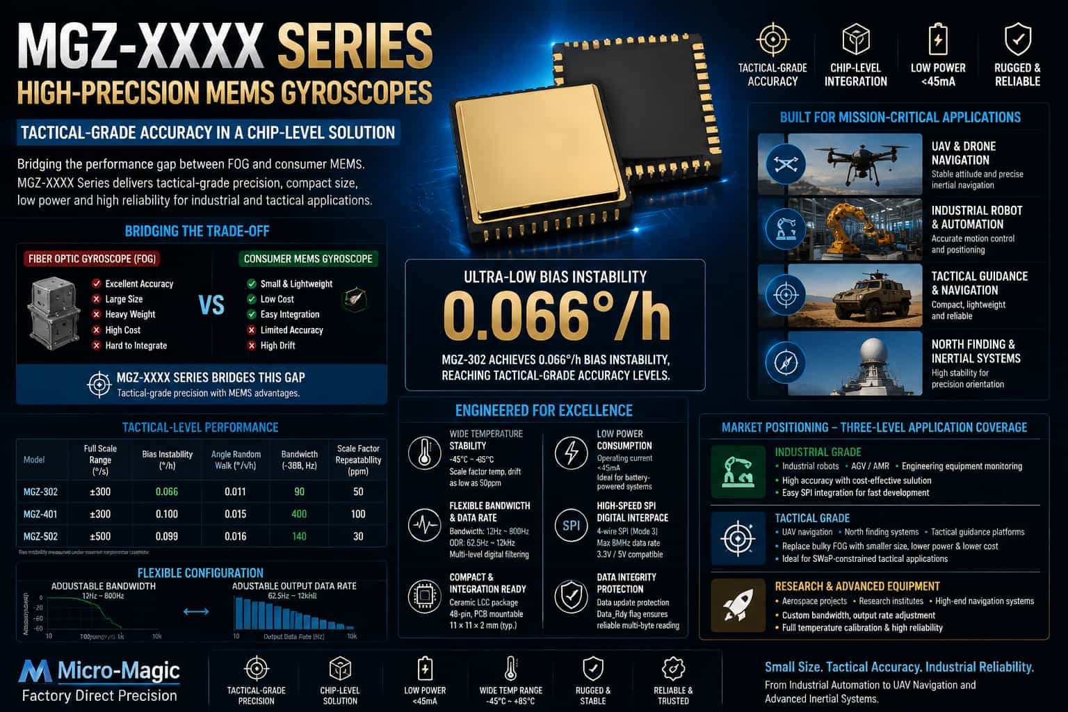
When selecting inertial sensors, engineers often face a dilemma: while fiber-optic gyroscopes meet accuracy requirements, they are bulky, heavy (often weighing hundreds of grams), and expensive (starting at tens of thousands of yuan), making them difficult to integrate into compact platforms like drones and robots. Conversely, while consumer-grade MEMS gyroscopes offer suitable size and cost, their bias stability—typically ranging from several to dozens of degrees per hour—leads to rapid error accumulation in industrial-grade attitude control or tactical-grade navigation scenarios, failing to meet performance standards. Underlying this choice is a long-standing performance gap between these two technological approaches: high-precision solutions are cumbersome and costly, whereas lightweight options lack sufficient accuracy, and there has long been a lack of a chip-level solution capable of effectively balancing both requirements. The MGZ-XXXX series of high-precision MEMS single-axis gyroscope chips was designed specifically to bridge this gap. 1. Product Positioning: Chip-level, Tactical-grade Precision The MGZ-XXXX series is clearly positioned to provide a chip-level solution—suitable for direct integration onto circuit boards—for projects requiring tactical or industrial-grade precision but unable to accommodate the size and cost of fiber-optic gyroscopes. By utilizing high-performance MEMS oscillating structures and low-noise signal chain designs, this series pushes key performance metrics to the threshold of tactical-grade applications. Taking representative models such as the MGZ-302 and MGZ-502 as examples: model Measuring range (°/s) Bias instability (°/h) Angular random walk (°/√h) bandwidth (-3dB, Hz) Scale factor repeatability (ppm) MGZ-302 ±300 0.066 0.011 90 50 MGZ-401 0.1 0.015 400 100 MGZ-502 ±500 0.099 0.016 140 30 Bias instability is a key parameter measuring the magnitude of output drift in a gyroscope under constant temperature conditions. The MGZ-302 achieves a bias instability of 0.066°/h, firmly placing it within the tactical-grade precision range and matching or exceeding the performance of leading international competitors. The MGZ-401 further extends the bandwidth to 400 Hz and reduces group delay to 1.1 ms, enabling the capture of rapid attitude changes in high-frequency dynamic response scenarios. At the same time, this series retains the inherent core advantages of MEMS technology: · Size: Ceramic LCC package with 48 pins, suitable for direct PCB surface mounting. · Power Consumption: Normal operating current <45 mA, making it ideal for battery-powered devices. · Interface: Standard 4-wire SPI digital output (Mode 3 timing) with read/write speeds up to 8 MHz. 2. Core Technical Advantages: From Specifications to Engineering Implementation 2.1. Performance Assurance Across the Full Temperature Range Temperature drift is a primary source of error in the engineering application of MEMS gyroscopes. The MGZ-XXXX series features an integrated 16-bit temperature sensor (register addresses 0x30–0x31) and utilizes factory-calibrated temperature compensation parameters to maintain scale factor stability across a wide temperature range. High-end models achieve scale factor temperature drift as low as 50 ppm, meaning that output scale variations remain within 0.05% across the -45°C to +85°C temperature range. 2.2. Flexible Bandwidth and Filter Configuration Developers can flexibly adjust the output bandwidth (12 Hz–800 Hz) and data refresh rate (62.5 Hz–12 kHz) via registers 0x6F (LPF_BW_CTRL) and 0x6E (ODR). The chip incorporates a configurable three-stage low-pass filter, allowing developers to balance "low latency" against "low noise" based on application requirements—for instance, enabling a single-stage filter minimizes latency, while enabling a three-stage filter minimizes noise. This design enables a single chip to support applications ranging from low-speed attitude monitoring (such as tower tilt detection) to high-speed flight control (such as FPV racing drones). 2.3. Hardware Integration Friendliness and Data Integrity Protection The datasheet provides comprehensive reference circuit designs, PCB layout guidelines, and recommendations for decoupling capacitor selection. The chip supports adaptive 3.3V/5V interface voltage levels and specifies clear power-up sequencing requirements for VCC and VIO, offering substantial benefits in shortening product development cycles and mitigating migration risks. It features a built-in data update protection mechanism: sensor data is first written to a DSP buffer and only refreshed after the old data in the SPI registers has been read. Additionally, a Data_Rdy flag prevents frame misalignment during read operations, ensuring the integrity of multi-byte data transfers. 3. Market Positioning: Adaptation to Three-Stage Application Scenarios Based on accuracy grades and application scenarios, the market positioning of the MGZ-XXXX series is categorized into three tiers: 3.1. Industrial-Grade Applications: Balancing Accuracy and Cost Targeting applications such as industrial robots, AGVs/AMRs, and attitude monitoring for construction machinery, models like the MGZ-201 and MGZ-301 offer bias stability of 0.02–0.03°/h. Their SPI digital output interfaces facilitate direct integration with mainstream MCUs and DSPs. Industry statistics indicate that the demand for high-performance inertial sensors in the fields of industrial automation and intelligent equipment monitoring is growing at an average annual rate of 12%. 3.2. Tactical-Grade Applications: A Key Arena for Precision Replacement of Fiber-Optic Gyroscopes The accuracy specifications of models such as the MGZ-302 and MGZ-401 enable them to cover application scenarios previously dominated by fiber-optic gyroscopes. In tactical-grade applications—such as UAV navigation, missile guidance, and north-finding instruments—where strict constraints exist regarding Size, Weight, and Power (SWaP), MEMS gyroscopes are progressively replacing traditional fiber-optic gyroscopes. The MGZ series stands out as a strong contender for domestic substitution solutions, thanks to its compact ceramic packaging (typical dimensions: 11×11×2 mm), full-temperature-range calibration capabilities, and military-grade reliability screening standards. 3.3. Scientific Research and High-End Equipment: Demands for Customization and High Reliability Catering to university laboratories, research institutes, and aerospace and defense projects, the MGZ series supports customized bandwidth configurations, adjustable output rates, and parameter calibration across the full temperature range, enabling adaptation to the specific requirements of diverse projects. As the market penetration of domestically produced high-precision MEMS inertial sensors continues to rise within the mid-to-high-end sectors, demand in this market segment is growing rapidly.
Read More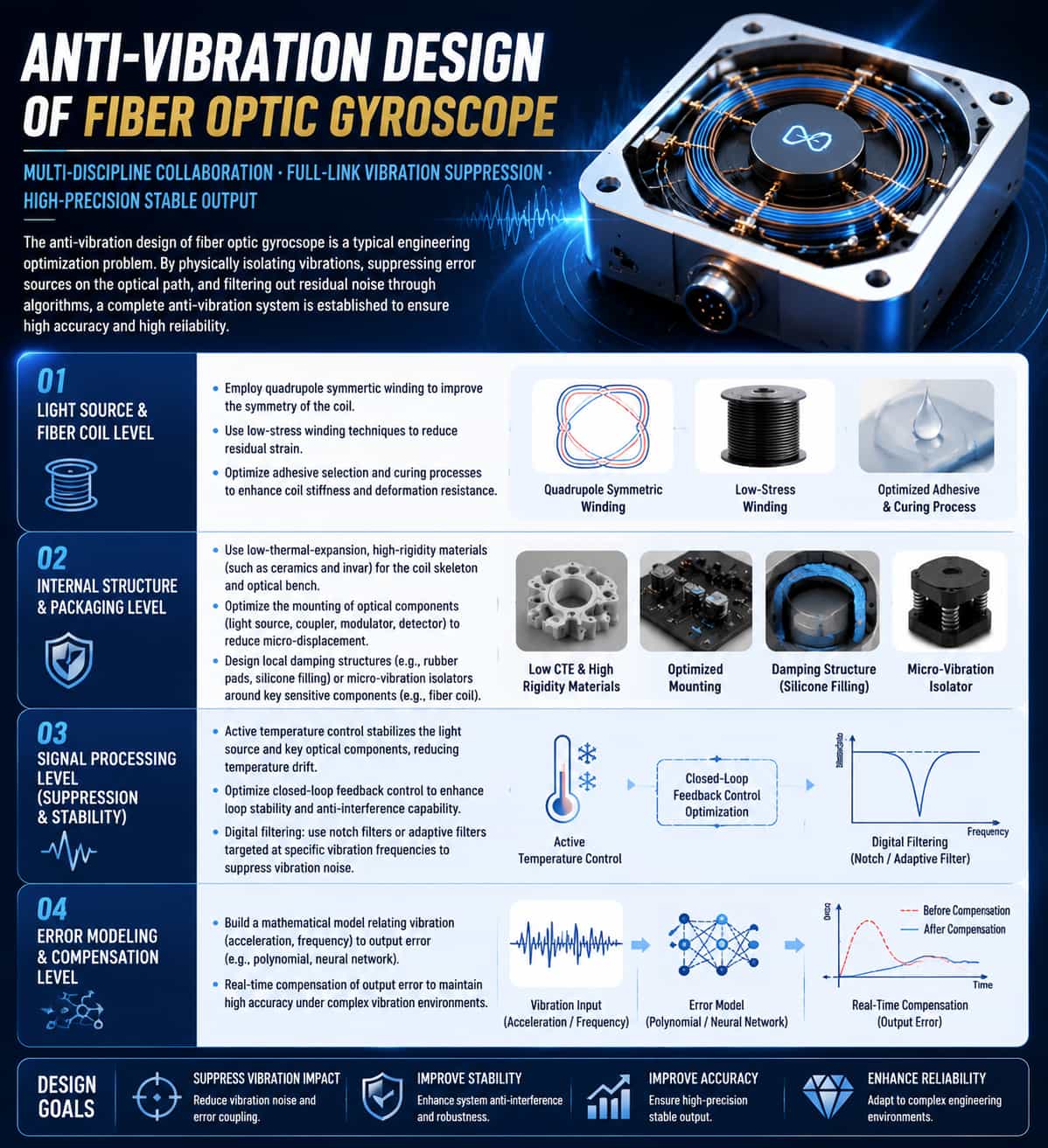
The anti-vibration design of fiber optic gyroscope is a typical engineering optimization problem that requires collaborative efforts in mechanical structure, optical path design, and signal processing. The current mainstream solution is to physically isolate vibrations, suppress error sources on the optical path, and filter out residual noise through algorithms, thus forming a complete anti-vibration system. At the light source and fiber coil level, the design of the fiber coil is optimized by employing quadrupole symmetric winding, low-stress winding techniques, and optimizing adhesive selection and curing processes to enhance the coil's stiffness and resistance to deformation. At the internal structure design and packaging level, materials with low thermal expansion coefficients and high rigidity (such as ceramics and invar) are used to fabricate the coil skeleton and optical bench, and the mounting methods of optical components (light source, coupler, modulator, detector) are optimized to reduce micro-displacement. Simultaneously, local damping structures (such as rubber pads, silicone filling) or micro-vibration isolators are designed around key sensitive internal components of the gyroscope (such as the fiber coil). At the signal processing level, active temperature control is used to stabilize the temperature of the light source and key optical components, thereby reducing temperature drift. Closed-loop feedback control is optimized to enhance the stability and anti-interference capability of the control loop. Digital filtering techniques, such as notch filters or adaptive filters designed for specific vibration frequencies, are employed to suppress vibration noise during signal processing. Additionally, through error modeling and compensation, a mathematical model (e.g., polynomial, neural network) relating vibration (acceleration, frequency) to output error is established to enable real-time compensation in the output.
Read More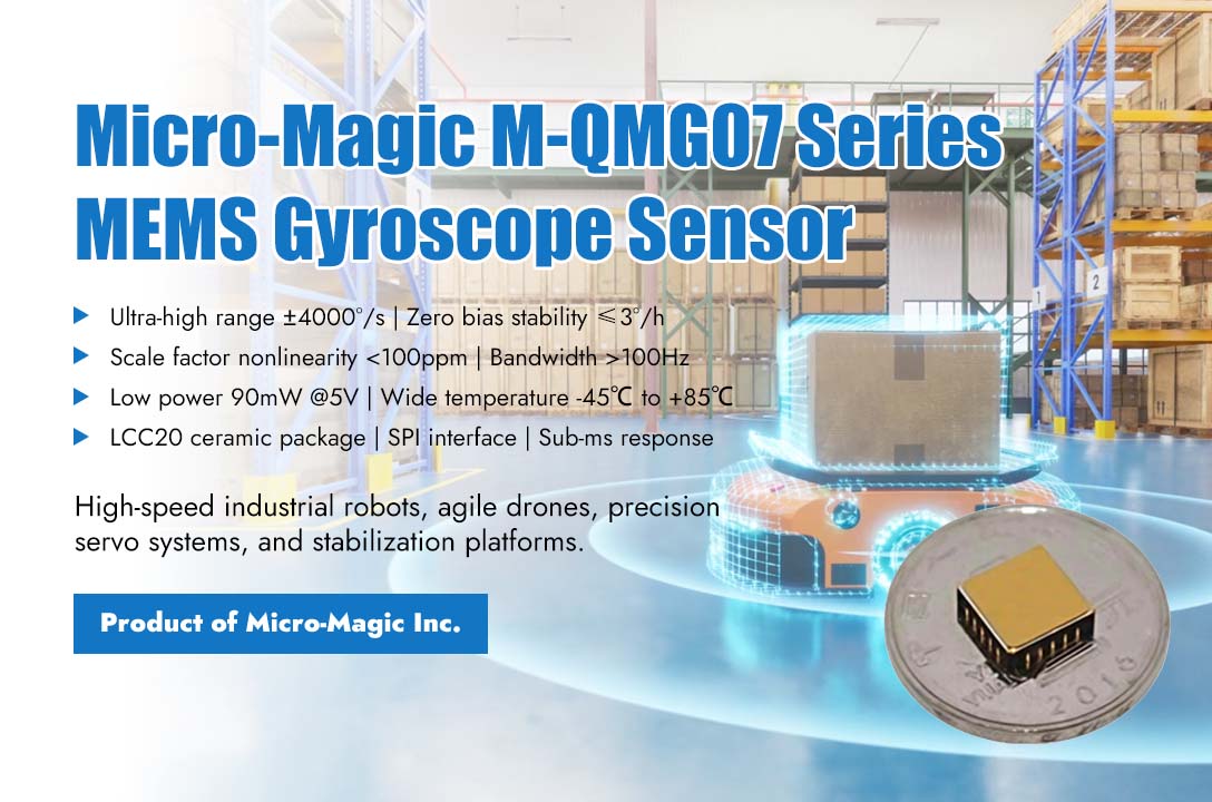
Amid the rapid development in industrial automation, drone, and robotic control, systems have imposed unprecedented stringent requirements on motion sensing devices. Traditional gyroscopes often face technical bottlenecks such as insufficient range, reduced accuracy, and delayed response in ultra-high-speed and high-dynamic motion scenarios, becoming a critical factor limiting the performance breakthrough of high-end equipment. Recently, Micro-Magic officially launched the M-QMG07 series single-axis MEMS gyroscope. With its ultra-large dynamic range of up to ±4000°/s and exceptional bias stability of ≤3°/h, it has opened a new technical landscape for high-speed, high-precision motion control. The core breakthrough of the M-QMG07 series lies in its integration of an extremely wide range coverage with military-grade measurement accuracy. This series offers multiple range options from ±500°/s to ±4000°/s, enabling comprehensive capture of angular motion across the full spectrum—from micro-oscillations in precision instruments to intense maneuvers of high-speed aircraft. Crucially, while achieving such an ultra-wide range, it maintains industry-leading precision metrics: zero bias stability of better than 3°/h at room temperature, a scale factor nonlinearity below 100ppm, and outstanding performance across the full temperature range, ensuring stable and reliable data output even under complex thermal and vibration conditions. This series of gyroscope sensors has brought revolutionary improvements to applications such as high-speed industrial robots, high-end servo systems, highly maneuverable drones, and precision stabilization platforms. For example, when high-speed parallel robots perform sorting and packaging tasks, the joint acceleration of the robotic arm is extremely high, and traditional gyroscopes are prone to signal truncation due to range limitations, which can lead to control oscillations and even instability. The ultra large range of M-QMG07 can respond to instantaneous angular velocity changes of up to thousands of degrees per second without distortion, providing a real and continuous data foundation for real-time motion planning and vibration suppression. At the same time, its high zero bias stability significantly reduces attitude drift during long-term operation, helping to achieve higher repeat positioning accuracy and job consistency. In the field of drones, whether it is the extreme yaw of racing models on bends or the rapid stabilization of industry drones in strong turbulence, extreme requirements are placed on the range and dynamic response of gyroscopes. The M-QMG07 can not only fully capture instantaneous angular velocities of ±4000°/s, but its bandwidth can be configured to be above 100Hz, with sub-millisecond response capability, ensuring that the flight control system can perceive and compensate for every high-frequency disturbance in real time, greatly improving flight stability, control accuracy, and resistance to environmental interference. To achieve such outstanding performance, M-QMG07 adopts a full silicon MEMS capacitive sensing structure and customized low-power signal processing ASIC, with a typical power consumption of no more than 90mW under a 5V power supply. The product adopts a sturdy LCC20 ceramic package, with excellent resistance to mechanical shock and vibration characteristics, and supports wide temperature operation from -45℃ to +85℃. Through the standard SPI interface and programmable filters, users can flexibly configure data output modes and bandwidth, achieving system level noise optimization and dynamic performance adjustment. At present, the M-QMG07 series can provide engineering samples and comprehensive technical support. With the gradual introduction of this chip in multiple fields, the technological boundaries of high-speed motion control are expected to be further expanded, empowering the next generation of intelligent systems to achieve more agile, precise, and stable motion performance.
Read More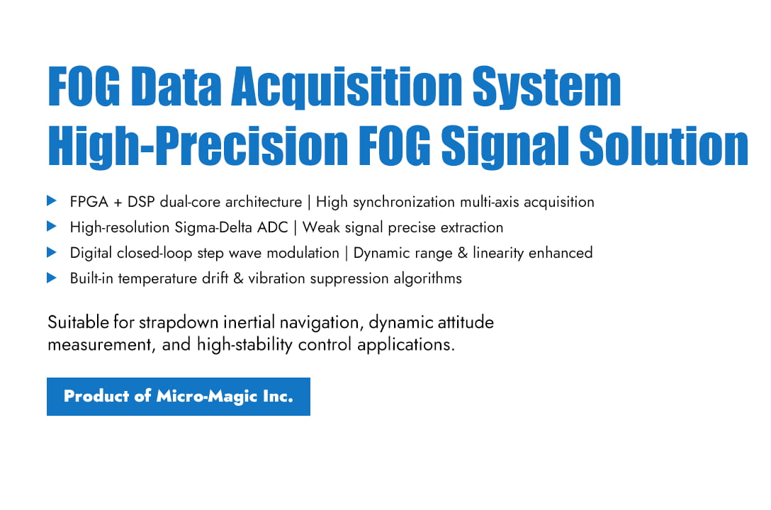
The design of the fiber optic gyroscope data acquisition system focuses on how to extract weak angular velocity signals from noise and achieve high-precision, high-synchronization digital conversion. The current mainstream technical approach adopts the "FPGA+DSP" architecture to meet the requirements of front-end high-speed data acquisition and back-end complex signal processing. The overall system architecture typically consists of four layers: sensor front-end, signal conditioning and acquisition, core data processing, and communication and power management. For a triaxial integrated system, it is necessary to synchronize the acquisition of signals from three orthogonal directions. In terms of hardware design, the front end uses a precision signal conditioning circuit (amplification, level shifting) to match the ADC input range. A high-resolution Sigma-Delta ADC is selected to ensure accurate weak signal acquisition. An FPGA is responsible for multi-axis synchronous triggering and digital demodulation, while a DSP performs closed-loop control, error compensation, and strapdown inertial navigation algorithm. The communication interfaces support RS-422, CAN, etc., and include a PPS (pulse per second) synchronization function. In terms of software algorithms, a digital closed-loop step wave modulation technique is adopted, where feedback phase is applied via a Y-waveguide to significantly improve dynamic range and linearity. Meanwhile, algorithms such as dynamic voltage compensation, vibration suppression, and reference channel noise reduction are integrated to effectively eliminate temperature drift and light source intensity noise. The data processing flow includes initialization calibration, synchronous sampling, computation compensation, and integral output, and the final data is packaged according to the communication protocol and transmitted to the host computer. The system design balances high precision, high synchronization, and strong anti-interference ability, making it suitable for navigation application scenarios that require strict dynamic response and stability.
Read More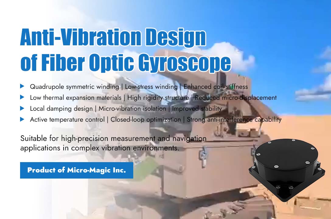
The anti-vibration design of fiber optic gyroscope is a typical engineering optimization problem that requires collaborative efforts in mechanical structure, optical path design, and signal processing. The current mainstream solution is to physically isolate vibrations, suppress error sources on the optical path, and filter out residual noise through algorithms, thus forming a complete anti-vibration system. At the light source and fiber coil level, the design of the fiber coil is optimized by employing quadrupole symmetric winding, low-stress winding techniques, and optimizing adhesive selection and curing processes to enhance the coil's stiffness and resistance to deformation. At the internal structure design and packaging level, materials with low thermal expansion coefficients and high rigidity (such as ceramics and invar) are used to fabricate the coil skeleton and optical bench, and the mounting methods of optical components (light source, coupler, modulator, detector) are optimized to reduce micro-displacement. Simultaneously, local damping structures (such as rubber pads, silicone filling) or micro-vibration isolators are designed around key sensitive internal components of the gyroscope (such as the fiber coil). At the signal processing level, active temperature control is used to stabilize the temperature of the light source and key optical components, thereby reducing temperature drift. Closed-loop feedback control is optimized to enhance the stability and anti-interference capability of the control loop. Digital filtering techniques, such as notch filters or adaptive filters designed for specific vibration frequencies, are employed to suppress vibration noise during signal processing. Additionally, through error modeling and compensation, a mathematical model (e.g., polynomial, neural network) relating vibration (acceleration, frequency) to output error is established to enable real-time compensation in the output.
Read More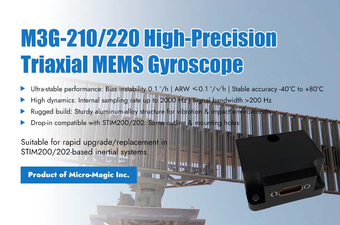
In the field of precision inertial measurement, technological innovation and system compatibility are emerging as dual engines driving industry advancement. Recently, Micro-Magic Inc launched M3G-210/220 high-precision triaxial MEMS gyroscope, with its outstanding technical performance and highly compatible design philosophy, fully matches Sensonor's STIM200/202, offering new solutions for industrial and research applications. The M3G-210/220 gyroscope exhibits significant advantages in technical performance, with zero bias instability reaching the level of 0.1 °/h, angle random walk controlled within 0.1 °/√ h, and stable measurement accuracy maintained within the working temperature range of -40℃ to +80℃. The product adopts a sturdy aluminum alloy structure design, which can adapt to complex working environments such as vibration and impact. The internal sampling rate can reach up to 2000Hz, and the signal bandwidth exceeds 200Hz, which can accurately capture rapid dynamic changes. It is worth noting that M3G-210/220 fully considers the convenience of system integration in its design. Its mechanical dimensions and interface design are fully compatible with the widely used STIM200/202 solution in the industry, including the same external specifications, matching mounting hole positions, and standardized 15 pin Micro-D connector layout. This physical compatibility enables existing systems to upgrade or replace equipment without undergoing mechanical modifications. In terms of communication protocols, the product offers multiple working modes, among which the specially optimized STIMGYRO-90 mode can achieve complete integration with the STIM200/202 system in terms of data format, instruction set, and working status. At the same time, the product also supports multiple custom communication protocols, providing users with flexible system integration options. The device retains professional functions such as external trigger input and time synchronization signal output, and has a complete system self-monitoring and status reporting mechanism. From a technical architecture perspective, the M3G-210/220 embodies a new approach to sensor design, while improving core performance indicators, it fully respects the existing technological ecosystem and reduces system integration barriers through compatibility design. This design concept enables the product to quickly integrate into various inertial measurement systems, from precision optical stabilization platforms to motion control devices, from scientific research experimental equipment to industrial detection systems, demonstrating a wide range of application potential. The balance between technological innovation and system compatibility is an important direction for the development of high-end measuring equipment. The practice of M3G-210/220 in this regard shows that through careful design, performance improvement and system adaptation can be organically unified. With the deepening application of measurement technology in various fields, this solution that combines excellent performance and good compatibility will bring more choices for system integrators and end users. At present, the product has begun to provide services to users in key areas, and its performance in practical applications deserves further attention. Under the development trend of emphasizing both technological progress and system compatibility, the launch of such products provides new possibilities for the expansion of inertial measurement technology applications.
Read More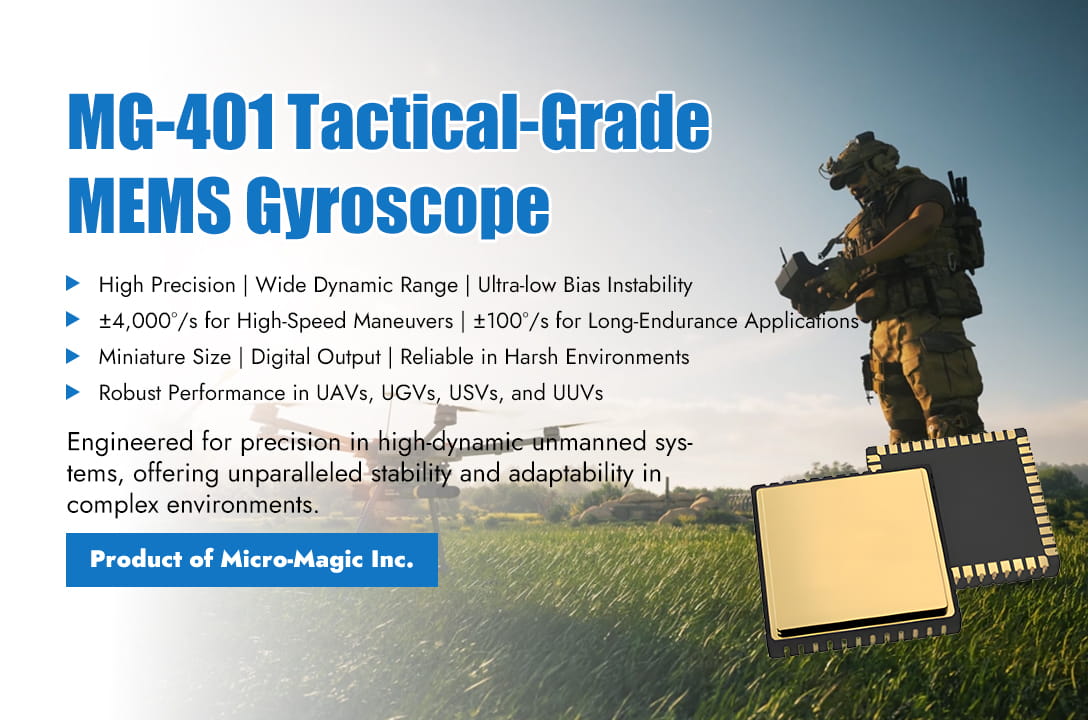
At a pivotal stage in the global advancement of unmanned systems toward intelligence, swarm capabilities, and high precision, the performance of core sensors has become a critical bottleneck limiting system capability enhancement. Recently, Micro-Magic, a leading designer and manufacturer of inertial sensors, officially launched a new generation of tactical-grade single-axis MEMS gyroscope sensor series. This product line, optimized for deep integration with UAVs, UGVs, USVs, UUVs, and various robotic platforms, aims to provide a robust and precise motion sensing foundation for next-generation high-dynamic, highly autonomous unmanned systems, enabling stable operation and intelligent decision-making in complex environments The newly released chip series covers multiple models, including the MG-101/102, MG-401 series, MG-501 series, MG-2001, and MG-4001/4002. Featuring a unified miniaturized ceramic package (10×10×3.5 mm, weighing 1.5 grams) and fully digital output, it delivers a comprehensive solution ranging from ultra-high precision to ultra-wide dynamic range. Its technical specifications directly address the stringent requirements of unmanned systems across diverse scenarios: whether it's the extreme maneuvers of racing drones with up to ±4,000°/s, the stable measurement of minute angular velocities within ±100°/s for underwater submersibles over tens of hours, or the reliable and precise angular rate data provided by the series in rugged terrains against continuous impacts and vibrations for unmanned vehicles. At a pivotal stage in the global advancement of unmanned systems toward intelligence, swarm capabilities, and high precision, the performance of core sensors has become a critical bottleneck limiting system capability enhancement. Recently, Micro-Magic, a leading designer and manufacturer of inertial sensors, officially launched a new generation of tactical-grade single-axis MEMS gyroscope sensor series. This product line, optimized for deep integration with UAVs, UGVs, USVs, UUVs, and various robotic platforms, aims to provide a robust and precise motion sensing foundation for next-generation high-dynamic, highly autonomous unmanned systems, enabling stable operation and intelligent decision-making in complex environments The newly released chip series covers multiple models, including the MG-101/102, MG-401 series, MG-501 series, MG-2001, and MG-4001/4002. Featuring a unified miniaturized ceramic package (10×10×3.5 mm, weighing 1.5 grams) and fully digital output, it delivers a comprehensive solution ranging from ultra-high precision to ultra-wide dynamic range. Its technical specifications directly address the stringent requirements of unmanned systems across diverse scenarios: whether it's the extreme maneuvers of racing drones with up to ±4,000°/s, the stable measurement of minute angular velocities within ±100°/s for underwater submersibles over tens of hours, or the reliable and precise angular rate data provided by the series in rugged terrains against continuous impacts and vibrations for unmanned vehicles. MG401 M-QMG07 M3G-220
Read Moreleave a message
Scan to Wechat :
