




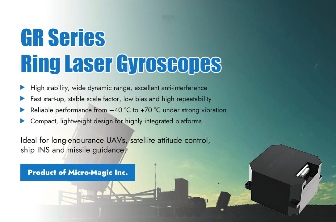
Recently, Micro-Magic Inc, a provider of inertial technology solutions, officially released its new generation of Ring Laser Gyroscope series products. As a new masterpiece for strategic navigation and high-precision inertial measurement applications, the launch of this series of products marks another major breakthrough for the company in the field of high-precision and high reliability inertial sensing, aiming to meet the increasing demand for strategic navigation performance in aerospace, defense technology, high-end industry and other fields. The GR series RLG products integrate advanced laser optical technology and mature temperature control processes, with high stability, wide dynamic range, and excellent anti-interference performance. It has advantages such as fast start-up and stable proportional factor, and can maintain stable output even in extreme temperatures (-40℃ to +70℃) and strong vibration environments. Not only does it meet the strict requirements of traditional inertial navigation systems for accuracy and reliability, but it also provides reliable angular motion perception capability for the new generation of high dynamic platforms. In strategic navigation applications such as long endurance unmanned aerial vehicles, satellite attitude control, ship inertial navigation systems, and missile guidance, the GR series RLG products, with their low zero bias error and high repeatability, can effectively improve the autonomous navigation and attitude control accuracy of the system in complex environments. Meanwhile, its compact structural design and lightweight body make it highly suitable for high integration platforms with limited space. The GR series launched four products (G-R30, G-R50, G-R70, G-R90) based on different performance indicators to meet customers' needs for different application scenarios. The technical director of Micro-Magic stated, “The GR series RLG is not just a product, It is our response, stemming from a profound understanding of customer challenges in strategic applications. We firmly believe that with its excellent precision, strong environmental adaptability, and outstanding reliability, the GR series products will become one of the most trusted core components for our partners in promoting innovation in high-end navigation and autonomous systems”.
Read More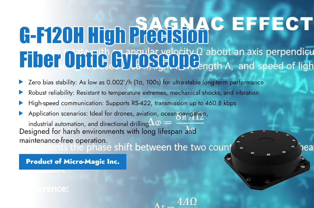
Quick preview of article content In the field of modern navigation technology, accuracy and reliability are crucial requirements. Both military defense systems, aerospace vehicles, ocean ships and autonomous vehicle need highly accurate navigation solutions. Among numerous navigation sensors, Fiber Optic Gyroscope (FOG) has become the core component of precision navigation systems due to its unique advantages. Fiber optic gyroscope consists of a laser light source, fiber optic coil, coupler, and photodetector, and its working principle is based on the Sagnac effect. The laser is divided into two beams and propagates in the fiber coil in clockwise and counterclockwise directions, respectively. When the system is stationary, two beams of light return simultaneously and interfere destructively; When the system rotates, two beams of light will produce a phase difference, and by detecting this phase difference, the rotational angular velocity can be accurately measured. Technical Characteristics of Fiber Optic Gyroscope 1. High precision and high stability: Fiber optic gyroscopes do not have mechanical rotating components, avoiding the wear and drift problems of traditional mechanical gyroscopes, and have extremely high measurement accuracy and long-term stability. The drift of modern high-precision FOG can reach below 0.001/h. 2. Quick response Due to the use of optical measurement principles, fiber optic gyroscopes have extremely fast response speeds and can detect instantaneous angle changes in real time, which is crucial for precise control of high-speed moving objects. 3. Strong anti-interference ability Fiber optic gyroscopes have strong resistance to electromagnetic interference, vibration, and impact, making them suitable for working in harsh environments such as aerospace, military, and other applications. 4. Long lifespan and maintenance free The design without moving parts gives the fiber optic gyroscope an extremely long service life, usually up to 10 years or more, and requires minimal maintenance, greatly reducing the cost of use. 5. Wide dynamic range Modern fiber optic gyroscopes are capable of measuring angular velocities ranging from 0.001°/h to 1000 °/s, covering a wide range of measurement needs from extremely low to ultra-high speeds. The Main Application Areas of Fiber Optic Gyroscope 1. Aerospace Field Fiber optic gyroscope is a core component in navigation and guidance systems for aircraft, spacecraft, and other aircraft, used to accurately measure the attitude, angular velocity, and heading of the aircraft, ensuring flight safety and precise navigation. In the attitude control system of satellites, rockets and other spacecraft, fiber optic gyroscopes are used for attitude stabilization, orientation and control to ensure the stable attitude of the spacecraft in space. In rocket launch scenarios, it is used for tracking and measuring the rocket's launch trajectory to ensure accurate launch. 2. Military Field In missile guidance, fiber optic gyroscope is an important component of the missile guidance system, used to provide accurate attitude and direction information, ensuring the accuracy of missile hits. On military vehicles such as tanks and armored vehicles, fiber optic gyroscopes are used to provide attitude and direction information for navigation, control, and artillery aiming. In submarine navigation, the inertial navigation system used for submarines provides accurate position and attitude information. 3. Other Application Areas Fiber optic gyroscope can be used for ship navigation, providing accurate heading, attitude, and angular velocity information for ship navigation and control. In fields such as oil exploration and mineral exploration, fiber optic gyroscopes are used to measure the inclination and displacement of the ground, for geological exploration and drilling guidance. For example, in directional drilling operations, fiber optic gyroscopes are used to measure the precise orientation and inclination angle of drill bits, helping to achieve complex wellbore trajectory control. In the field of industrial automation, fiber optic gyroscopes are used for attitude control and motion tracking of robots, positioning and control of precision instruments, etc. The Development of Fiber Optic Gyroscope 1. Integration and Miniaturization With the development of micro optics and integrated optics technology, fiber optic gyroscopes are moving towards smaller size and lower power consumption, making them applicable to more portable and embedded systems. As a leading inertial sensor design and manufacturer in China, Micro-Magic Inc has developed a series of integrated fiber optic gyroscope products (G-F50,G-F70, G-F80, G-F98, G-F120) to meet various customer needs. 2. Multi Axis Integration The traditional single axis FOG is evolving into a two axis, three-axis integrated IMU (Inertial Measurement Unit), providing a more complete solution for measuring motion information. Micro-Magic Inc provides G-F2X70, G-F2X64 series two axis fiber optic gyroscope products and G-F3X35, G-F3G70, G-F3G90, G-F3X112 series three-axis fiber optic gyroscope products. 3. Performance Improvement By improving fiber optic materials, optimizing optical design, and adopting digital signal processing technology, the accuracy and stability of modern fiber optic gyroscopes continue to improve. Taking the G-F120H high-precision fiber optic gyroscope produced by Micro-Magic Inc as an example, advanced integrated optical technology and FPGA closed-loop circuit design have been adopted to achieve higher accuracy, noise control, and efficiency than similar technologies. The zero bias stability is as low as 0.002 °/h (1σ, 100s), and the random walk coefficient is ≤ 0.001 °/√hr. Conclusion Fiber optic gyroscope, as the core sensor of modern precise navigation, plays an irreplaceable role in key fields such as military, aerospace, marine, and autonomous driving due to its high precision, high reliability, and strong anti-interference ability. With the continuous advancement of technology, fiber optic gyroscopes are developing towards higher performance, smaller size, and lower cost, and their application scope will further expand. In future intelligent and autonomous navigation systems, fiber optic gyroscopes will continue to maintain their core position, providing precise directional guidance for human exploration and movement.
Read More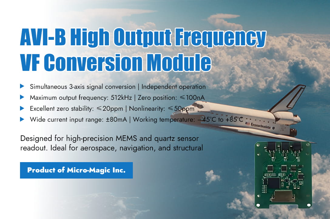
One minute to read the key points of the article Application of Current Frequency Conversion Module in Inertial Sensor System The charge-integration I/F module plays a crucial role in inertial sensor (especially capacitive MEMS inertial sensor) measurement systems, particularly in applications demanding high precision, low noise, and wide dynamic range. Its core value lies in directly and high fidelity converting the weak charge signal output by the sensor into a digital frequency signal. The following introduces the typical applications and advantages of the charge integrator I/F module in inertial sensor systems: Capacitive MEMS Accelerometer/Gyroscope Signal Readout The charge integrator I/F module is used to detect small capacitance changes in the output signals of MEMS inertial sensors (accelerometers, gyroscopes). It directly measures charge and is extremely sensitive to charge changes at the fC (flying coulomb) level, capable of detecting extremely small inertial forces. The integration process itself is a low-pass filter, which can effectively suppress high-frequency noise. Using frequency signals as output, it is insensitive to amplitude noise and interference on the transmission path, making it suitable for long-distance transmission or use in noisy environments. High Precision/Force Balanced(Servo/Force-Feedback) Inertial Sensor In the highest precision inertial sensors, such as navigation grade MEMS or quartz beam accelerometers, a force balance closed-loop working mode is commonly adopted. The detected small displacement (sensed through capacitance/charge changes) is converted into feedback force, which is applied back to the mass block to keep it near zero. In this design process, the I/F module plays a dual role as the driver source for front-end detection and feedback DAC. Achieved ultra-high precision, stability, and precise force control. At the same time, it simplifies the closed-loop control architecture, enabling the entire closed-loop system to be efficiently implemented in the charge/frequency/digital domain. Typical Application Scenarios l High precision navigation and positioning: high-precision inertial navigation systems and inertial measurement units for aviation, aerospace (satellites, rockets), ships, and land vehicles. The requirements for zero bias stability, noise, and scale factor linearity are extremely high. l Earthquake monitoring and geophysical exploration require the measurement of extremely weak ground vibrations (as low as μg acceleration), with strict requirements for low-frequency noise and dynamic range. l Industrial automation and robotics: precision motion control, platform stability, vibration monitoring. l Structural health monitoring: detection of small deformations and vibrations in large buildings, bridges, and dams. l Automotive electronics: advanced driving assistance systems, high-performance MEMS IMUs required for autonomous driving. I/F Conversion Module Products As an inertial sensor designer and manufacturer, Micro-Magic Inc has designed and manufactured a series of high-precision inertial sensor products, such as quartz flexible accelerometers, fiber optic gyroscopes, IMUs, INS, North Seeker, and inclinometers. At the same time, AVI series charge integration I/F (V/F) module products have also been developed in conjunction with it. AVI-F AVI-E AVI-B Performance Index Specification AVI-F AVI-E AVI-B Unit Maximum output frequency 256 512 512 kHz Zero position F0 10 20 100 nA Zero stability 5 5 10 ppm Scale factor temperature coefficient 1 0.5 1 ppm/℃ Scale factor asymmetry 10 30 30 ppm Scale factor comprehensive nonlinearity 15 30 30 ppm Small signal error 0.2 0.5 0.5 Hz Conclusion The charge integrator I/F module is one of the key technologies for achieving high-performance and high-precision signal readout of capacitive inertial sensors, especially MEMS accelerometers and gyroscopes. It is an essential core component in advanced inertial measurement applications that require extremely low noise, ultra-high linearity, wide dynamic range, and digital closed-loop control, providing a critical signal chain solution for high-end inertial sensors at the navigation, tactical, and even some industrial levels. With the advancement of MEMS technology and readout circuit technology, readout schemes based on charge integration principle continue to play an important role in the field of high-performance inertial sensors. AVI-B AVI-E AVI-F
Read More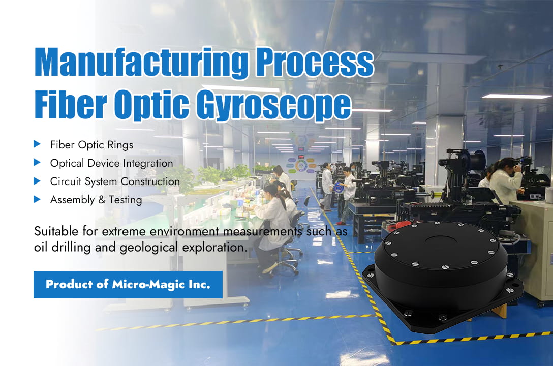
Fiber optic gyroscope has become the preferred core component for high-precision and high reliability inertial navigation systems due to its significant advantages such as all solid state design, no moving parts, fast start-up, long lifespan, wide dynamic range, and strong resistance to impact and vibration. However, behind the outstanding performance of fiber optic gyroscopes is their extremely precise and complex manufacturing process. From the selection and processing of specialized optical fibers, the coupling and alignment of precision optical components, to the precision winding and curing of the core sensing coil, and further to the integration of complex electronic systems and the implementation of sophisticated environmental compensation algorithms – each production stage embodies the crystallization of cutting-edge materials science, precision optical engineering, microelectronics technology, and advanced control theory. Even the slightest deviation during the manufacturing process can have a decisive impact on the accuracy, stability, and reliability of the final product. Below is a detailed introduction to the production process of fiber optic gyroscope. 1. Manufacturing of fiber optic rings The core component of a fiber optic gyroscope is the fiber ring, and its manufacturing process is crucial. Firstly, high-quality optical fibers need to be selected and wound into a ring shape through precise winding processes. During this process, it is necessary to strictly control the tension of the optical fibers, the diameter and density of the winding ring to ensure the performance and stability of the fiber ring. After winding, adhesive coating and curing are performed for shape fixation. Subsequently, the fiber optic ring needs to undergo temperature cycling aging to eliminate internal residual stress and enhance mechanical stability through epoxy coating. 2. Optical Device Integration After the fiber optic ring is manufactured, it needs to be precisely assembled with other optical components. Mainly includes the assembly of Y-waveguide modulators and the integration of light sources and detectors to ensure smooth and stable optical paths. In addition, strict performance testing of the assembled components is required to ensure that they meet the design requirements. 3. Circuit system construction The construction of circuit systems includes the design of signal processing circuits and closed-loop feedback circuits. FPGA serves as the core processor to generate square wave/sawtooth wave modulation signals to drive the Y waveguide, bias the operating point to the sensitive area, and calculate the phase difference (Δφ) of the interference signal output by the detector, which is converted into angular velocity (Ω). Dynamically compensate for Sagnac phase difference through digital closed-loop control to improve linearity and dynamic range. 4. Whole machine assembly and testing After completing the manufacturing of fiber optic rings, optical components, and circuit boards, the next step is to proceed with overall assembly. This process includes environmental adaptability encapsulation and performance calibration and compensation. The optical and electronic units are sealed inside a metal shielding shell to isolate temperature and humidity changes and electromagnetic interference. Military grade products use titanium alloy shells to enhance impact resistance. Subsequently, a series of tests and calibrations were conducted on the fiber optic gyroscope, including zero bias calibration, temperature compensation, and threshold testing, to ensure that all performance indicators meet the expected requirements. The key process difficulties in the manufacturing process of fiber optic gyroscopes mainly include the following: 1. Precision winding of fiber optic coils The stress generated during the winding process of fiber optic coils can cause polarization errors. The solution is to use polarization maintaining fibers and adopt a symmetrical winding process. 2. Packaging and Interconnection of Integrated Optical Chips (Y-Waveguides) Y-Waveguides are the core multifunctional integrated optical devices of FOGs. During the packaging and interconnection process, the alignment accuracy of the optical axis is extremely high. the solution to this difficulty is to use an active alignment system and a polarization maintaining fusion splicer. 3. Temperature drift Temperature changes can cause gyroscope phase drift, affecting measurement accuracy. The solution is to use multi-stage depolarizers and adopt segmented temperature compensation algorithms to eliminate the impact of temperature drift.
Read More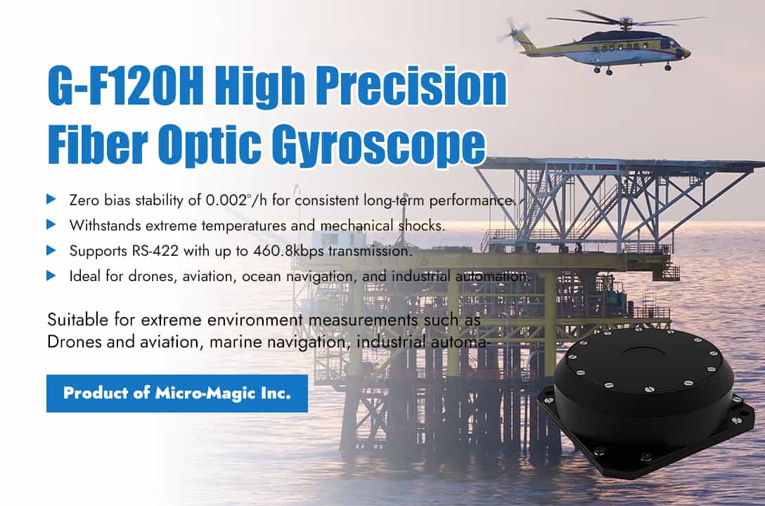
Quickly get the product information in one minute In the rapidly changing technological era, precise inertial navigation technology has become a core requirement in fields such as autonomous driving, aerospace, and ocean exploration. The G-F120H high-precision fiber optic gyroscope launched by Micro Magic Inc, with its outstanding performance and reliability, provides stable and accurate navigation solutions for global users, empowering industries to ascend to new heights of intelligence. The G-F120H high-precision fiber optic gyroscope has become a leader in navigation grade applications through the integrated design of optical and electronic components. Taking into account the weight and size of the product, it exhibits excellent inertial performance. By adopting advanced integrated optical technology and FPGA closed-loop electronic circuits, G-F120H achieves better accuracy, noise control, and efficiency than similar technologies. In addition, the internal calibration function of the product further optimizes the thermal suppression effect, while the separation design between electronic devices and FOG sensitive ring components ensures wide environmental adaptability. Core advantage: Breaking through technological boundaries 1. Ultimate precision, steadfast reliability Zero bias stability is as low as 0.002 °/h (1σ, 100s), ensuring high consistency of attitude measurement during long-term operation. Full temperature zero bias repeatability ≤0.05°/h, operating in extreme environments (-40℃ to +65℃) with always-on performance. Random walk coefficient ≤0.001°/√ hr, effectively suppressing noise interference and resulting in purer data output. 2. Rugged durability, fearlessly conquering challenges. Through rigorous mechanical testing, ensure the accuracy and reliability of product operation in complex environments. Random vibration (20Hz~500Hz, each axis vibrates for 15 minutes), the absolute value of the zero-bias value during vibration and the average zero bias value before and after vibration is less than 0.05 °/h. 30g mechanical impact (half sine wave, 10ms), the zero-position change value before and after impact is less than 0.02°/h, ensuring the reliability of high dynamic scenarios such as onboard and airborne. 3. High speed communication, seamless integration Supports RS-422 bidirectional serial communication, with a transmission rate of up to 460.8kbps and strong compatibility. The data frame contains 32-bit valid gyroscope data and 14-bit temperature data, combined with parity check to ensure the integrity and real-time transmission of information. Application scenarios empower diverse fields (1) Drones and Aviation: Provide sub-degree accuracy (0.05°) for onboard heading and attitude systems to ensure flight safety and stability. (2) Ocean navigation: The ideal choice for marine gyrocompasses, with anti-magnetic interference (magnetic field sensitivity ≤ 0.02°/h/Gs) and adaptability to complex marine environments. (3) Industrial automation: precise positioning (1cm accuracy) and speed measurement (0.03m/s accuracy), empowering high-precision motion control for AGVs, robots, and others. Quality assurance: defined by technical standards The G-F120H series strictly follows international technical specifications and offers three models, G-F120H-A/B/C, to meet the accuracy requirements of different scenarios: (1) G-F120H-C: Flagship model with optimal zero bias stability and full temperature repeatability, suitable for aerospace grade high-precision missions. (2) G-F120H-B: Balancing performance and cost, suitable for mid to high end markets such as automotive and marine applications. (3) G-F120H-A: Economical choice, performance still exceeds industry benchmarks, covering industrial automation needs. Choose Micro Magic, Unlock a Precision-Driven Future As a leading global provider of inertial navigation solutions, Micro Magic Inc is driven by innovation and continues to push the limits of technology. The G-F120H fiber optic gyroscope is not only a device, but also a reliable partner for you to move towards the era of intelligence. G-F120 Whatever you needs, Micro-Magic is at your side. --
Read More
Fiber optic gyroscope is based on Sagna effect and is widely used for measuring angular velocity in navigation and attitude control. Key indicators typically include zero bias stability, scaling factor, random walk, bandwidth, noise, temperature characteristics, and so on. By measuring these indicators, the performance of fiber optic gyroscopes can be comprehensively evaluated, and system design and compensation algorithms can be optimized based on these data. 1. Zero Bias Series Testing 1.1 Bias Definition: The average equivalent angular velocity output of a fiber optic gyroscope when there is no angular velocity input. Test Equipment: horizontal reference device, fiber optic gyroscope output measurement recording device. Test method: Fix the fiber optic gyroscope on a horizontal reference, with the input axis (IRA) pointing in the east-west direction. Record output data for at least 1 hour after power on, with a sampling frequency that meets the Nyquist criterion (≥ 2 times the highest frequency of the signal). Calculation formula: Where K is the scaling factor, is the average output value. 1.2 Bias Stability Definition: The degree of dispersion of zero bias output around the mean reflects short-term stability. Test method: Same as bias test, but requires long-term data recording (at least 1 hour). Calculation formula: where: : Zero bias stability, measured in degrees per hour (° ⁄ h) : The single-sided amplitude output of the fiber optic gyroscope at time . 1.3 Bias Repeatability Definition: Perform multiple power tests to ensure consistency of zero bias. Test method: Repeat the zero-bias test for more than 6 times, with power off and cooling to room temperature at intervals between each test. Calculation formula: For each test data, process it according to formula (1), calculate the zero bias, and then calculate the zero-bias repeatability of Q tests according to the following formula. Where, : Zero bias of the i-th test; : Zero bias 1.4 Bias Temperature Sensitivity Definition: Zero bias drift caused by temperature changes. Test method: Set different temperature points (covering the working temperature range) inside the temperature control box, and maintain a constant temperature for 30 minutes at each temperature point. Measure the zero bias at each temperature point and calculate the deviation from the room temperature zero bias. Calculation formula: The test data is processed according to formula (1), and the zero bias of the fiber optic gyroscope at room temperature and each test temperature point is calculated separately. The zero bias temperature sensitivity of the fiber optic gyroscope is calculated according to the following formula: :The i-th test temperature. :room temperature 2. Scale Factor Series Testing 2.1 Scale Factor Definition: Linear proportional relationship between output signal and input angular velocity Test equipment: high-precision rate turntable (error<1/3 of the tested gyroscope index) Test method: Select ≥ 11 angular velocity points (including the maximum input angular velocity) uniformly in both forward and reverse directions. Record the mean output of each point and fit a straight line using the least squares method. Calculation formula: Let be the average output of the fiber optic gyroscope at the jth input angular velocity, and the scaling factor calculation method is as follows: The linear model for establishing the input-output relationship of fiber optic gyroscope is as follows: Using the least squares method to calculate K, Where ∅ is the rotational speed of the speed turntable, measured in degrees per second (° ⁄ s) 2.2 Scale factor nonlinearity Definition: Output the maximum deviation relative to the fitted line. Calculation formula: According to the above method, the input-output relationship of the fiber optic gyroscope is represented by fitting a straight line as follows: Calculate the point-by-point nonlinear deviation of the output characteristics of the fiber optic gyroscope according to the following formula: Calculate the scaling factor linearity according to the following formula, and create the nonlinear deviation curve of the fiber optic gyroscope output (the horizontal axis represents the input angular velocity, and the vertical axis represents the nonlinear deviation) 2.3 Scale factor temperature sensitivity Test method: Test the scaling factor at different temperature points and calculate the deviation caused by temperature changes. Calculation formula: The test data is processed according to the calculation method of scale factor, and the scale factor of the fiber optic gyroscope at room temperature and each test temperature point is calculated separately. The temperature sensitivity of the scale factor is calculated according to the following formula: 3. Random Walk Coefficient (RWC) Definition: Integral angular velocity error caused by white noise output. Test method: Short time (tens of seconds) high-frequency sampling, analyze Allan variance. Formula for calculating Allan variance: a) There are n initial sample data of fiber optic gyroscope output values obtained at the initial sampling interval time . According to the calculation formula for gyroscope zero bias, the output angular velocity of each fiber optic gyroscope output value is calculated to obtain the initial sample data of output angular velocity, as shown in the following formula: b) For continuous data of n initial samples, k continuous data are grouped together, and the time length of the array is set to , where τ equals , 2 , Calculate the average value of the array data for each time length. c) Find the average difference between two adjacent arrays: d) Calculate the variance of a set of random variables: …… (17) Repeat the above process with different values of, and obtain a curve in the double logarithmic coordinate system, which is called the Allan variance curve. Using the Allan variance model below, the coefficients are obtained through least squares fitting, and then the random walk coefficient RWC is calculated: Conclusion: The key indicator testing of fiber optic gyroscope is a bridge connecting research and development with practical applications. By quantitatively verifying performance, ensuring reliability, and meeting standard compliance, it ensures its "precision, stability, and usability" in military and civilian high-precision fields, while laying the foundation for technological innovation and cost optimization. GF2X64 Dual-Axis Low Precision Fiber Optic Gyroscope GF-60 Medium and Low Precision Fiber Optic Gyroscope GF3G90 Tri-Axis Fiber Optic Gyroscope
Read More
Fiber optic gyroscopes (FOGs) are highly accurate sensors used to measure angular velocity. They are widely used in fields such as aviation, navigation, and seismic research due to their high precision, sensitivity, and excellent stability. Its core accuracy indicators, including zero bias drift, random walk, and angle measurement error, are the key to evaluating its performance. Detailed explanation of core accuracy indicators Fiber optic gyroscope uses optical fibers as sensing elements to achieve accurate measurement of rotational angular velocity. Its accuracy performance can be comprehensively evaluated through the following three indicators: (1) Bias Stability (Drift Rate) This indicator reflects the output accuracy of the gyroscope in a non rotating state, usually measured by a benchmark accuracy. The zero bias drift of fiber optic gyroscope is extremely low, generally not exceeding 0.2 °/h, ensuring high measurement accuracy. (2) Random Walk (Angular Random Walk, ARW) This indicator measures the stability of the gyroscope output value over a period of time. typically measured in degrees per square root hour (°/√h). For example, the FOG has an ARW of 0.001°/√h. This means that the noise in the gyroscope's output accumulates at a rate of 0.001 degrees per square root of the operating time. (3) Scale Factor Accuracy The scale factor accuracy indicates how well the gyroscope's output corresponds to the actual angular velocity. It is usually expressed as a percentage error. For example, The FOG has a scale factor accuracy of 10 ppm (parts per million)**. This means that for every degree per second (°/s) of actual rotation, the gyroscope's output may deviate by up to 0.001%. Analysis of Factors Affecting Accuracy The accuracy of fiber optic gyroscopes is influenced by various external factors: (1) Temperature: The sensitive components of fiber optic gyroscopes are sensitive to changes in ambient temperature, which may lead to zero bias drift or increased angle measurement errors. (2) Vibration: Environmental vibrations can have adverse effects on the accuracy of fiber optic gyroscopes, potentially leading to unstable output values. (3) Light source: Changes in parameters such as power and wavelength of the light source may also affect the output value of the fiber optic gyroscope, thereby affecting its accuracy. Example of G-F3G70 manufactured by Micro-Magic the G-F3G70 fiber optic gyroscope inertial group is designed for medium and high precision application backgrounds. It adopts three-axis common technology and split design, with low cost and stable performance. The structure adopts optical path and circuit integrated packaging, with simple structure and easy installation. It can be used in navigation guidance, attitude measurement and control systems of small missiles and guided bombs. Main performance index of the fiber-optic gyroscope G-F3G70-A G-F3G70-B G-F3G70-C Unit zero bias stability ≤0.050 (10s) ≤0.03 (10s ) ≤0.02 (10s) (°)/h Zero bias stability full temperature (1℃/min, 100s ) ≤0.15 ≤0.12 ≤0.10 (°)/h Zero bias repeatability ≤0.050 ≤0.03 ≤0.03 (°)/h Random walk coefficient ≤0.002 ≤0.002 ≤0.001 (º)/h1/2 Scale factor nonlinearity ≤20 ppm Scale factor asymmetry ≤20 ppm Scale factor repeatability ≤20 ppm Conclusion With its high precision advantage, fiber optic gyroscopes have been widely used in fields such as aviation, navigation, and earthquake research. For example, in aircraft, fiber optic gyroscopes can accurately determine the position, velocity, and attitude of the aircraft, ensuring stable and precise flight direction. In summary, as a high-precision measurement device, the performance of fiber optic gyroscope is affected by various factors, but it still shows great potential and value in various fields of application. G-F3G70 Affordable price Dynamic Range 400 Deg/S Optic Fiber Gyroscopes China Leading Supplier
Read Moreleave a message
Scan to Wechat :
