




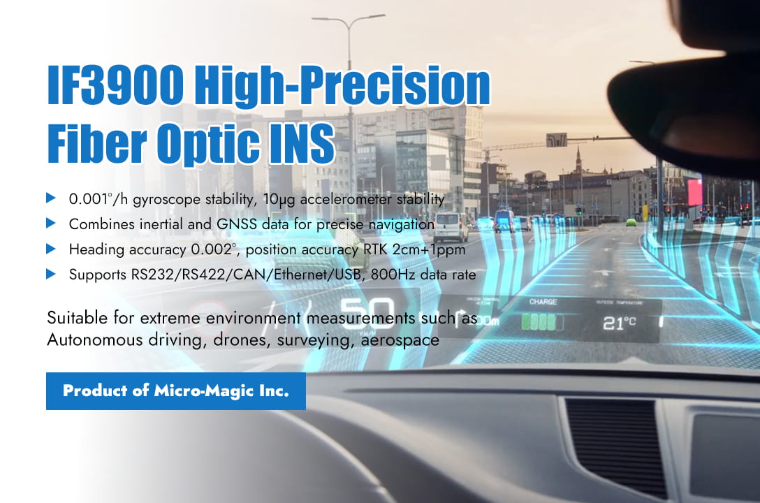
In the complex and ever-changing fields of industry and research, the accuracy and reliability of navigation systems directly determine the success or failure of tasks. The IF3900 series high-precision fiber optic inertial navigation system launched by Micro-Magic Inc., with its groundbreaking technical design and exceptional performance, delivers innovative solutions for premium application scenarios including aerospace, autonomous driving, marine exploration, and UAV navigation. The IF3900 series products are equipped with high-precision closed-loop fiber optic gyroscopes and high-precision quartz accelerometers, and use multi-sensor data fusion technology to combine inertial measurement with GNSS, achieving long-term high-precision integrated navigation. At the same time, IF3900 has post-processing capabilities, which can improve the heading, attitude, and position accuracy of the product through post-processing software. Core Advantage: Perfect Integration of Precision and Reliability 1. Features industry-leading ultra-high precision performance The IF3900 series products are equipped with high-precision closed-loop fiber optic gyroscopes with zero bias stability of 0.001°/h, achieving extremely low drift in all temperature environments to ensure long-term stability of attitude and heading; The built-in high-precision quartz accelerometer has a zero bias stability of up to 10μg, which can accurately sense the motion of the carrier, with no delay in dynamic response, suitable for high-speed and high maneuverability scenarios; At the same time, by integrating multi-sensor fusion technology and combining GNSS with inertial measurement data, even if satellite signals are temporarily lost, centimeter level positioning accuracy can still be maintained through pure inertial navigation. 2. Intelligent post-processing elevates performance to the next level Supporting differential reference stations and post-processing software, the heading accuracy can reach 0.002° (RMS) through algorithm optimization, and the position accuracy can be improved to RTK 2cm+1ppm, meeting the high requirements for data backtracking in scientific surveying, geological exploration, and other fields. 3. Flexible configuration and seamless integration Supports single/dual antenna mode, multi protocol output (RS232/RS422/CAN/Ethernet/USB), with a data update rate of up to 800Hz, compatible with Novatel post-processing software, and easy integration with existing systems. By intelligently compensating for lever arm errors, the offset between GNSS antenna and inertial navigation center can be calibrated with just one click, ensuring data consistency in complex installation scenarios. 4. Strong and durable, Fearless of challenges Through comprehensive vibration testing, covering 20~2000Hz wideband random vibration, multi axis composite sweep frequency, and transient impact (half sine wave 11ms/30g), the overall structural stability and functional integrity of the system under extreme mechanical environments have been verified. Through vibration temperature electromagnetic multiphysics coupling testing, the system is still able to converge quickly, demonstrating its ability to quickly recover under strong disturbance conditions. Application Scenario: Empowering High-End Fields ⚪ Automatic driving and intelligent transportation: provide real-time vehicle attitude, position and speed information to help auto drive system above L4 achieve centimeter level positioning. ⚪ Drones and robots: Maintain stable navigation in indoor or complex terrain without GPS signals, support precise hovering and path planning. ⚪ Surveying and Exploration: The ability for high-precision positioning and continuous navigation ensures the continuity and accuracy of surveying and exploration work ⚪ Aerospace and Defense: precise guidance and attitude control in high dynamic environments to meet military grade reliability requirements. Technical Parameter Highlights ⚪ Attitude accuracy: ≤ 0.002° (RMS), with an error of ≤ 0.005° when maintaining pure inertia for 1 hour. ⚪ Speed accuracy: ≤ 0.02m/s (in combination navigation mode), ≤ 0.1m/s in pure inertia mode. ⚪ Rich interfaces: 4-channel RS422, 1-channel CAN, 1-channel Ethernet, USB, and multi-channel satellite antenna interfaces. ⚪ Power consumption and volume: ≤ 35W power consumption, compact design (190 × 190 × 166mm), weight ≤ 8.5kg, suitable for space limited carriers. IF3900 series product, with its high-precision inertial components, multi-source data fusion capabilities, and flexible post-processing capabilities, has become an ideal choice for reliable navigation in complex environments. Users can fully utilize protocol interfaces for customized development to adapt to diverse application requirements .
Read More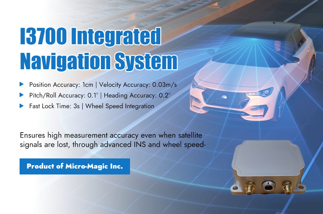
Inertial navigation systems (INS) play a crucial role in autonomous driving technology, especially in addressing the limitations of other sensors such as GPS, cameras, and LiDAR. It provides continuous, high-frequency, and undisturbed motion state information, and is one of the core components of autonomous driving perception and positioning. The Core Function of Inertial Navigation System The core function of inertial navigation system in autonomous driving is the perception of vehicle motion status. Measure the three-dimensional position, velocity, and attitude angle (including roll , pitch, yaw) of the vehicle. The inertial measurement unit (IMU), as the core sensor of INS, has a very high data update frequency (usually above 100Hz), far exceeding GPS (1-10Hz) and camera/LiDAR (10-30Hz), and can capture the instantaneous dynamic changes of the vehicle. 1. Key application scenario: Compensating for other sensor defects Usually in autonomous driving navigation systems, GPS signals are often lost or unreliable, causing GPS signal interruption or severe degradation, such as in tunnels, underground garages, and under elevated bridges where satellite signals are completely blocked; In urban canyons and areas with high-rise buildings, GPS signals are severely reflected and subject to multipath interference, resulting in a significant decrease or even failure in positioning accuracy; Under dense forests, leaves may also block satellite signals. At this point, INS systems typically play an important role. Through dead reckoning, based on the known precise position and attitude at the previous moment, the acceleration and angular velocity measured by IMU are integrated to calculate the current relative displacement and attitude change of the vehicle, thereby calculating the new position and attitude. This ensures the continuity of positioning. By providing high-frequency attitude information, even when the GPS signal is good, the high-frequency, high-precision attitude information (roll, pitch, yaw) provided by INS is difficult for other sensors to provide alone. The following table compares the navigation performance indicators of the I4500 Integrated Navigation System during satellite-assisted navigation versus satellite signal loss scenarios. I4500 System Performance Parameters Index (RMS) Comments Heading Accuracy Dual GNSS 0.1° 2m baseline Single GNSS 0.2° Need to maneuver GNSS failure retention accuracy 0.2°/min Attitude Accuracy GNSS is valid 0.1° GNSS failure retention accuracy 0.2°/min V-G mode (GNSS failure time unlimited, no acceleration) 2° Horizontal Positioning Accuracy GNSS is valid 1.2m Single point 2cm+1ppm RTK GNSS failure (60s) 20m 2. The core hub of multi-sensor fusion The modern auto drive system adopts sensor fusion technology without exception. INS is a key node in the fusion framework. ⚪ By integrating with GNSS, a GNSS/INS integrated navigation system is formed, which is the most classic and mature combination. GNSS provides absolute position and long-term stability, but updates are slow and susceptible to interference; INS provides high-frequency, continuous relative motion information and attitude, but there is cumulative error (drift). The Kalman filter utilizes the advantages of both to mutually correct, GNSS corrects the drift of INS, and INS provides continuous positioning and smooth GNSS output when GNSS fails. Secondly, it can improve overall accuracy and robustness, and the accuracy and reliability of the combined system are much higher than those of individual GNSS or INS. ⚪ By integrating with the speedometer, the speedometer provides wheel speed information (speed, distance traveled), which can assist in correcting INS errors in speed estimation, especially when the vehicle is driving straight. The following table shows the performance indicators of the I3700 integrated navigation system produced by Micro-Magic Inc. Even in the case of satellite signal loss, high measurement accuracy can still be achieved through the algorithm fusion of INS and wheel speedometer. I3700 Navigation Accuracy Indexs Lost Lock Time Navigation Mode Position Accuracy Velocity Accuracy Pitch/Roll Accuracy Heading Accuracy 3s Connect to odometer 1cm 0.03m/s 0.1° 0.2° 10s 1m 0.1m/s 0.1° 0.2° 60s 6m 0.1m/s 0.2° 0.35° ⚪ By integrating with visual/LiDAR SLAM, the high-frequency data of IMU can provide motion prediction for visual or LiDAR processing, reducing the computational complexity of image matching or point cloud matching, and improving real-time performance and robustness (especially in fast motion or weak texture environments). The precise attitude information (roll, pitch) provided by INS is crucial for correctly analyzing the geometric relationships of camera images or LiDAR point clouds on slopes and bumpy roads. Application Cases Taking the I6700 product launched by Micro-Magic Inc as an example, this system can integrate various auxiliary sensors such as GNSS, Odometer, Magnetometer, etc., and provide accurate heading correction function for vehicles in various operating scenarios I6700 Heading Correction Method Function Condition Comments GNSSDual antenna Heading Dual antenna enable Suitable for open fields Kinematic alignment Airplane、Automotive and Marine Suitable for large maneuvering environments, with a carrier speed of at least 3m/s GPSTrue Heading GPS enable Suitable for open fields Acceleration Alignment Helicopter mode Acceleration of at least 2.5m/s2 within 2 seconds Magnetic Heading Magnetic compass enable The magnetic field environment is relatively stable High precision inertial navigation system products launched by Micro-Magic Inc Summary: Inertial Navigation System (INS) is the backbone of autonomous driving positioning system. It provides continuous, high-frequency, and undisturbed vehicle motion status and attitude information, which is a key technology to ensure positioning continuity, robustness, and high-frequency response capability. Especially in challenging scenarios where GPS losing lock (tunnels, urban canyons), INS maintains its positioning capability through dead reckoning, which is an indispensable part of safety redundancy. Although its inherent cumulative error needs to be closely integrated with other sensors (GNSS, wheel speed sensors, vision, LiDAR) for correction, in the multi-sensor fusion framework, INS serves as the core hub, greatly improving the accuracy, reliability, and dynamic performance of the entire positioning system. With the advancement of IMU technology (such as the improvement of MEMS gyroscope accuracy and the miniaturization of solid-state laser gyroscopes) and the optimization of fusion algorithms, the role of INS in autonomous driving will become increasingly important.
Read More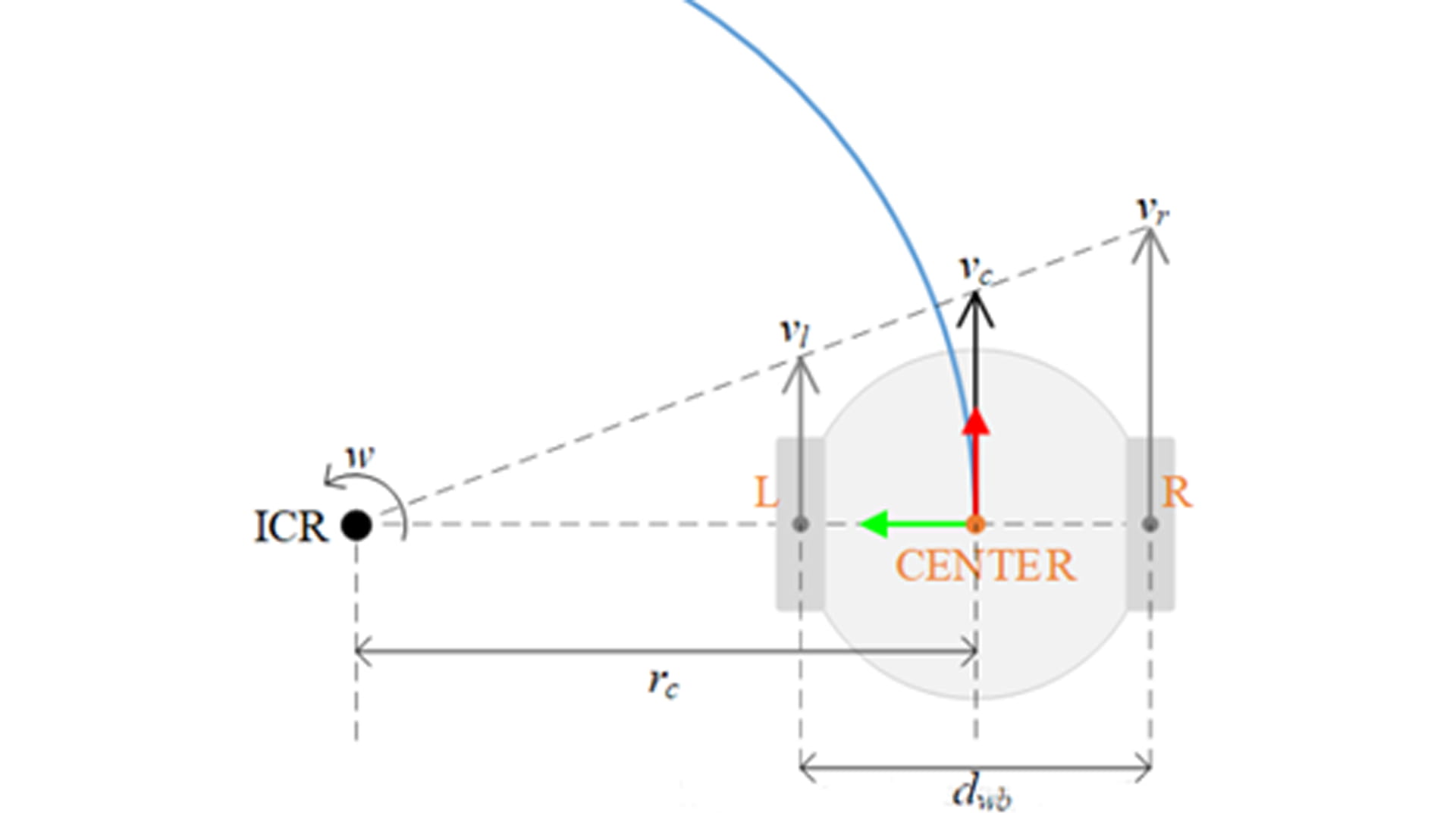
The application of wheel speed sensors in inertial navigation systems (INS) is mainly reflected in multi-sensor fusion and error correction, especially playing an important role in vehicle navigation. Inertial navigation systems (INS) mainly rely on gyroscopes and accelerometers to calculate position, velocity, and attitude through integration, but there is a problem of error accumulation. As a low-cost, high-frequency incremental sensor, the wheel speed sensors can effectively alleviate the problem of error divergence in inertial navigation. At present, in the multi-sensor information fusion system of integrated navigation, the role of the wheel speed sensors is mainly reflected in speed correction and mileage assisted positioning. The wheel speed sensor provides real-time longitudinal velocity, compares it with the acceleration integration result of INS, and fuses the data through Kalman filtering (EKF/UKF) to suppress INS velocity drift. In GPS denied environments (tunnels, underground garages), the wheel speed sensor provides mileage information to assist INS in calculating the relative position of the vehicle, reducing the accumulation of positioning errors. This article indirectly calculates the rate of change in heading angle by analyzing the wheel speed difference of the wheel speed sensor, providing auxiliary correction for vehicle heading navigation. The wheel speed sensors indirectly calculate the rate of change in heading angle (i.e. angular velocity) by measuring the speed difference between the left and right wheels (wheel speed difference), and its core principle is based on the vehicle kinematic model. 1. Basic model assumptions Assuming the vehicle has a rigid body and meets the following conditions: ⚪ Plane motion: The vehicle only moves within a horizontal plane (ignoring pitch and roll). ⚪ No slippage: There is no lateral slippage at the contact point between the tire and the ground (only considering longitudinal rolling). ⚪ Symmetrical wheelbase: The left and right wheelbase (distance between wheels) are fixed values. 2. The mathematical relationship between wheel speed difference and angular velocity The relationship between left and right wheel speed and linear speed is as follows: Left wheel linear velocity Right wheel linear velocity In which: : Left and right wheel speed (radians/second); : Effective rolling radius of tire (assuming constant) According to the instantaneous kinematics analysis of the vehicle, when the vehicle turns, the left and right wheels move around the same instantaneous center of rotation (ICR) (as shown in the figure) The angular velocity of the vehicle (the rate of change in heading angle) . The difference in linear velocity between the left and right wheels is generated by the rotation of the vehicle around the ICR, and the geometric relationship satisfies: , Among them, B is the distance between the left and right wheels (assuming a fixed value); R is the turning radius. Subtracting the two equations yields: Therefore, the rate of change in heading angle (angular velocity) is: 1. Corrections and limitations in practical applications ⚪ Calibration of wheelbase: The actual wheelbase may vary due to load or suspension deformation and needs to be calibrated regularly; The formula assumes that the left and right wheels are symmetrical, and the model needs to be adjusted for asymmetric vehicles. ⚪ Slip and error compensation: During rapid acceleration/braking, the tire slips, causing longitudinal slip and resulting in a wheel speed difference that does not match the true angular velocity. The solution is to introduce IMU angular velocity observations, fuse them through Kalman filtering, or dynamically adjust the slip rate compensation coefficient. ⚪ Tire radius variation: Changes caused by tire pressure, wear, or load variations require indirect calibration through external sensors (such as vision/LiDAR). 2. Example explanation Assuming the parameters of a certain vehicle are as follows: Track width B=1.5m, tire radius r=0.3m Left wheel speed: , Right wheel speed: Calculate the rate of change in heading angle: The vehicle turns left at an angular velocity of 0.4 radians per second. 3. Collaboration with other sensors ⚪ Integration with Inertial Navigation System (INS): The wheel speed sensor provides low-frequency but drift free angular velocity observations, which can correct the accumulated errors of the INS gyroscope. ⚪ Integration with GPS/vision: Long term absolute heading calibration to suppress deviations caused by slip or model errors in the wheel speed sensors. 4. Conclusion The formula for calculating the rate of change of heading angle through wheel speed difference using a wheel speed sensor is: Its advantage lies in strong real-time performance and no cumulative error, but it is limited by slip, tire parameter changes, etc. In practical systems, multi-sensor fusion (such as INS, GPS) is needed to improve robustness.
Read More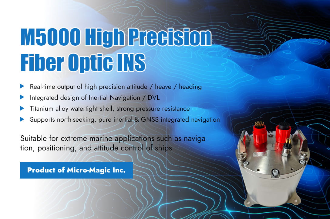
One-minute quick read The Fiber Optical Strapdown Inertial Navigation System (FOG-SINS) uses fiber optic gyroscopes (FOGs) and accelerometers to form a solid-state inertial measurement unit (IMU), which calculates the motion parameters of the carrier in real time through a strapdown algorithm. Due to its significant technological advantages, FOG-SINS has become the core of the new generation of navigation systems in the field of ocean ships. The application of FOG-SINS in the field of ocean ships is mainly reflected in ship navigation, underwater vehicle control, and multi beam measurement. Its core advantages are high precision, high reliability, strong anti-interference ability, autonomous navigation, excellent dynamic performance, and good environmental adaptability. Ship Navigation FOG-SINS can provide continuous and autonomous ship position, heading, attitude (roll, pitch), velocity, and acceleration information for navigation. FOG-SINS is integrated with GNSS (GPS, Beidou, etc.), odometry (Doppler/electromagnetic), compass (magnetic/electric compass), etc. (usually through Kalman filtering) to form a high-precision and high reliability integrated navigation system. FOG SINS provides critical navigation capabilities in the event of GNSS signal interference, obstruction, or failure (such as in canyons, under bridges, electronic warfare environments). FOG-SINS can also provides high-precision attitude reference information for shipborne weapon. The Technical Advantages of FOG-SINS in Ship Navigation : ⚪ High precision and stability: The zero bias stability of modern high-precision FOGs can reach the order of 0.01°/h or even higher, and the angle random walk can reach the order of 0.001°/√h, which can support long-term, high-precision inertial navigation requirements and significantly reduce the accumulation speed of position errors. ⚪ Quick start and response, wide dynamic range: Short start time (much shorter preheating time than mechanical gyroscopes), fast dynamic response, and accurate capture of the ship's rapid maneuvering (such as emergency steering and collision avoidance). Capable of measuring various ship movements from extremely low to high speeds. ⚪ Strong environmental adaptability and resistance to impact and vibration: relatively insensitive to changes in marine environmental factors such as temperature, humidity, and salt spray (especially after good design and compensation), with high reliability. The all solid state structure (without mechanical rotating parts) provides strong immunity to the inherent impacts and vibrations during ship operation, with stable performance and long lifespan. Underwater Vehicle (AUV/UUV) Control FOG SINS, as the core component of the underwater submersible control system, is the core sensor for AUVs to achieve long-term and high-precision autonomous navigation in the absence of GNSS signals underwater. Provide position, attitude, velocity, and acceleration information. The combination of FOG SINS, Doppler log (DVL), depth meter, magnetometer (heading assist), ultra short baseline/long baseline acoustic positioning system (USBL/LBL), gravity/geomagnetic matching navigation, etc., forms an underwater integrated navigation system, greatly improving navigation accuracy and reliability. FOG SINS is the core and foundation of integrated navigation. FOG SINS provides high-precision real-time attitude and heading feedback for the control system of AUVs (such as rudder, thruster, attitude adjustment mechanism), achieving precise depth, height, directional navigation, and complex maneuvers (such as hovering and bottom mounted navigation). Provide a stable attitude reference for task payloads such as sonar (side scan, front view), cameras, and robotic arms to ensure data quality and operational accuracy. The Technical Advantages of FOG SINS in Underwater Submersible Control System : ⚪ Complete autonomy: not relying on external signals, is the key to achieving true autonomous navigation underwater. ⚪ High precision (especially important underwater): High precision attitude and heading information is crucial for underwater obstacle avoidance, terrain tracking, and precise operations. Good zero bias stability can prolong the pure inertial navigation time underwater. ⚪ Anti magnetic field interference: Fiber optic gyroscopes are based on optical principles and are not affected by the complex magnetic field environment underwater (while magnetic compasses are affected). Multi Beam Measurement System The FOG SINS can provide motion compensation for multi beam measurement systems, which is the most core application of FOG SINS in multi beam depth measurement. Accurately measure and compensate in real-time for the attitude changes (roll, pitch, yaw) and heave movements of the measuring vessel/platform at the moment of measurement. FOG SINS can provide accurate heading angle and position information for multi beam measurement system (usually tightly coupled with GNSS), used to determine the precise position and direction of sonar array in the geodetic coordinate system. FOG SINS can provide accurate time reference for the entire measurement system (multibeam sonar, GNSS, motion sensors, sound speed profiler, etc.). The Technical Advantages of FOG SINS in Multi Beam Measurement System: ⚪ Ultra high dynamic performance and bandwidth: capable of accurately and quickly measuring and responding to high-frequency movements of ships/platforms (especially heave and sway caused by short period waves), which is the key to obtaining high-quality seabed terrain data. Its dynamic response capability far exceeds traditional vertical reference units (VRUs). ⚪ High attitude accuracy: The accuracy of attitude (especially roll and pitch) directly affects the compensation accuracy of beam angle. FOG SINS can provide sub angular (<0.01 °) level attitude measurement accuracy, ensuring the accuracy of beam pointing and seabed footprint position calculation. ⚪ Tight integration and time synchronization: FOG SINS are typically designed as highly integrated measurement units (often referred to as POS MV or INS), with internal sensors (gyroscopes, accelerometers) having extremely high synchronization accuracy and the ability to achieve microsecond level time synchronization with other external sensors (GNSS, sonar), ensuring strict alignment of all data in time. Key Products & Technical Specifications Parameter IF3600 IF3700 Pure inertial alignment accuracy North finding accuracy ≤0.1°sec(Φ) ≤0.05°sec(Φ) Attitude accuracy ≤0.008° ≤0.003° Pure inertia retention accuracy Heading angle 0.03°/h ≤0.01° Attitude angle 0.02°/h ≤0.005° Position(CEP50%) ≤1 nmile/h ≤1nmile/h velocity ≤0.5m/s ≤0.5m/s Inertial/satellite combination accuracy Heading ≤0.02° ≤0.02° Attitude ≤0.005° ≤0.005° Position ≤ 2m (单点) ≤ 2cm+1ppm(RTK) ≤1.2m (单点) ≤2cm+1ppm(RTK) Velocity ≤0.02m/s ≤0.02m/s Inertia/ODO/DVL combination accuracy Milemeter/DVL combination 0.25% ×D ≤0.5%×D Conclusion Fiber optic strapdown inertial navigation system has become an indispensable core technology in modern ship high-precision navigation, autonomous operation of underwater vehicles, and high-resolution seabed terrain mapping due to its advantages of all solid state high reliability, dynamic accuracy, and multi-sensor fusion capability. M5000 M1000
Read More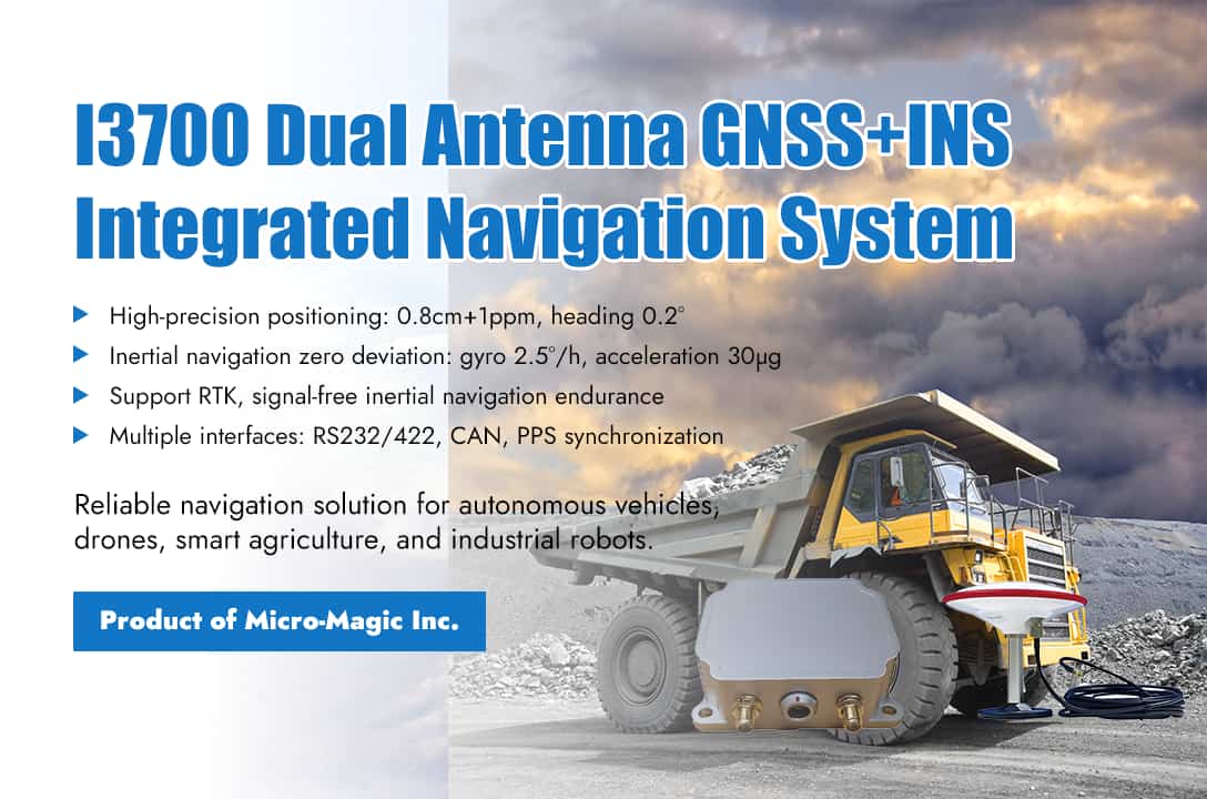
Quickly get the product information in one minute In today's booming development of autonomous driving, drones, and robotics technology, high-precision and highly reliable navigation systems have become the core "brain" of intelligent devices. The MEMS inertial technology combined with dual antenna satellite navigation system I3700 launched by Micro-Magic Inc utilizes high-precision MEMS gyroscopes, accelerometers, and multi-mode multi frequency GNSS receivers to achieve fast and high-precision orientation and integrated navigation functions. It real-time calculates the position, heading, attitude, velocity, and other information of the carrier, resists obstruction and multipath interference, and achieves long-term, high-precision, and high reliability navigation in mountainous tunnels, urban canyon environments, automobiles, high-speed railways, and other areas. Support GNSS real-time RTK function, provide standardized user universal protocol, and have good scalability. Provide convenient navigation solutions for multi domain applications in all scenarios. At the same time, the I3700 has passed IP68 protection and CE certification, and can still work normally in harsh environments, meeting the requirements of industrial grade reliable design. Technical features and highlights of I3700 1. The structural layout of array MEMS-IMU improves the accuracy of attitude calculation To solve the problem of large errors in attitude calculation, an attitude calculation system based on array MEMS-IMU data fusion is proposed. The multi-information vector optimization method is used to fuse the data of the array MEMS-IMU, and the dynamic Kalman filtering method is used to calculate the attitude of the moving carrier. Improve attitude calculation capability to a higher level of accuracy in complex dynamic movements. 2. Support the reception and calculation of GNSS signals across the entire system and frequency band Built in dual antenna positioning and directional GNSS module, supporting all major satellite navigation systems worldwide, capable of high-precision and fast positioning and orientation. Simultaneously compatible with all frequency points, ensuring optimal positioning performance at any location worldwide. The built-in satellite receiver has strong anti-interference ability and can still provide accurate positioning in complex electromagnetic environments. 3. High performance integrated navigation Inertial + GNSS navigation technology combined with self-developed high-precision integrated navigation algorithm achieves a horizontal positioning accuracy of 0.8cm+1ppm and a heading accuracy of 0.2°. Even if GNSS signals are temporarily lost (such as in tunnels or underground garages), stable navigation data can still be continuously output through inertial sensors (gyroscope zero bias stability of 2.5°/h, acceleration zero bias of 30μg). At the same time, multi-source data fusion algorithms support external odometry, DVL and other auxiliary sensors to enhance localization robustness in complex environments. 4. Flexible and easy-to-use interface ecosystem Full interface coverage supports RS232/422, CAN (SAE J1939), PPS synchronization signals, compatible with 4G DTU differential access, easy to interface with external devices such as LiDAR and cameras. Output NMEA, RTCM, binary protocols, and J1939 standard messages, with diverse protocols to meet industrial and vehicle communication needs. 5. Rapid deployment and intelligent configuration The plug and play (PnP) mode makes usage more flexible, with default configurations adapted to mainstream scenarios and support for one click setting of working modes (onboard, shipborne, aircraft, base station). A user-friendly development interface that supports real-time data recording and visual debugging, shortening the integrated development cycle Application scenario: Accurately empowering thousands of industries 1. Drones and unmanned vehicles: In logistics distribution and inspection operations, the I3700 provides centimeter level positioning and stable attitude output to ensure precise control in complex paths. 2. Smart agriculture: combined with agricultural machinery auto drive system, the navigation error between ridges is less than 2cm, greatly improving the efficiency of sowing and fertilization. 3. Ocean exploration and unmanned ships: IP68 protection design to cope with humid salt spray environments, dual antenna directional function to ensure ship heading accuracy, and assist in hydrological surveying and scientific research tasks. 4. Industrial robots: In the scenarios of warehouse AGV and factory handling, millimeter level motion trajectory tracking is achieved by coordinating with external devices through synchronous input and output functions. I3700 provides multiple interface versions (MI0/MI1/MI2) to meet the needs of different industries. Standard development kit and detailed technical documentation, supporting customized services. It can connect to CORS stations such as Qian Xun and Mobile, or build its own RTK reference station to achieve high-precision service coverage nationwide. The I3700 accurately measures the world and controls the future with reliability. Whether you are a developer chasing the forefront of technology or a practitioner deeply involved in the industry, the I3700 will become your reliable partner for exploring intelligent navigation. I3700 Whatever you needs, Micro-Magic is at your side.
Read More
Wheel speed sensors (wheel speed sensors) are often used as auxiliary sensors in inertial navigation systems (INS) to improve navigation accuracy and suppress accumulated errors of inertial sensors. The wheel speed gauge calculates the longitudinal speed of the vehicle by measuring the wheel speed (combined with tire radius and slip ratio correction), providing independent speed information. When GPS signals are lost (such as in tunnels or underground garages), INS can continuously estimate the vehicle's position through dead reckoning by combining the speed data of the wheel speed meter, and compare it with the accelerometer integration results of INS to correct the speed error. In heading calculation, the wheel speed gauge can indirectly calculate the rate of change of heading angle by measuring the speed difference between the left and right wheels (wheel speed difference), providing compensation for the calibration of inertial navigation heading angle. Taking the change of heading angle as an example, this article briefly introduces how to indirectly calculate the rate of change of heading angle through the data obtained from the wheel speed meter. 1. Basic principles Assuming that the vehicle has a rigid body and only moves in a horizontal plane (ignoring pitch and roll), there is no lateral slip at the contact point between the tires and the ground (only considering longitudinal rolling), and the left and right wheelbase (wheel spacing) is a fixed value. The relationship between wheel speed and linear speed is shown in the following equation: When the vehicle turns, the left and right wheels move around the same instantaneous center of rotation (ICR), The vehicle angular velocity is the rate of change in heading angle. The difference in linear velocity between the left and right wheels is generated by the rotation of the vehicle around the ICR, satisfying the following relationship: where: : the wheel spacing , : the turning radius Therefore, there is a difference in linear velocity between the left and right wheels: The rate of change in heading angle (angular velocity) is: 2. Factors affecting the measurement accuracy of wheel speed gauge and algorithm correction In practical applications, the following issues may lead to inaccurate measurement data of the wheel speed gauge, affecting the error compensation of the azimuth angle in INS. a) Track B The actual wheelbase may vary due to load or suspension deformation and requires regular calibration. The above formula assumes that the left and right wheels are symmetrical, so the model needs to be adjusted for asymmetric vehicles. b) Slip and error compensation In wet and slippery road surfaces or off-road environments, or when the vehicle accelerates or brakes rapidly, it may cause tire slippage, resulting in a wheel speed difference that does not match the true angular velocity. Therefore, it is necessary to combine the acceleration and angular velocity data of IMU (Inertial Measurement Unit) to detect the slip state; Dynamically adjust the weight of the wheel speed gauge through multi-sensor fusion algorithm (Kalman filter algorithm) to reduce the impact of slip-on navigation. 3. Actual use cases I3500 is an integrated navigation system (GNSS/INS) produced by Micro-Magic Inc, consisting of high-performance MEMS sensors, high-precision GNSS systems, and high-performance microprocessors. Can be connected to an external odometer, DVL and other auxiliary navigation information, with built-in high reliability integrated navigation algorithms, can output real-time information such as speed, position, and attitude of the carrier. Data input/output Parameters Describe Data Output NMEA/RTCM/Novtel SPAN Binary Protocol Data Content Euler angle, velocity, position, acceleration, angular velocity Fusion Algorithm Extended Kalman Filter External Sensor Mileage meter, GNSS, DTU Integrated navigation accuracy index Position Position Accuracy Velocity Accuracy Pitch/Roll Accuracy Mileage Meter Access 1cm 0.03m/s 0.1° 1m 0.1m/s 0.1° 6m 0.1m/s 0.2° Conclusion The wheel speed gauge complements the inertial navigation system by providing independent speed information, significantly improving the navigation reliability of vehicles in complex environments. Its core values are reflected in: a. Short term accuracy: high-frequency speed data suppresses INS error accumulation. b. Redundant design: Maintain basic navigation capability in the event of GPS failure. c. Cost effectiveness: Significant improvement in navigation performance achieved at a lower cost. In the future, with the advancement of multi-sensor fusion algorithms such as deep learning assisted filtering, The application of wheel speed sensors in autonomous driving and unmanned systems will be further deepened. I3500 High Accuracy 3-Axis MEMS Gyro I3500 Inertial navigation system I3700 High Accuracy Agricultural Gps Tracker Module Consumption Inertial Navigation System Mtk Rtk Gnss Rtk Antenna Rtk Algorithm
Read Moreleave a message
Scan to Wechat :
