




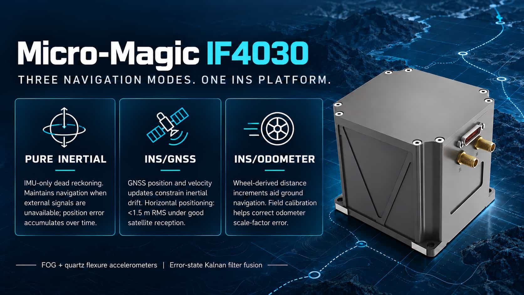
The IF4030 fiber-optic inertial navigation system supports six standardized operating modes, covering typical mission scenarios across land, sea, air, and underwater domains; flexible adaptation is achieved through sensor fusion and algorithmic switching. Pure Inertial Mode Relies entirely on internal gyroscopes and accelerometers for dead reckoning, without external data. Following power-on self-test and a 275-second static alignment, the system enters pure inertial navigation mode, achieving a heading accuracy of 0.1–0.2°/h and a position accuracy of 2.5–6 nmi/h (CEP). Suitable for contingency scenarios such as GNSS-denied environments, tunnels, or areas with strong electromagnetic interference. Inertial/Satellite Integrated Mode Utilizes tight coupling with GNSS (GPS/BDS/GLONASS) observations. When satellite signals are available, horizontal positioning accuracy exceeds 1.5 m and vertical accuracy exceeds 3 m (single-point positioning), with a velocity accuracy of 0.02 m/s (RMS). It supports RTK differential positioning for centimeter-level accuracy and satellite-aided moving-base alignment (approx. 15 minutes). The system maintains continuous output during brief signal outages and automatically converges upon signal re-acquisition; suitable for applications such as UAVs and electro-optical (EO) pods. Inertial/DVL Integrated Mode Integrates velocity data (bottom-track or water-track) from a Doppler Velocity Log (DVL) to effectively suppress velocity drift inherent in pure inertial systems; designed for underwater robots (ROV/AUV) and marine platforms. Supports axis configuration and lever-arm compensation, automatically identifying BS/BI data for velocity matching. Inertial/Odometer Integrated Mode Designed for ground vehicles and track inspection vehicles; integrates pulse signals from wheel odometers to maintain sub-meter/kilometer positioning accuracy in long tunnels or mining areas where satellite signals are unavailable. Supports online scale factor calibration and installation misalignment correction, with automatic storage of calibration parameters via route-based calibration. Inertial/Visual Fusion Mode This mode receives visual odometry or SLAM pose data via Ethernet or serial port; visual data constrains inertial drift, while inertial data smooths out visual noise. It is suitable for UAVs or service robots operating in GNSS-denied indoor environments and requires factory-level joint calibration. Compass (Marine Compass) Mode In this mode, once the inertial navigation system enters the navigation state, it continuously outputs a highly stable heading using purely inertial methods. The core principle involves using a gyro-compassing algorithm to sense the Earth's rotational angular velocity vector and determine True North. It is suitable for surface vessels and operations in polar or high-latitude regions. The system allows users to select the primary fusion scenario (land, marine, or aerial) and configure output priorities via parameter settings. It automatically degrades performance if an auxiliary sensor fails, ensuring continuous and reliable navigation. Real-time mode switching and status monitoring are supported to accommodate diverse mission planning requirements.
Read More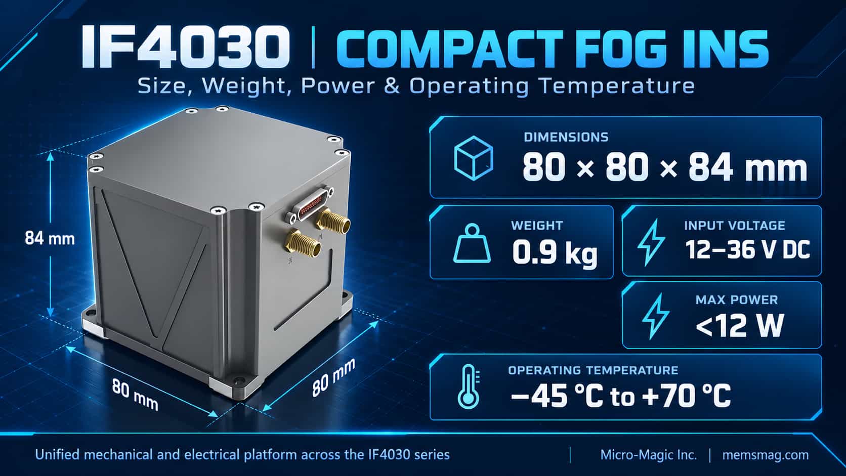
1. Overview The IF4030 series fiber-optic inertial navigation systems are engineered according to SWaP (Size, Weight, and Power) optimization principles—prioritizing miniaturization, lightweight construction, and low power consumption—while maintaining high reliability and the ability to operate across a wide temperature range. Physical dimensions and interfaces are standardized across models of varying precision levels; users do not need to modify mechanical or electrical designs when selecting different precision grades, and this platform-based approach significantly reduces system integration costs. Key specifications include: dimensions of 80 × 80 × 84 mm, a weight of 0.9 kg, a supply voltage of 12–36 V, a maximum power consumption of less than 12 W, an operating temperature range of -45°C to 70°C, and electromagnetic compatibility (EMC) that meets GJB151B standards for Air Force aircraft. 2. Dimensional Analysis The IF4030 is relatively compact compared to similar fiber-optic inertial navigation systems. Through the miniaturization of optical paths and 3D stacked circuit board layouts, its volume has been reduced by approximately 40%, making it particularly suitable for space-constrained applications such as small UAV compartments, electro-optical (EO) pods, and the sealed hulls of underwater robots. The mounting surface requires a flatness better than 0.05 mm, a factor directly influencing attitude output accuracy. An azimuth mounting surface is provided on the side of the housing to ensure precise alignment with the host platform's reference plane. By default, the Y-axis points in the direction of the host platform's forward motion; incorrect installation will result in systematic navigation errors. The coordinate system follows the "Right-Forward-Up" convention, consistent with standard practices in aviation and marine inertial navigation. Its 0.9 kg mass results in a high mechanical resonant frequency, which helps suppress vibration-induced interference on inertial components and minimizes lever-arm effect errors caused by the flexural deformation of mounting brackets. 3. Weight Analysis The unit integrates three fiber-optic gyroscopes, three quartz flexure accelerometers, a power supply module, a data acquisition and processing module, and a satellite navigation module. The power-to-weight ratio is approximately 13 W/kg, performing far better than comparable products, which typically range from 25 W/kg to 40 W/kg. For multi-rotor UAVs, every 100g reduction in weight extends flight endurance by approximately two to three minutes; the 0.9 kg weight significantly frees up payload capacity. Regarding mass distribution, the fiber-optic gyroscope (FOG) assembly accounts for about 35% of the total weight, making it the heaviest component; the three precision variants share a unified platform, with differences in accuracy stemming from fiber length or coil winding techniques rather than structural changes. The aluminum alloy housing accounts for approximately 30% of the weight, balancing structural strength with heat dissipation. 4. Power Consumption Analysis Maximum power consumption is below 12 W; based on a nominal 28 V supply, the typical current draw is approximately 0.43 A. The power distribution is as follows: the FOG light source accounts for about 40% of total power consumption, the accelerometer servo consumes 0.5–1 W, the computing module 2–3 W, the satellite receiver 1–1.5 W, and power conversion losses account for 1–2 W. Power consumption below 12 W reduces heat accumulation in the sealed enclosure. The fanless, passive cooling design eliminates moving parts and enhances long-term reliability, offering particular advantages for battery-powered platforms. Regarding power protection, voltages exceeding 36 V may damage components, while voltages below 12 V trigger an undervoltage lockout (UVLO) resulting in a system reset; the system includes built-in reverse polarity protection and features transient voltage suppression (TVS) devices at the front end. 5. Operating Temperature Range Analysis The wide operating temperature range of -45°C to +70°C complies with the GJB150A military standard, making the system suitable for extreme environments such as high-latitude cold regions, high-altitude UAV operations, and high-temperature desert conditions. FOG bias is highly sensitive to temperature, with drift comprising linear, quadratic, and hysteresis components. For the high-precision model (with a bias stability of 0.06°/h), the residual error after temperature compensation is required to remain within 0.02°/h, assuming a temperature change rate of no more than 1°C per minute. The system utilizes full-temperature-range calibration to store compensation parameters in flash memory, applying real-time compensation based on temperature sensor readings during navigation. 6. Integration Considerations Compared to typical tactical-grade fiber-optic inertial navigation systems, the IF4030 offers a volume reduction of approximately 40%, a weight reduction of over 50%, and a power consumption reduction of about 40%; it operates over a wider temperature range while delivering equivalent accuracy. Key integration requirements include: ensuring the flatness of the mounting surface, as stress-induced deformation can affect the fiber-optic coil's bias stability; limiting the power input to the 12V–36V range and configuring front-end protection and filtering; and ensuring effective thermal conduction between the mounting surface and the structure in high-temperature environments. The standardized form factor allows users to upgrade accuracy without redesigning mounting or power supply configurations.
Read More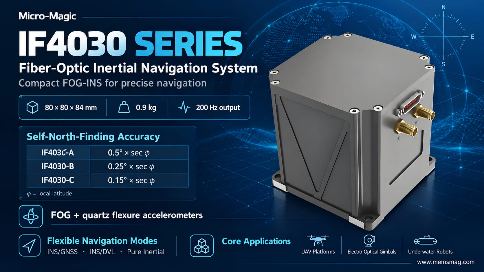
System Positioning and Accuracy Class The IF4030 series comprises high-performance Inertial Navigation Systems (INS) based on fiber-optic gyroscopes (FOG) and quartz flexure accelerometers. Designed to balance miniaturization (80mm × 80mm × 84mm, 0.9kg) with high precision, the series targets platforms such as medium-sized UAVs, optoelectronic pods, and underwater robots—applications that are sensitive to SWaP (Size, Weight, and Power) constraints yet require moderate-to-high navigation accuracy. The series is categorized into three models based on north-finding accuracy: 最小化图片 编辑图片 删除图片 Here, φ represents the local latitude; the fact that the north-finding error increases with latitude is determined by the attenuation of the horizontal component of the Earth's angular velocity (Ω·cosφ) as latitude rises. Since north-finding accuracy is inversely proportional to cosφ, longer integration times or higher-precision gyroscopes are required to compensate in high-latitude regions. Core Parameter Framework and Error Models (1) Inertial Component Specifications 最小化图片 编辑图片 删除图片
Read More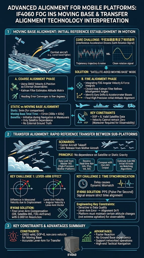
The IF4060 fiber-optic inertial navigation system (INS) not only possesses high-precision autonomous north-finding capabilities but also demonstrates exceptional tactical value through two advanced functions: dynamic base alignment and transfer alignment. These capabilities directly determine the system's rapid response and operational effectiveness when deployed on mobile platforms such as carrier-based aircraft, vehicle-mounted weapon systems, and UAV swarms. 1. Dynamic Base Alignment: Establishing an Initial Reference in a Swaying Environment The primary challenge of dynamic base alignment is that the disturbance accelerations caused by the carrier's motion overwhelm the reference signals—such as the Earth's angular velocity and the gravity vector—typically used for traditional analytical alignment. The IF4060 addresses this issue using a "satellite-aided dynamic alignment" mode, which operates in two stages: Coarse Alignment Stage: Velocity and position data from a satellite navigation system serve as external observations to construct a Kalman filter; this roughly estimates the attitude matrix and converges the heading error to within a few degrees. Fine Alignment Stage: Building upon the coarse alignment, this stage incorporates the INS's integrated angular velocity and specific force data. A closed-loop Kalman filter is used to refine the estimation of misalignment angles while simultaneously identifying gyro drift and accelerometer bias, ultimately achieving high-precision initial attitude initialization. Compared to static base alignment (5 minutes), dynamic base alignment takes approximately 15 minutes (300s + 600s). Although it requires more time, it allows for initialization while the platform is underway or maneuvering; furthermore, the alignment relies entirely on satellite navigation data without requiring an external ground-truth reference. The manual specifies that dynamic base alignment requires valid satellite data and a DOP value of less than 8. Additionally, the carrier's velocity cannot remain constant at zero—meaning a certain level of maneuver-induced excitation is necessary to ensure system observability. 2. Transfer Alignment: Rapid Reference Transfer Between "Parent" and "Child" Platforms Transfer alignment is another advanced feature of the IF4060, designed for "parent-child" platform scenarios—such as aligning carrier-based aircraft before takeoff or aligning a UAV before its release from a mother ship. Its operating principle relies neither on satellites nor static gravity; instead, it receives real-time navigation data (position, velocity, and attitude) from a master inertial navigation system (a high-precision host platform) via a data link. By comparing this data with the output of its own internal inertial navigation system and employing matching algorithms, it back-calculates its own initial attitude and navigation parameters. The core technical challenges of transfer alignment lie in the lever-arm effect and time synchronization. Because the slave and master inertial systems are installed at different locations, differences in linear velocity arise when the carrier maneuvers (lever-arm velocity = angular velocity × lever-arm vector). The IF4060 features a precise lever-arm compensation mechanism (handling DR-to-Inertial, GNSS-to-Inertial, and Inertial-to-Platform lever arms with a resolution of 0.0001 m). This mechanism translates the slave system's measurements to the master system's reference point, thereby eliminating matching errors caused by structural flexure and external lever-arm offsets. Simultaneously, the PPS (Pulse Per Second) signal ensures strict alignment of the time references between the master and slave systems, preventing dynamic mismatches caused by time latency. 3. Key Constraints for Engineering Implementation Both dynamic-base alignment and transfer alignment are highly sensitive to input data quality. During dynamic-base alignment, the system fails to converge effectively if the GNSS velocity reading remains constantly zero or the DOP (Dilution of Precision) value exceeds limits. In transfer alignment, if lever-arm parameters are incorrectly configured, a fault indicator will signal "excessive alignment drift." Furthermore, both alignment modes require the carrier to undergo a certain magnitude of attitude change during maneuvering—avoiding violent oscillation—to ensure the full-state observability of the Kalman filter. Summary The IF4060’s dynamic-base and transfer alignment capabilities essentially extend "static north-finding" to "filter-based estimation in dynamic environments" and expand "autonomous alignment" into "distributed cooperative transfer." These features elevate the IF4060 from a simple position/attitude sensor to a high-end tactical navigation node capable of rapid response within networked combat systems.
Read More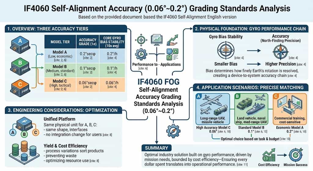
The IF4060 fiber-optic inertial navigation system is available in three models—A, B, and C—corresponding to low, medium, and high precision levels, respectively. Their self-north-seeking heading alignment accuracies (1σ) are 0.2°secφ, 0.1°secφ, and 0.06°secφ. This classification system is not arbitrary; rather, it is based on a comprehensive assessment of core component performance, application requirements, and cost-effectiveness. **Physical Basis for Precision Classification** Self-north-seeking accuracy is fundamentally determined by the bias stability of the inertial components. The gyroscopes in the three IF4060 models feature bias stabilities (10-second average) of 0.2°/h, 0.1°/h, and 0.06°/h, respectively. Gyroscope bias stability is the critical factor governing north-seeking accuracy: the lower the bias, the more precisely the gyroscope can resolve the Earth's angular velocity component, resulting in higher north-seeking accuracy. The three precision tiers correspond directly to the three levels of gyroscope performance, establishing a complete precision chain extending from the component level to the system level. **Industry Positioning of Precision Levels** From an industry perspective, a north-seeking accuracy of 0.06°secφ falls into the high-precision tactical category, capable of meeting demanding requirements such as precision guidance and autonomous UAV navigation. The 0.1°secφ level represents medium-precision tactical grade, suitable for applications like land vehicle and naval vessel navigation. The 0.2°secφ level targets applications that are cost-sensitive and have relatively relaxed precision requirements. Together, these three levels cover the entire spectrum of needs, ranging from "high-end/cutting-edge" to "economical/practical." **Engineering Considerations for Tiered Design** The strategy of offering three precision levels on a single platform reflects mature engineering principles. All three models share identical external characteristics—such as form factor and interfaces—allowing users to switch flexibly between precision levels without altering their system integration schemes. Regarding component selection, fiber-optic gyroscopes naturally exhibit performance variations during production; classifying and shipping products based on actual measured performance is the most economical and rational approach. This method prevents the waste of high-performance components while ensuring that every unit is utilized to its full potential. Precise Matching to Application Scenarios The 0.06° class is suited for missions requiring exceptional heading accuracy, such as long-range UAV reconnaissance and missile launcher alignment. The 0.1° class meets the needs of most tactical vehicles, naval navigation systems, and short-to-medium-range UAVs. The 0.2° class is appropriate for civil or training applications where cost control is strict and accuracy requirements are moderate. Users can select the optimal option from these three accuracy tiers based on mission requirements and budget constraints. The IF4060’s three-tier accuracy classification represents an optimal solution—grounded in gyroscope performance, driven by application needs, and balanced by cost-effectiveness—ensuring that every penny is spent where it counts most.
Read More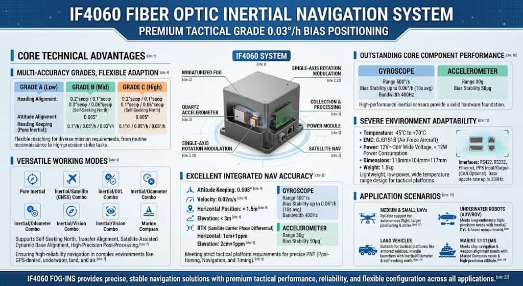
The IF4060 fiber-optic inertial navigation system (INS) is a single-axis rotation-modulated system primarily composed of a miniaturized fiber-optic gyroscope, quartz accelerometers, a servo mechanism, a power supply module, a data acquisition and processing module, and a satellite navigation module. Characterized by its compact size, light weight, high precision, and low cost, the product is capable of self-calibrating certain inertial component errors. As a high-end tactical-grade INS, the IF4060 is suitable for a wide range of demanding applications, including small-to-medium-sized UAVs and underwater robots. Core Technical Advantages 1. Multiple Precision Levels for Flexible Adaptation The IF4060 is available in three models—A, B, and C—corresponding to low, medium, and high precision levels, respectively; they share identical external characteristics, such as form factor and interfaces. Heading alignment accuracies are 0.2°secφ, 0.1°secφ, and 0.06°secφ (self-north-seeking), respectively; attitude alignment accuracy is 0.005° across all models; and heading hold accuracy (pure inertial mode) is 0.1°/h, 0.05°/h, and 0.03°/h, respectively. This three-tier precision design allows the IF4060 to flexibly meet the varying navigation accuracy requirements of different missions, handling everything from routine reconnaissance to high-precision strike operations. 2. Comprehensive Operating Modes The IF4060 supports multiple operating modes, including pure inertial, inertial/satellite, inertial/DVL, inertial/odometer, inertial/visual, and marine compass modes. It also supports functions such as self-north-seeking, transfer alignment, satellite-aided moving-base alignment, and high-precision post-processing. This comprehensive mode coverage ensures highly reliable navigation capabilities in complex environments—including GPS-denied, underwater, land, and aerial scenarios—fully meeting the adaptability requirements of tactical-grade products for complex battlefield conditions. 3. Excellent Integrated Navigation Precision In satellite-integrated navigation mode, attitude hold accuracy reaches 0.008°, velocity accuracy is 0.02 m/s, horizontal position accuracy is better than 1.5 m, and vertical position accuracy is better than 3 m. When utilizing a satellite carrier-phase differential link, the system achieves a horizontal accuracy of 1 cm + 1 ppm and a vertical accuracy of 2 cm + 1 ppm. This exceptional level of integrated navigation precision ensures the IF4060 fully meets the rigorous requirements for precise positioning, navigation, and timing (PNT) demanded by tactical-grade combat platforms. 4. Superior Core Component Performance The IF4060 is equipped with a gyroscope featuring a measurement range of 500°/s, a bias stability of up to 0.06°/h (10s average), and a bandwidth of 400 Hz; the accelerometer offers a measurement range of 30g and a bias stability of 50 μg. These high-performance inertial components provide a robust hardware foundation for the system's high-precision navigation capabilities. Adaptable to Harsh Environments and Tactical Demands The IF4060 operates within a temperature range of -45°C to +70°C, and its electromagnetic compatibility complies with the GJB151B standards for Air Force aircraft. It supports a wide input voltage range of 12V to 36V and consumes less than 12W of power. With dimensions of 118mm × 104mm × 117mm and a weight of only 1.8 kg, its lightweight, low-power, and wide-temperature design allows for flexible integration and deployment across various tactical platforms. Regarding interfaces, the IF4060 provides RS422, RS232, Ethernet, and PPS input/output ports, with customizable CAN interface options available. It supports a data update rate of up to 200 Hz, ensuring real-time responsiveness in highly dynamic operational scenarios. Application Scenarios Leveraging the aforementioned superior performance, the IF4060 fiber-optic inertial navigation system is widely used in: Small and medium-sized UAVs: Its lightweight design combined with high-precision navigation capabilities ensures reliable autonomous flight, target positioning, and engagement; Underwater robots: Integrated Inertial/DVL navigation and heave measurement capabilities meet the requirements for long-endurance, high-precision underwater navigation; Land vehicles: Integrated Inertial/Odometer navigation combined with an automatic north-finding function makes it suitable for tactical platforms such as armored vehicles and missile launchers; Marine systems: Marine compass modes and high-precision attitude measurement meet the needs of ship navigation and weapon system alignment. Conclusion With its single-axis rotation modulation technology, core components comprising high-performance fiber-optic gyroscopes and quartz accelerometers, flexible configuration across precision grades, comprehensive operational modes, and superior integrated navigation accuracy, the IF4060 establishes itself as a high-end tactical-grade inertial navigation system. Whether for UAVs, underwater robots, land vehicles, or marine systems, the IF4060 delivers precise and stable navigation solutions through exceptional performance, reliable environmental adaptability, and flexible configuration capabilities.
Read More
1. Introduction: Technological Landscape and Market Overview of Inertial Navigation Systems As an autonomous navigation technology that does not rely on external signals, Inertial Navigation Systems (INS) are experiencing unprecedented growth driven by the rapid advancement of frontier technologies such as artificial intelligence, autonomous driving, and commercial aerospace. Amidst fierce market competition and rapid technological evolution, Micro-Electro-Mechanical Systems (MEMS) and Fiber Optic Gyroscopes (FOG) have emerged as the two dominant technological pathways in the INS sector. Each offers distinct advantages; consequently, selecting the right technology for specific application scenarios has become a critical challenge for engineers and procurement teams. The choice between MEMS and FOG is not merely a contest of technical performance specifications but requires a comprehensive evaluation of mission duration, environmental conditions, precision thresholds, SWaP (Size, Weight, and Power) constraints, and budget. 2. Core Comparison: MEMS INS vs. Fiber Optic INS 2.1. Operating Principles and Technical Differences MEMS INS relies on micro-scale capacitive or piezoresistive structures to measure motion by detecting mechanical displacement; these systems can be packaged at the chip level, enabling low-cost, mass production. In contrast, Fiber Optic INS utilizes the Sagnac effect, employing kilometer-long optical fiber coils to detect rotation; its all-solid-state design ensures a long service life and resilience in extreme environments. The primary advantage of Fiber Optic INS is high precision—achieving bias stability as low as 0.001°/h and maintaining navigation capabilities for tens of minutes to several hours following a loss of GNSS signal. MEMS INS excels in extreme miniaturization, low power consumption, cost-effectiveness, instant startup, and high shock resistance. In recent years, the drift rate of tactical-grade MEMS has dropped to a few degrees per hour, and high-end products can maintain an attitude accuracy of 0.01° during a 60-second GNSS outage, steadily narrowing the performance gap with Fiber Optic INS. 3. In-depth Analysis of MEMS INS Application Scenarios 3.1. UAVs and the Low-Altitude Economy Consumer-grade and logistics drones represent key application scenarios for MEMS INS. In environments with weak GNSS signals—such as forests, underground parking facilities, and urban canyons—MEMS IMUs provide drones with continuous and precise pose (position and orientation) data. For small and medium-sized drones with flight times under 40 minutes, their lightweight and low-power characteristics align perfectly with SWaP (Size, Weight, and Power) requirements; furthermore, they have seen annual order growth exceeding 200% in emerging sectors such as low-altitude logistics and unmanned inspections. 3.2. Autonomous Driving and Smart Vehicles Intelligent driving has become the largest source of growth in the civil inertial navigation market. In practical applications, vehicles equipped with MEMS IMU modules can achieve continuous, precise positioning—keeping errors within 8 centimeters—even in areas where satellite signals are completely lost, such as three-level underground parking garages, thereby successfully executing autonomous parking. MEMS INS technology meets the precision requirements of most high-precision, industrial, and consumer-grade applications, offering "sufficient" accuracy through exceptional cost control. 3.3. Robotics and Physical Agents As the commercialization of intelligent equipment—such as humanoid robots, robot dogs, and AGVs—accelerates, market demand for inertial attitude sensors has experienced structural growth, given their role as the "balance nerves" and "cerebellum" of robots. When robots traverse complex terrain, GNSS signals may be interrupted; MEMS INS provides precise orientation to ensure stable operation. In industrial automation, MEMS INS has become an industry standard for tasks ranging from AGV autonomous navigation to industrial robotic arm attitude control, thanks to its compact size and low cost. 3.4. Precision Agriculture and Surveying While agricultural drones and autonomous farm machinery have relatively moderate requirements for navigation system precision, they demand high resilience against vibration, temperature fluctuations, and environmental contaminants. MEMS INS has become the mainstream choice in precision agriculture due to its excellent shock resistance and cost-effectiveness. From seeding monitoring to variable-rate fertilization, MEMS INS provides agricultural equipment with stable, reliable pose-sensing capabilities; moreover, the low cost per unit—compared to fiber-optic solutions—makes large-scale commercial deployment feasible. 4. In-depth Analysis of Fiber-Optic INS Application Scenarios 4.1. Aerospace and Defense Equipment Fiber-optic INS applications in the aerospace and defense sectors represent the "gold standard." Whether for high-dynamic tactical missiles, satellite attitude control, or navigation systems for large transport aircraft and fighter jets, fiber-optic gyroscopes (FOGs)—with their exceptionally low bias drift and superior long-term stability—remain indispensable core components. In the aerospace sector, fiber-optic inertial navigation systems (INS) operate independently of external radiation sources and are unaffected by geography, weather, or harsh environments; their operational scope spans aerospace, land surface, underground, open oceans, and even the deep sea. For instance, navigation and control systems for high-dynamic platforms based on FOG technology possess robust capabilities in vehicle navigation and control, finding widespread application in tactical missiles and satellite platforms. In the defense sector, FOGs serve as core components for strategic equipment such as missile guidance systems, military UAVs, and naval vessel attitude control systems, making them a key focus of international technology export controls. 4.2. Marine Navigation and Unmanned Underwater Systems For marine platforms such as deep-sea autonomous underwater vehicles (AUVs), unmanned underwater vehicles (UUVs), and surface vessels, satellite navigation signals often fail to penetrate the water; in such scenarios, fiber-optic INS becomes the sole navigation option. Fiber-optic INS can achieve a pure inertial navigation positional accuracy of better than 1 nautical mile (RMS) over one hour and a heading error of no more than 1 degree over 72 hours—capabilities that are critical for underwater missions lasting days or even weeks. State-of-the-art products also feature "north-seeking" capabilities, allowing them to rapidly determine true north in environments devoid of GNSS signals or free from magnetic interference, thereby serving as a cornerstone for shipborne navigation and underwater exploration. Fiber-optic gyro-based inertial navigation systems have become essential for maintaining mission stability in unmanned vehicles operating amidst high winds, complex terrain, and electronic warfare environments. 4.3. High-Speed Rail Track Inspection and Heavy Engineering High-speed rail track inspection imposes extremely stringent accuracy requirements on navigation systems, necessitating millimeter-level precision in the measurement of track geometric parameters. Thanks to their superior long-term stability and low-drift characteristics, fiber-optic INS units have become standard equipment on railway maintenance and inspection vehicles; these products are widely applicable across sectors ranging from high-speed rail track inspection to civil industries such as oil and gas, and coal mining. In scenarios where GNSS signals are completely unavailable—such as underground mines and tunnels—fiber-optic hybrid navigation systems have achieved positioning accuracy better than 0.1% of the distance traveled, maintaining stable, continuous operation in complex environments as deep as 1.4 kilometers underground. 4.4. Ocean-going Vessels and Offshore Platforms Navigation systems for ocean-going vessels must withstand months or even years of continuous maritime operation; any navigation failure could lead to catastrophic consequences. Thanks to their all-solid-state structure, absence of rotating friction components, exceptionally long service life, and high resistance to electromagnetic interference, fiber-optic INS units serve as a "trusted anchor" for marine inertial navigation. In high-precision applications such as offshore drilling platforms and dynamic positioning (DP) systems, fiber-optic gyro systems provide continuous attitude and heading references, ensuring the safety and efficiency of offshore operations. Offshore oil drilling platforms operating in the open ocean—where GNSS signals cannot be relied upon—also require the absolute orientation references provided by fiber-optic INS. 5. Integrated Selection and Decision-Making Framework Regarding cost, the significantly lower cost of MEMS INS has the potential to transition inertial navigation technology from a "military luxury" to the realm of civilian consumer products. A single tactical-grade MEMS system costs in the range of a few thousand dollars, whereas a navigation-grade fiber-optic INS can cost tens or even hundreds of thousands of dollars. If the project budget is limited and accuracy requirements are of moderate priority, MEMS INS is the more pragmatic choice. Regarding accuracy and stability, fiber-optic INS is required if positioning accuracy within a few hundred meters must be maintained for more than 30 minutes following a loss of GNSS signal. However, if mission durations are typically under 15 minutes and satellite signals are generally available, a high-performance MEMS INS is fully capable of handling the task. Regarding SWaP (Size, Weight, and Power) constraints, MEMS INS units are far superior to fiber-optic solutions, making them the ideal choice for drones, wearable devices, and microrobots. Although fiber-optic INS units have been significantly reduced in size through compact design, they still cannot compete with chip-scale MEMS in terms of miniaturization. Regarding environmental adaptability... MEMS INS offers exceptional shock resistance, making it suitable for applications involving vehicle turbulence or the intense vibrations experienced by drones; in contrast, fiber-optic INS excels in harsh environments characterized by extreme temperatures, high deep-sea pressures, and strong electromagnetic interference. Conclusion MEMS INS and fiber-optic INS represent two distinct evolutionary paths in inertial navigation technology. Leveraging the extreme integration of chip-based technology, MEMS has brought inertial navigation to mass-market civilian applications such as automobiles, drones, and robotics. Meanwhile, fiber-optic technology—drawing on the essence of all-solid-state optics—maintains the pinnacle of precision and reliability in cutting-edge sectors like aerospace, deep-sea exploration, and defense equipment. For engineers and procurement decision-makers, the crucial takeaway is that there is no single "best" technology—only the technology best suited to the specific application. A truly sound selection decision requires a balanced consideration of mission requirements, environmental challenges, and budget constraints.
Read More
At the bottom of an open-pit mine with a depth of over 200 meters, towering rock walls surround it on all sides. A 300 ton unmanned mining truck is carrying out stripping operations, but it is facing the dilemma of severe satellite signal obstruction: GPS signals are intermittent, RTK fixed solutions are frequently degraded, ordinary integrated navigation systems can produce enough drift to deviate from the lane within a few minutes, and the mining truck has deep mining areas on one side and hard rock walls on the other. Any positioning deviation may cause serious accidents. This is the core scenario in which the I7200 high-precision integrated navigation system produced by Micro-Magic Inc is designed - how to rely on the combination of inertia and odometer to maintain lane level positioning accuracy for unmanned vehicles in an environment where satellite signals are systematically rejected. The confidence of I7200 first comes from its ultra-high precision gyroscope. In pure inertial mode after the disappearance of GNSS signals, most MEMS integrated navigation systems accumulate several meters of lateral error within sixty seconds, which is sufficient for mining trucks to deviate from the lane. The gyroscope of I7200 achieves zero bias stability of ≤ 0.1 °/h, zero bias instability of ≤ 0.02 °/h, and angle random walk of ≤ 0.01 °/√ h. This means that within 60 seconds without satellite signals, its heading drift is controlled within 1°. With the zero bias stability of ≤ 30μg and the zero bias instability of ≤ 10 μg of the accelerometer, the system can accurately perceive every pitch and roll of the vehicle on bumpy roads, and convert these small movements into accurate displacement calculations. By integrating external information such as odometry and kinematic constraint algorithms, the I7200 achieves a pure inertial positioning accuracy of ≤1 meter within 60 seconds after GNSS signal loss. This level of accuracy is just within the safety margin for maintaining lane keeping on mining trucks. The self-north-seeking capability is another underestimated yet critical feature. The I7200 supports autonomous north-seeking with an accuracy of ≤1°, allowing mining trucks to complete heading initialization while stationary without any additional operations. For mining trucks that rotate among multiple vehicles, this feature significantly simplifies the deployment process. On a deeper level, the design logic of I7200 responds to a core contradiction in the industrialization of autonomous driving: high-precision sensors have superior performance but high cost, while low-cost sensors lack reliability in complex environments. The I7200 benchmarks fiber optic gyroscope grade products in key indicators of gyroscopes and accelerometers - with a full temperature zero bias of ≤ 0.5 °/h and an accelerometer full temperature zero bias of ≤ 1mg - while maintaining the low cost and small size advantages of MEMS solutions. The size of 93mm×85mm×49.5mm and the weight of less than 500 grams allow it to be flexibly installed in the cab or protective box of the mining truck, and the steady-state power consumption of 4W does not even require separate consideration of heat dissipation design. This is the value that I7200 brings to autonomous driving: not to make the vehicle fly faster under ideal conditions, but to let it know where it is in the most dangerous moments.
Read More
The indirect calculation of heading angle through wheel speed difference is a simplified version of the classic "wheel speed odometer" method in vehicle dynamics. The core principle is to use the speed difference between the left and right wheels, combined with the vehicle's wheelbase, to calculate the angular velocity of the vehicle rotating around the vertical axis, and integrate it to obtain the heading angle. The specific implementation method is as follows: (1) Calculate instantaneous yaw rate based on the linear velocity of the left and right wheels Read the left rear wheel speed and right rear wheel speed (unit: rad/s), and calculate the linear velocity of the left and right wheels based on the wheelbase L (unit: m) and tire rolling radius r (unit: m): ; ; Directly using this formula will face many practical problems in reality, and algorithm level correction of steering geometry and compensation for sideslip and nonlinear regions are also required. Steering geometry correction (Ackermann steering geometry) typically uses the wheel speed of the non steering axis (usually the rear axle) to calculate the rate of change in heading angle. Side slip and nonlinear compensation usually involve the fusion of wheel speed difference calculation with IMU (Inertial Measurement Unit) gyroscope data (such as Kalman filtering), using wheel speed difference to correct the gyroscope's zero bias drift, and using the gyroscope to compensate for the dynamic delay of wheel speed calculation. (1) Signal processing When driving at low speeds, the speed difference between the left and right wheels is very small. If the resolution of the wheel speed pulse counter is insufficient, it will cause the calculated heading angle change rate to jump severely. Low pass filtering is required to remove high-frequency noise using first-order low-pass filtering. (2) Integrating to calculate heading angle In this way, high-precision estimation of heading angle change rate can be obtained solely through wheel speed sensors under low-speed and quasi-static conditions, which is of great value for short-term positioning and Dead Reckoning.
Read More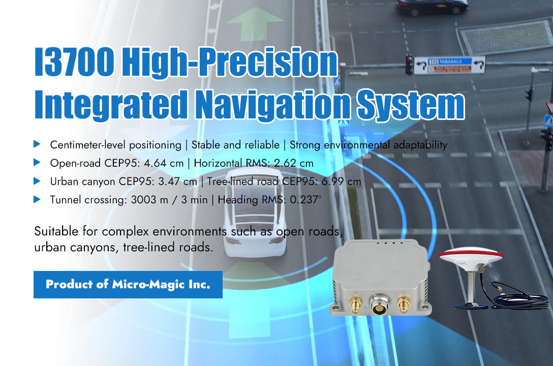
To fully verify the performance of the I3700 integrated navigation system in real-world application scenarios, Micro-Magic Inc conducted a comprehensive and rigorous product performance test in response to customer requirements. The testing covers six typical scenarios including open roads, urban canyons, tree-lined roads, underground garages, long tunnels, and elevated auxiliary roads, comprehensively evaluating the positioning accuracy and stability of the system in various complex environments. This test uses the NovAte PwrPak7D-E1 high-precision integrated navigation system as the true value reference, and uses Waypoint Inertial Explorer professional software for post-processing and smoothing calculations to ensure the high reliability and centimeter level accuracy of the test data. The test results show that in an open environment with good satellite signals, the I3700 has a CEP95 (95% positioning error) of only 4.64 centimeters and a horizontal RMS error of 2.62 centimeters. The system availability is as high as 100%, achieving true centimeter level positioning. In environments with severe signal obstruction such as urban canyons and tree-lined roads, I3700 still performs robustly, with CEP95 reaching 3.47 cm and 6.99 cm respectively, and horizontal RMS error controlled at 1.79 cm and 4.77 cm, fully demonstrating its strong multipath suppression and signal recovery capabilities. In the more challenging scenario of complete loss of GNSS signal lock, the pure inertial navigation performance of I3700 becomes the biggest highlight. In the high-speed tunnel crossing test that lasted for about 3 minutes and was 3003 meters long, the system's horizontal positioning RMS was 4.28 meters, speed RMS was 6.57 centimeters per second, and heading angle RMS remained stable at 0.237 °, fully demonstrating its excellent drift control capability in long-term, high dynamic GNSS denial environments. The I3700 integrated navigation system integrates high-performance MEMS-IMU and full constellation, full frequency dual antenna RTK GNSS receiver. The gyroscope has a zero bias instability of 1.6°/h and the accelerometer has a zero bias instability of 18 μ g; RTK positioning accuracy can reach 1 centimeter, and dual antenna direction finding accuracy is 0.2° (1-meter baseline); Achieving 100% availability in open environments, maintaining high-precision output even in signal occlusion and loss of lock scenarios, suitable for various high-end application scenarios such as drones, unmanned ships, autonomous driving, agricultural machinery, and satellite communication antenna stabilization platforms. Micro-Magic Inc stated that the I3700 integrated navigation system demonstrated excellent comprehensive performance in this rigorous test, not only achieving centimeter level positioning in open environments, but also maintaining stable and reliable pose output under extreme conditions of GNSS signal loss with powerful inertial navigation algorithms. Its excellent environmental adaptability and positioning accuracy fully meet the urgent demand of current intelligent equipment for high-precision and high reliability navigation systems.
Read More
In the development of new-generation fighter jets, missiles, and hypersonic vehicles, flight testing is a critical step to validate their extreme performance and flight envelope. Such aircraft often feature extremely high speeds, intense maneuvering overloads, and complex flight trajectories, imposing stringent demands on their onboard navigation systems. These systems must not only deliver real-time, stable, and high-precision navigation outputs under highly dynamic conditions but also be capable of comprehensively and faithfully recording every millisecond of flight details, providing an indisputable data foundation for post-flight performance analysis and design iteration. The IF3900 high-precision fiber optic gyro inertial navigation system, developed by Micro-Magic Inc., features a mature solution to this challenge with its exceptional 0.001°/h bias stability and a high-precision quartz accelerometer of 10μg level, combined with unique multi-sensor fusion and post-processing technologies. The core advantage of the IF3900 system lies in its construction of a complete data value chain from real-time perception to post event deep analysis. During the test flight, the system captures every subtle angular and linear motion of the aircraft in real time with its wide dynamic range gyroscope of ±500°/s and accelerometer of ±30g. By deeply coupling with GNSS satellite signals, the system can output fused navigation results with an update rate of up to 800Hz, real-time attitude accuracy better than 0.002°, and velocity accuracy of 0.02m/s, providing reliable situational awareness for test pilots and ground command centers. However, what truly distinguishes IF3900 from traditional inertial navigation is its powerful post-processing capabilities. This function allows researchers to perform joint precision calculations between the raw inertial measurement unit (IMU) data and raw satellite observation data recorded on board and ground differential reference station data after the test flight is completed. This process can effectively eliminate unavoidable instantaneous signal interference, multipath effects, and cumulative inertial sensor errors in real-time navigation, thereby advancing the accuracy of trajectory, attitude, and velocity calculations to a new level. The system supports recording raw data streams through built-in SD cards or external high-speed serial ports, and its data format is compatible with industry standard post-processing software (such as Novatel Inertial Explorer), ensuring smooth and professional data analysis processes. To achieve this goal, IF3900 has laid a solid foundation at the hardware level. The closed-loop fiber optic gyroscope and quartz accelerometer used can withstand a half sine shock of 30g , 11ms, and meet the high-intensity vibration conditions required in extreme environments such as fighter mounting and missile launch, ensuring that the system always operates stably and reliably in real high shock and strong vibration scenarios. During hypersonic aircraft turning maneuvers or high angle-of-attack agility testing of fighter jets, the flight state changes rapidly and the environment is extremely complex. The value of the IF3900 lies in its ability to not only clearly 'see' this moment, but also provide a reliable 'flight record' through post-processing 'review' of every moment. Technical experts at Micro-Magic Inc stated that this file is the most critical basis for analyzing aerodynamic characteristics, evaluating control systems, and even verifying weapon delivery accuracy. As the aerospace industry moves towards higher, faster, and smarter directions, the requirements for the quality and depth of test flight data are also increasing. The IF3900 high-precision fiber optic inertial navigation system, with its hardcore sensor specifications, robust environmental adaptability, and groundbreaking post-processing capabilities, is becoming an indispensable high-precision data engine for driving the new generation of aircraft from flight testing to finalization.
Read More
Significant progress has been made in the field of inertial technology in China - Micro Magic Inc recently announced that its high-performance inertial navigation system IF3700 has been successfully applied to the industry-leading "Tianhang Intelligence" new generation high-end industrial drone platform. This cooperation marks a comprehensive breakthrough in key indicators such as adaptability to complex environments and long-term stability for domestically produced high-precision inertial sensors, providing a core guarantee for reliable operation of industrial drones in challenging scenarios. In professional scenarios such as power inspection, high-altitude surveying, and emergency reconnaissance, industrial drones often face severe challenges such as strong electromagnetic interference, severe temperature changes, and continuous body vibration. The performance fluctuations of traditional sensors can easily lead to positioning drift and attitude misalignment, directly affecting operational safety and data quality. The technical director of "Tianhang Intelligence" said, "We have been looking for a sensor that can provide stable and accurate heading and attitude measurement throughout the entire mission cycle, and the appearance of IF3700 is timely." The successful application of IF3700 is attributed to its outstanding performance in multiple key performance parameters, which directly determine the reliability of drone navigation systems under extreme conditions. The IF3700 adopts a high-precision closed-loop fiber optic gyroscope with a full temperature of 0.01°/h and a 20 μg high-precision quartz accelerometer, with autonomous compass function. It can still achieve attitude accuracy of ≤ 0.003° and heading maintenance accuracy of ≤ 0.01°/h in pure inertia mode, demonstrating strong environmental adaptability. At the same time, the system supports inertial/satellite integrated navigation mode, with a position accuracy of centimeter level (RTK mode) and a velocity accuracy of better than 0.02m/s, effectively improving the operational capability of unmanned aerial vehicles in GNSS signal interference prone areas such as urban canyons and forest areas. In addition, IF3700 has rich interface configuration and high data update rate (up to 800Hz), which can flexibly interface with flight control, load and ground station systems, meeting the strict requirements of real-time and integration for industrial grade drones. The "Tianhang Intelligent" drone equipped with the IF3700 inertial navigation system has been validated for its value in multiple harsh scenarios. In surveying missions over complex plateau terrain, even with weak GPS signals, the IF3700 maintained centimeter-level flight path accuracy through its stable system output, successfully accomplishing high-precision 3D modeling. During high-voltage live-line inspection tasks, even when operating in strong electromagnetic environments, the IF3700 system remained completely immune to interference, delivering robust and reliable navigation and attitude data that formed the core foundation for autonomous obstacle avoidance and precise hovering. In emergency supply delivery operations, despite enduring substantial temperature variations during long-endurance, day-and-night missions, the IF3700 system demonstrated exceptional temperature stability, ensuring no degradation in navigation accuracy throughout the entire process. Micro Magic's Product Manager stated: "The success of the IF3700 system in the high-end industrial drone sector is just the beginning. It demonstrates that domestic core sensors are fully capable of supporting the development needs of intelligent equipment. We will continue to deepen our expertise in inertial technology, providing more unmanned platforms with a precise and reliable 'Perception Heart'."
Read Moreleave a message
Scan to Wechat :
