




1. Introduction:
Imagine a scenario where a welding robot operates continuously on an automotive assembly line, with the end of its robotic arm subjected to instantaneous shocks of 15g at a frequency of 80Hz. In this context, if the wrong IMU is selected, the bias drift of a standard sensor could accumulate to 1.2° within just 30 minutes, leading to positioning failure and a safety shutdown.
This is no exaggeration. In high-vibration industrial environments—whether in stamping workshops, CNC machining, heavy-duty AGV operations, or heavy construction machinery—the challenge facing IMU sensors is not merely a matter of precision, but of fundamental viability.
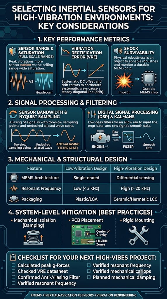
Vibration affects IMUs primarily through two channels: first, direct mechanical coupling, where vibration transmits through the mounting base to the sensor, interfering with the response of its micromechanical structure; second, Vibration Rectification Error (VRE), where the accelerometer’s DC rectification response to AC vibration generates an additional offset—a particularly critical issue for tilt-sensing applications. Furthermore, industrial environments experience drastic temperature fluctuations (-40°C to 85°C); since MEMS sensors are highly temperature-sensitive, an uncompensated gyroscope can exhibit bias drift on the order of ±10°/s.
Therefore, selecting an IMU for high-vibration conditions requires addressing two core issues simultaneously: vibration interference resistance and temperature drift compensation. This article explores these two key aspects, systematically outlining the critical technical specifications and the decision-making process for product selection.
2. The Nature of Vibration Interference and Anti-Vibration Strategies
2.1. Understanding Vibration Rectification Error (VRE)
In high-vibration environments, the most common failure mode for an IMU is not simply "inaccurate measurement," but rather "bias shift caused by vibration"—this is known as Vibration Rectification Error (VRE). For accelerometers, the sensor produces an unintended DC offset in response to AC vibration; such DC offsets are particularly detrimental in tilt-sensing applications. For gyroscopes, the primary issue is g-sensitivity, where linear vibration couples through the device's mechanical structure to superimpose a spurious angular rate signal onto the gyroscope's output. The combined effect of these issues can range from attitude drift to complete control system instability. 2.2. Mitigating Vibration at the Hardware Level
When selecting products, priority should be given to IMUs featuring hardware-level vibration resistance designs rather than standard models that merely boast impressive specifications. The following vibration-resistant design features are key selection criteria:
(1) Differential/Closed-Loop Sensing Architecture
IMUs employing a differential gyroscope architecture can effectively suppress interference from linear acceleration and mechanical vibration. Closed-loop MEMS structures, combined with independent temperature compensation channels between the MEMS element and the ASIC circuitry, also significantly enhance vibration resistance.
(2) Mechanical Filters and Vibration-Immune Designs
Some industrial-grade sensors incorporate on-chip mechanical filters to attenuate high-frequency environmental vibration interference. For instance, Murata’s SCA3400 accelerometer utilizes a "vibration-immune design" capable of suppressing environmental vibration interference above 200 Hz.
(3) Physical Isolation and Reinforced Packaging
A dual-layer metal-ceramic housing combined with specialized damping materials can suppress mechanical noise coupling. The U4930 from Maixinmin Micro employs a hermetically sealed metal housing with specialized damping materials, suppressing mechanical noise interference while maintaining an IP67 protection rating.
(4) Redundant Sensor Architecture
A dual-IMU redundant architecture compensates for errors through real-time data comparison, further enhancing output reliability in high-vibration environments.
2.3. Suppressing Vibration Noise via Algorithms
Even with optimal hardware selection, vibration noise cannot be entirely eliminated. Robust vibration-resistance solutions invariably incorporate noise reduction processing at the algorithmic level.
(1) Adaptive Bandwidth Filtering
One cutting-edge approach involves adaptive data preprocessing, where the filtering bandwidth is continuously adjusted via sinusoidal estimation to mitigate the impact of vibration and sensor noise prior to attitude estimation. Adaptive Kalman filter modules can dynamically adjust the noise covariance matrix and automatically optimize weighting based on external vibration frequencies, achieving an output noise density as low as 0.008°/s/√Hz. (2) Combination of Wavelet Filtering and Kalman Filtering
Research indicates that by employing Gaussian-weighted moving average filtering combined with wavelet filtering for initial noise suppression, followed by PID-based fusion of the denoised data, and finally further optimization via Kalman filtering, the standard deviation of vibration noise can be reduced by 93.83%.
(3) LMS and Extended Kalman Filter (EKF) Method
For vibration scenarios such as vehicle bodies, the Least Mean Square (LMS) method can be used for front-end preprocessing to enhance the signal-to-noise ratio. Subsequently, the complementary characteristics of accelerometers and gyroscopes are utilized to filter out gyroscope bias noise, followed by final filtering using an Extended Kalman Filter. Results from a four-hour field experiment demonstrate that this method significantly reduces the impact of vehicle vibration on the IMU.
2.4. Key Selection Criteria for Vibration Environments
When selecting a device, particular attention should be paid to the following vibration-related technical parameters:
` Vibration Rectification Error (VRE) / Vibration Rectification Coefficient: This is the most direct indicator of vibration resistance, typically measured in mg/g². Lower values indicate superior vibration resistance.
` Vibration Resistance: Expressed in grms (e.g., ≥20 grms or 10 g RMS over the 20 Hz–2 kHz range).
` Bandwidth Selection: Select a bandwidth that matches the target vibration frequency. An excessively wide bandwidth captures high-frequency in-band vibration, leading to higher VRE. Industrial-grade IMUs often intentionally limit output bandwidth to 100–200 Hz as an anti-aliasing design measure.
` Shock Tolerance: Typically required to be ≥2000 g or higher to ensure that accidental, severe shocks do not damage the IMU.
3. Temperature Drift Compensation Strategies and Accuracy
3.1. How Significant is the Impact of Temperature on IMUs?
The sensitive structures of MEMS accelerometers and gyroscopes (such as silicon-based micromechanical beams, proof masses, and capacitive plates) undergo thermal expansion and contraction with temperature changes. This alters mechanical stiffness and capacitive gaps, resulting in output signal drift. For example, the Young's modulus of silicon decreases at a rate of approximately -60 ppm/°C as temperature rises; within the -40°C to 85°C range, the uncompensated bias drift of a gyroscope can reach the order of ±10°/s. Therefore, when selecting a device, one must focus on the IMU's stability across the full temperature range rather than relying solely on room-temperature specifications.
3.2. Technical Approaches to Temperature Drift Compensation
Currently, there are two main technical paths for temperature drift compensation:
Path 1: Hardware-level temperature compensation
This involves integrating independent temperature sensors and compensation channels to monitor temperature and correct the output in real-time within the chip. Digital closed-loop systems are used to correct drift in real-time; for instance, the self-compensation feature in certain industrial-grade accelerometers can suppress temperature drift to ±0.003 mg/°C. Wafer-level encapsulation techniques and the selection of highly stable packaging materials help reduce thermal stress within the package.
Path 2: Software/algorithm-level temperature compensation
Software compensation relies on mathematical methods to analyze the relationship between temperature and the MEMS gyroscope's output data. It ensures output accuracy without incurring additional hardware costs, offering advantages such as simplicity, lower cost, and ease of parameter adjustment.
Mainstream methods include polynomial fitting, piecewise linear/piecewise fitting, and interpolation techniques (such as Lagrange interpolation). Fundamentally, these methods predict and subtract temperature drift by establishing a mathematical mapping model between temperature and sensor error. The core concept involves using experimental data to train a function that maps temperature (or the rate of temperature change) to bias or scale factor corrections; during operation, the current temperature is input into this function to calculate the compensation value, thereby ensuring output stability across the entire temperature range.
3.3. Key Selection Metrics Related to Temperature Drift
The following temperature-related parameters should be evaluated during the selection process:
Full-temperature bias stability: Measures the variation in bias across the -40°C to 85°C temperature range, expressed in °/h or mg. High-quality industrial-grade IMUs can achieve a full-temperature bias of ≤150°/h (for gyroscopes).
Bias temperature coefficient: Expressed in mg/°C or °/h/°C; lower values indicate better performance. For example, the accelerometer temperature offset is 0.026 mg/°C, while the gyroscope sensitivity temperature variation is only 0.0013%/°C.
Temperature compensation method: Check the product specifications to see if they explicitly state the use of full-temperature-range calibration and compensation algorithms.
Operating temperature range: Industrial grade is typically -40°C to 85°C, while more demanding applications may extend this range to -55°C to 125°C.
4. Selection Reference Based on Performance Grade
For high-vibration industrial operating conditions, the following performance grade framework can be used as a reference for selection:
|
Selection Grade |
Key Vibration and Temperature Compensation Characteristics |
Application Scenarios |
|
High-Performance Tactical Grade |
VRE 0.03 mg/g²; 10 g RMS vibration resistance; calibrated across the full -40°C to 71°C temperature range |
Robotics, navigation, stabilized platforms |
|
Industrial General-Purpose Grade |
-40°C to 85°C operating range; 0.026 mg/°C temperature drift; fault-tolerant design |
AGVs, agricultural machinery, precision GNSS |
|
Embedded Compact Grade |
Full-temperature compensation; ≥20 g RMS vibration resistance; ≥2000 g shock resistance |
Automotive, airborne, surveying and mapping |
|
High-Reliability/Long-Life Grade |
10-year drift <0.5 mg; on-chip mechanical filter for vibration resistance (>200 Hz) |
Bridge monitoring, wind power, high-end equipment |
|
Redundant Dual-IMU Grade |
Dual IMU redundancy; IP67 protection; vibration damping; 0.5°/h bias stability |
Satellites, aerial surveying, harsh environments |
Summary
When selecting an IMU for high-vibration industrial environments, the following key factors must be considered:
(1) Vibration resistance: Focus on VRE (Vibration Rectification Error), vibration resistance ratings, mechanical filter design, and algorithmic noise reduction capabilities.
(2) Thermal drift compensation: Focus on bias stability across the full temperature range, bias temperature coefficients, compensation algorithms, and wide-temperature calibration.
(3) Comprehensive protection: Focus on shock resistance, IP protection ratings, and redundancy design.
(4) Avoiding pitfalls: Relying solely on room-temperature specifications can be misleading; it is essential to request measured data regarding VRE and performance across the full temperature range.
Ultimately, the selection of a suitable IMU should be based on a precise understanding of the specific application scenario—including vibration spectrum, temperature range, accuracy requirements, and installation space—alongside thorough communication with the supplier and, where necessary, empirical verification using prototypes.
leave a message
Scan to Wechat :
