

A ground Positioning Method with an Inertial Measurement Unit and A Camera Fixedly Installed


Author
21221
In the quest for the ultimate relaxation experience, our sofas are designed with your well-being in mind. Every curve and cushion is engineered to support and embrace your body's contours, creating a sense of comfort that feels tailor-made. We delve deep into the science of seating to ensure that with every moment you spend on our sofas, you feel the world melt away. Build all at once or add on over time. If you change your space, you can always change the shape.
Marie R. Winters


Key Points
-
-
Product: Ground Positioning Method with IMU and Fixed Camera
Key Features:
- Components: Inertial Measurement Unit (IMU) and fixed camera, securely mounted for stable positioning.
- Function: Combines high-precision attitude measurement from IMU with visual positioning from the camera for accurate ground positioning.
- Applications: Suitable for drones, robotics, and autonomous vehicles.
- Data Fusion: Integrates IMU data with camera imagery to determine precise geographical coordinates.
Conclusion: This method enhances positioning accuracy and efficiency while simplifying calibration, with potential for broad applications in various technological fields.
-
Introduce
A ground positioning method in which an inertial measurement unit (IMU) and a camera are fixedly installed. It combines the high-precision attitude measurement of the IMU and the visual positioning capabilities of the camera to achieve efficient and accurate ground positioning. Here are the detailed steps of the method:
First, install the IMU and the camera firmly to ensure that the relative position between them remains unchanged. This installation method eliminates the tedious steps of calibrating the installation relationship between the camera and the IMU in the traditional method, and simplifies the operation process.
Next, the IMU is used to measure the acceleration and angular velocity of the carrier in the inertial reference frame. The IMU contains an acceleration sensor and a gyroscope, which can sense the motion status of the carrier in real time. The acceleration sensor is responsible for detecting the current acceleration rate, while the gyroscope detects changes in the direction, roll angle and tilt attitude of the carrier. These data provide key information for subsequent attitude calculation and positioning.
Then, based on the data measured by the IMU, the attitude information of the carrier in the navigation coordinate system is calculated through integral operation and attitude solution algorithm. This includes the yaw angle, pitch angle, roll angle, etc. of the carrier. Due to the high update frequency of the IMU, the operating frequency can reach more than 100Hz, so it can provide high-precision attitude data in real time.
At the same time, the camera captures ground feature points or landmark information and generates image data. These image data contain rich spatial information and can be used for fusion processing with IMU data.
Next, the attitude information provided by the IMU is fused with the image data of the camera. By matching the feature points in the image with known points in the geographical coordinate system, combined with the attitude data of the IMU, the precise position of the camera in the geographical coordinate system can be calculated.
Finally, the projection matrix is used to intersect the normal-line intersection to obtain the spatial position of the target. This method combines the attitude data of the IMU and the image data of the camera to achieve an accurate estimation of the target spatial position by calculating the projection matrix and intersection point.
Through this method, high-precision and high-efficiency ground positioning can be achieved. The fixed installation of the IMU and the camera simplifies the operation process and reduces calibration errors. At the same time, the combination of the IMU’s high update frequency and the camera’s visual positioning capability improves positioning accuracy and real-time performance. This method has broad application prospects in fields such as drones, robots, and autonomous driving.
It should be noted that although this method has many advantages, it may still be affected by some factors in practical applications, such as environmental noise, dynamic interference, etc. Therefore, in practical applications, parameter adjustment and optimization need to be carried out according to specific conditions to improve the stability and reliability of positioning.
Summarize
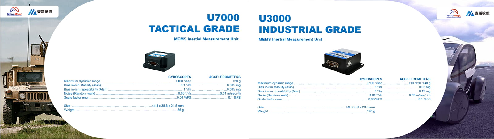
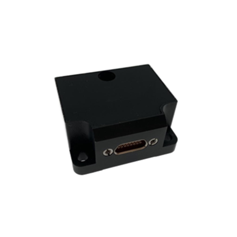
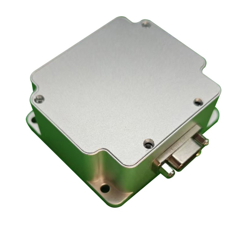
The above article describes the ground positioning method when the IMU and the camera are fixedly installed. It briefly describes the IMU’s high-precision attitude measurement and the camera’s visual positioning capabilities, and can achieve efficient and accurate ground positioning. The MEMS IMU independently developed by Micro-Magic Inc has relatively high accuracy, such as U3000 and U7000, which are more accurate and are navigation-grade products. It can accurately locate and orient. If you want to know more about IMU, please contact our professional technicians as soon as possible.
- MG-502 High Precision MEMS Gyroscope: Precision Navigation in Harsh Drilling Environments
- U6488 high-precision MEMS IMU: the core of stable control for drones and intelligent platforms
- Why the MG-502 MEMS Gyroscope is the “Hidden Eye” of Drone Attitude Control
- Applications of Fiber Optic Gyroscope: Enhancing Navigation and Orientation Precision
- The New Era of High-Precision Positioning: Deep Integration of RTK Technology and the I3700 Dual-Antenna GNSS/INS System
- Understanding Fiber Optic Gyroscope: How It Works
- The influence of low-pressure environment on quartz flexible accelerometers: A key consideration in aerospace applications
- Technical Analysis of Inclinometer Tilt: Accurate Measurement, Stable and Reliable
