




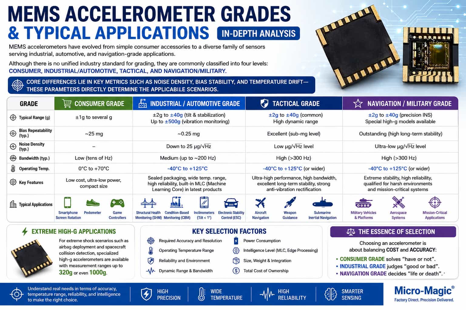
MEMS accelerometers have evolved from early consumer electronics accessories into a diverse family of sensors spanning industrial, automotive, and even navigation-grade applications. In the absence of unified industry-wide standards, they are typically categorized by performance—ranging from low to high—into consumer-grade, industrial/automotive-grade, tactical-grade, and navigation/military-grade. The core differences between these grades lie in key metrics such as noise density, bias stability, and temperature drift; these parameters directly determine their suitability for specific use cases. Consumer-grade accelerometers offer low cost and low power consumption, typically featuring measurement ranges of ±1g to a few g and relatively narrow bandwidths. With poorer bias repeatability (typically around 25mg), they primarily serve motion-sensing applications that do not require high precision, such as smartphone screen rotation, step counting, and game controllers. Industrial and automotive-grade devices offer performance improvements of ten to a hundredfold, with typical bias repeatability reaching 0.25mg and noise density as low as 25μg/√Hz. They cover a wider measurement range—from ±2g for tilt sensing to ±40g for platform stabilization—with some models reaching up to ±500g for vibration monitoring. These devices often utilize hermetic packaging to ensure reliable operation across a wide temperature range of -40°C to +125°C. Typical applications include structural health monitoring (SHM) for bridges and wind turbines, condition-based monitoring (CBM) for factory equipment, inclinometers, and electronic stability control (ESC) systems. Sensors of this grade are essential for applications requiring tilt accuracy better than 1°. The latest industrial-grade products may also incorporate an embedded machine learning core (MLC) to process inference algorithms directly at the sensor level, enabling local decision-making. Tactical and navigation-grade sensors prioritize ultimate performance for use in aircraft navigation, weapon guidance, and submarine inertial navigation systems; they feature bandwidths exceeding 300Hz and must meet extremely rigorous requirements for long-term stability and resistance to vibration rectification effects. Additionally, specialized high-g accelerometers with ranges reaching 320g or even 1000g have emerged for extreme shock scenarios, such as airbag deployment and spacecraft collision detection. Ultimately, selecting an accelerometer involves balancing cost against precision: consumer-grade sensors address basic functionality ("presence vs. absence"), industrial-grade sensors assess quality ("good vs. bad"), and navigation-grade sensors determine mission success or failure ("life vs. death"). Understanding the application's actual requirements regarding precision, temperature range, reliability, and level of intelligence is key to selecting the right model.
Read More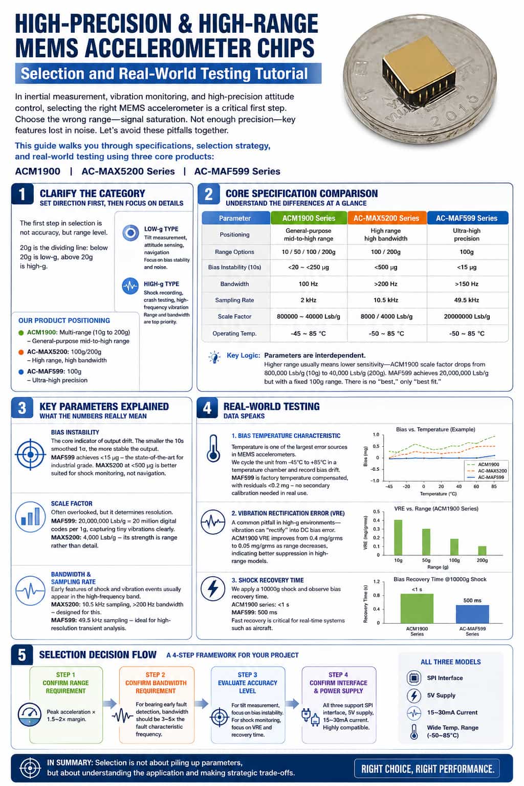
Introduction: In applications such as inertial measurement, vibration monitoring, and high-precision attitude control, selecting the right MEMS accelerometer is often the critical step that determines a system's success or failure. Choosing a range that is too low leads to signal saturation and clipping; insufficient precision causes key features to be drowned out by noise—these are pitfalls many engineers have encountered. Today, using three core products—the ACM1900, AC-MAX5200 series, and AC-MAF599 series—we will guide you through understanding key datasheet specifications and walk you through the entire process from selection to actual testing. This is more than just a lesson on component selection; it is a reusable technical methodology. Part 1: Clarifying Classifications—Set the Direction Before Drilling into Details The first step in selection isn't looking at precision, but at the measurement range class. MEMS accelerometers are typically categorized with 20g as the threshold: ranges below this are "low-g," while those above are "high-g." Low-g types: Used for tilt detection, attitude sensing, and navigation—where bias stability and noise performance are the critical tests. High-g types: Used for shock recording, crash testing, and high-frequency vibration monitoring—where range and bandwidth are the top priorities. Relating this to the three series we are discussing today: · ACM1900: Covers multiple ranges from 10g to 200g; a general-purpose model for medium-to-high ranges. · AC-MAX5200: 100g/200g ranges; high range and high bandwidth, suitable for shock and vibration monitoring. · AC-MAF599: 100g range; ultra-high precision, suitable for inertial navigation and attitude control. Clarifying this positioning ensures the subsequent selection process stays on the right track. Part 2: Comparing Core Specifications—Understanding Differences at a Glance Next, we move to the core technical details: a comparison of the specifications for these three product series. Specifications ACM1900 Series AC-MAX5200 Series AC-MAF599 Orientation General-purpose, medium-to-high range High Range, High Bandwidth Ultra-high precision type Range Options 10/50/100/200 g 100/200g 100 g Bias Stability (10s) <20 to <250 µg <500 µg <15 µg Bandwidth 100 Hz >200 Hz >150 Hz Sampling Rate 2 kHz 10.5 kHz 49.5 kHz Scale Factor 800,000 to 40,000 LSB/g 8000/4000 LSB/g 20,000,000 LSB/g Operating Temperature -45 to 85°C -50 to 85°C -50 to 85°C This chart reveals a fundamental principle: parameters involve trade-offs. A wide measurement range often implies reduced sensitivity—for the ACM1900, as the range increases from 10g to 200g, the scale factor drops from 800,000 to 40,000; conversely, the ultra-high-precision MAF599 boasts a scale factor of 20 million but has a fixed range of 100g. There is no single "best" choice—only the one that best fits the application. Part 3: Key Parameter Analysis—What Do These Numbers Mean? Bias Stability This is a core metric for measuring accelerometer output drift. A lower 1σ value (based on 10-second smoothing) indicates greater output stability. The MAF599 achieves <15 µg, representing the pinnacle of industrial-grade performance. In contrast, the MAX5200 offers <500 µg, making it better suited for shock monitoring than for navigation-grade applications. Scale Factor Often overlooked during selection, this parameter determines resolution. The MAF599’s scale factor of 20 million LSB/g means that 1g of acceleration corresponds to 20 million digital codes, allowing for the clear capture of minute vibrations. The MAX5200, with 4,000 LSB/g, prioritizes a wide measurement range over fine detail resolution. Bandwidth and Sampling Rate Early-stage characteristics of shock and vibration events often manifest in high-frequency ranges. The MAX5200 is specifically designed for this, featuring a 10.5 kHz sampling rate and a bandwidth exceeding 200 Hz. Meanwhile, the MAF599’s 49.5 kHz sampling rate is ideal for transient analysis requiring high temporal resolution. Part 4: Empirical Validation—Letting the Data Speak Once a model is selected, actual testing provides the ultimate verification. We focus on three key dimensions: First, bias temperature characteristics. Temperature is a primary source of error for MEMS accelerometers. During testing, we cycled the devices in a temperature chamber from -45°C to 85°C to record bias drift. The MAF599 undergoes factory temperature compensation, keeping residual error below 0.2 mg; in practical terms, this eliminates the need for secondary calibration. Second, vibration rectification error. This is a common pitfall in high-g environments: vibration itself can be "rectified" into a DC bias error. The ACM1900’s VRE (Vibration Rectification Error) decreases from 0.4 mg/grms to 0.05 mg/grms as the full-scale range increases, indicating that higher-range models offer superior rejection of strong vibrations. Third, consider shock recovery time. Measurements taken after applying a 10,000g shock show the time required for the bias to recover. The recovery time is less than 1 second for the entire ACM1900 series and 500 ms for the MAF599—a critical factor for real-time systems such as those used in aircraft. Part 5: Selection Decision Flowchart Finally, I present a four-step selection decision process that can serve as a reference framework for your project's component selection.
Read More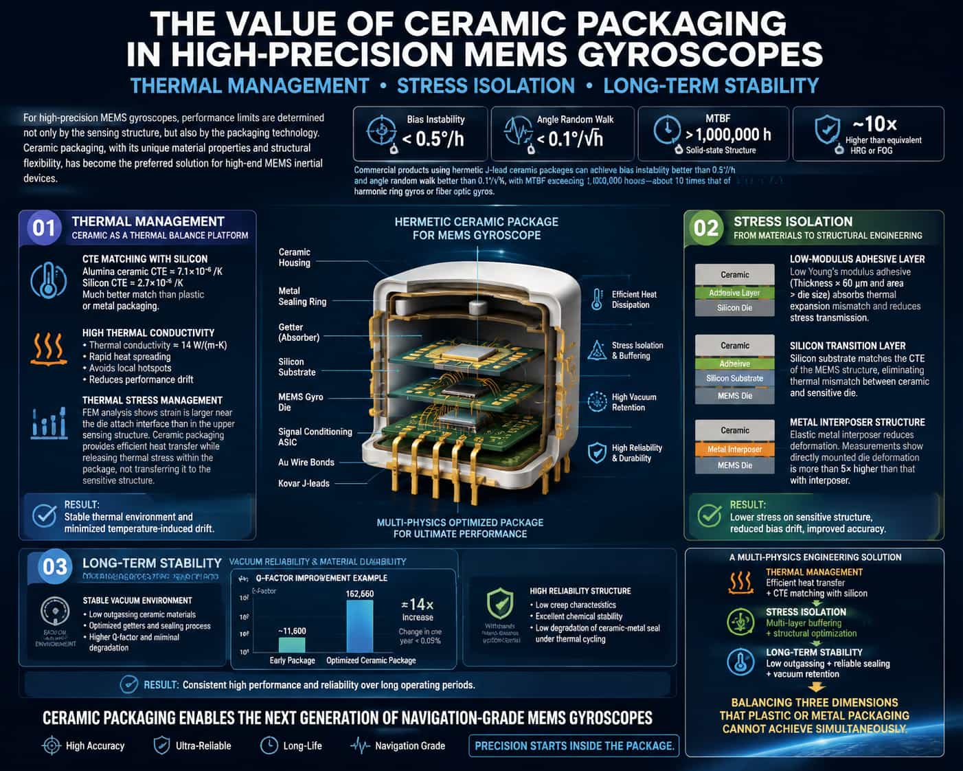
The performance limits of high-precision MEMS gyroscopes are largely determined by their packaging solutions rather than solely by the design of the sensing structure. Thanks to their unique material properties and structural flexibility, ceramic packages have become the preferred choice for high-end MEMS inertial devices. Currently, commercial high-performance MEMS gyroscopes utilizing hermetic J-lead ceramic packages achieve bias stability better than 0.5°/h and angular random walk better than 0.1°/√h. Their solid-state structure yields a mean time between failures (MTBF) exceeding one million hours—up to ten times that of dynamically tuned gyroscopes or fiber-optic gyroscopes with comparable performance. This level of performance is underpinned by the deep optimization of ceramic packaging across three dimensions: thermal management, stress isolation, and long-term stability. Thermal Management: Ceramics as a Thermal Equilibrium Platform The value of ceramic packaging in thermal management is primarily demonstrated by the favorable match between its coefficient of thermal expansion (CTE) and that of silicon. While the CTE of alumina ceramic (approx. 7.1 × 10⁻⁶/K) differs from that of silicon (2.7 × 10⁻⁶/K), the match is significantly better than that offered by plastic or metal packaging. More importantly, the high thermal conductivity of ceramics (approx. 14 W/(m·K)) allows for the rapid dissipation of heat generated by the sensing structure into the external environment, preventing performance drift caused by localized hot spots. Finite element analysis reveals a distinct gradient distribution of stress and strain within the MEMS gyroscope chip: strain in the upper sensing structure is lower than that near the lower bonding interface, and strain in the rigid support pillars and chip edges is lower than in the cavity structure regions. This pattern highlights a critical conflict in thermal management: while packaging materials require high thermal conductivity to achieve thermal equilibrium, the heat conduction path itself can serve as a channel for stress transmission. Ceramic packaging addresses this by facilitating efficient heat conduction while employing structural designs that allow thermal stress to be partially relieved at the package level, rather than being transmitted directly to the sensing structure. Stress Isolation: From Material Selection to Structural Engineering Thermal stress within the package is the primary factor limiting the performance of MEMS gyroscopes. Simulation and experimental studies indicate that the degree of matching between the coefficients of thermal expansion (CTEs) of the ceramic substrate/adhesive and the silicon, as well as the Young's modulus of the adhesive, directly influence the level of thermal stress within the package. Thermal stress can be effectively controlled when the adhesive has a low Young's modulus, the adhesive layer exceeds 60 μm in thickness, and its planar dimensions are larger than those of the chip. The underlying physical mechanism is that the low-modulus adhesive layer acts as a buffer medium; it absorbs the strain energy resulting from thermal expansion mismatch through its own deformation, thereby reducing the stress transmitted to the sensitive structures. More advanced stress isolation strategies involve multi-layer structural designs. The 214th Institute of China North Industries Group Corporation (NORINCO) proposed a low-stress packaging scheme: a silicon substrate is bonded to the bottom of a ceramic package housing, with both the MEMS sensitive structure and signal processing circuitry bonded onto the silicon substrate and electrically connected via gold wire bonding. Serving as a transition layer, the silicon substrate possesses a CTE identical to that of the sensitive structure, thereby eliminating the thermal mismatch issues that would arise from direct contact between the sensitive structure and the ceramic substrate. Building upon this, the use of a localized five-point bonding method—combined with the incorporation of small-diameter glass beads into the adhesive to act as a buffer—can further mitigate thermal stress effects and enhance resistance to high-G loads. International research has also validated similar approaches. By installing an elastic metal interposer within the ceramic chip carrier, the temperature drift of the scale factor and bias in tuning-fork gyroscopes has been significantly suppressed. Holographic interferometry has confirmed that the deformation of a sensitive chip directly brazed to the package is more than five times greater than that of a chip mounted via an interposer. This interposer structure is fabricated from chemically etched metal foil; following gold plating, it is bonded to both the sensor chip and the ceramic package using thermocompression bonding, achieving stress isolation while maintaining mechanical connection stability. Long-term Stability: Vacuum Maintenance and Material Outgassing Control The contribution of ceramic packaging to long-term stability lies primarily in its ability to maintain a vacuum environment over an extended period. The quality factor (Q-value) of a MEMS gyroscope is closely linked to gas damping within the cavity; a decline in the Q-value directly leads to the degradation of bias stability and scale factor stability. Research indicates that the primary cause of Q-value degradation in early vacuum-packaged gyroscopes was the continuous outgassing of residual gases within the cavity. By analyzing the outgassing characteristics of ceramic packages and metal lids using Temperature-Programmed Desorption Mass Spectrometry (TPD-MS)—and subsequently selecting appropriate getters and refining the packaging process—the gyroscope's Q-factor was increased to 162,660. This represents a roughly fourteen-fold improvement over earlier packaging iterations, with a variation of less than 0.05% over the course of a year. These data demonstrate that the long-term stability of the gyroscope is collectively determined by the outgassing rate of the ceramic material itself, the long-term hermeticity of the sealing interface, and the effectiveness of the internal getter. Another advantage of ceramic packaging regarding long-term stability lies in its fatigue resistance. Compared to plastic or metal packaging, ceramic-to-metal sealing interfaces exhibit a slower rate of degradation under thermal cycling conditions. The use of ceramic packaging in the GYPRO4300 enables it to meet the rigorous thermal cycling requirements of critical applications, maintaining high reliability even under harsh conditions involving rapid temperature fluctuations—a testament to the low creep and chemical inertness of ceramic materials. In summary, the value of ceramic packaging for high-precision MEMS gyroscopes cannot be reduced merely to "material selection." It represents a system-level engineering challenge involving multi-physics coupling: thermal management requires the ceramic substrate to possess good thermal conductivity and a Coefficient of Thermal Expansion (CTE) matched to silicon; stress isolation necessitates multi-stage buffer structures, such as low-modulus adhesive layers, silicon interposers, or metal intermediate layers; and long-term stability relies on the comprehensive optimization of ceramic low-outgassing properties, seal durability, and vacuum retention technology. The success of the ceramic packaging solution lies precisely in its ability to strike a balance across these three dimensions—a feat often difficult to achieve simultaneously with plastic or metal packaging. As MEMS gyroscopes advance toward navigation-grade precision, technological innovation at the packaging level will remain a critical pathway for overcoming performance bottlenecks.
Read More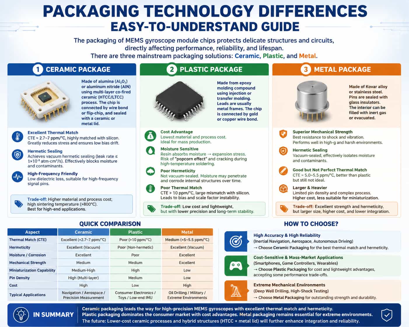
The packaging of MEMS gyroscope module chips refers to the complete process—carried out after wafer-level fabrication of the sensing structure and signal processing circuitry—of enclosing the singulated chip, routing out leads, and establishing electrical interconnections. Packaging directly impacts the module's thermo-mechanical stress environment, hermetic reliability, and signal integrity. Currently, the mainstream packaging solutions for these chips fall into three categories: ceramic, plastic, and metal packaging. Comparison of the Three Packaging Solutions (1) Ceramic Packaging Alumina or aluminum nitride serves as the substrate and housing material. A multi-layer co-fired ceramic process (HTCC/LTCC) is used to fabricate the cavity and interconnect layers; the chip is connected to internal pads via wire bonding or flip-chip bonding and finally sealed with a ceramic or metal lid. Thermal Matching: The Coefficient of Thermal Expansion (CTE) is approximately 6.0–7.2 ppm/°C for alumina and 2.7 ppm/°C for aluminum nitride. These values align closely with silicon, significantly reducing stress exerted on the MEMS structure during temperature fluctuations and ensuring low zero-bias drift. Hermeticity: Capable of achieving a true hermetic seal (leak rate ≤ 1×10⁻⁸ atm·cm³/s), effectively isolating moisture and contaminants, and offering excellent long-term reliability. High Frequency/Low Parasitics: Ceramic materials exhibit low dielectric loss, making them suitable for high-frequency signal pins. The limitations of ceramic packaging include high material and processing costs and high sintering temperatures (>800°C); it is primarily suited for high-end applications. (2) Plastic Packaging The housing is formed using epoxy resin molding compounds via injection or transfer molding processes. Metal lead frames are typically used for pins, and connections between the chip and pins are made via gold or copper wire bonding. Plastic packaging offers significant cost advantages; material and processing costs are substantially lower than those of ceramic or metal packaging, making it suitable for mass production. The disadvantages of plastic packaging are primarily threefold. The CTE of the resin generally exceeds 10 ppm/°C, resulting in significant thermal mismatch with the silicon chip; thermal stress directly causes fluctuations in zero-bias and scale factor. The hydrophilicity of epoxy resin causes swelling stress upon moisture absorption; during high-temperature soldering, this can trigger the "popcorn effect," leading to package cracking. Furthermore, moisture penetration gradually corrodes internal structures, compromising long-term reliability. Additionally, insufficient hermeticity prevents vacuum sealing, making it difficult to meet the long-term stability requirements of high-precision applications. (3) Metal Packaging These packages utilize a housing made of Kovar alloy (an iron-nickel-cobalt alloy) or stainless steel. Leads are insulated and sealed against the metal shell using glass insulators, and the interior can be filled with inert gas or evacuated to a vacuum. Metal packaging is renowned for its exceptional mechanical strength, offering the best shock and vibration resistance among all packaging solutions; it is capable of withstanding extreme operating environments characterized by high overload and high-impact forces. Moreover, its hermeticity rivals that of ceramic packaging, effectively blocking moisture and contaminants to ensure the long-term reliability of the internal chip. The coefficient of thermal expansion (CTE) for metal packaging is approximately 5.0–5.5 ppm/°C; while superior to that of plastic packaging, a mismatch with the silicon die remains, meaning the impact of thermal stress cannot be ignored. Additionally, the package's relatively large size and weight, combined with limited lead density, hinder the development of miniaturized and highly integrated modules. The manufacturing process is complex, and the overall cost can even exceed that of ceramic packaging. Coupled with the industry-wide trend toward miniaturization, metal packaging is gradually being replaced by ceramic packaging solutions in the field of MEMS gyroscopes. Comparative Summary Table Comparison Criteria Ceramic packaging Plastic packaging Metal package Thermal Compatibility (CTE) Excellent (≈2.7–7 ppm/°C) Poor (>10 ppm/°C) Medium (≈5–5.5 ppm/°C) Hermeticity Excellent (vacuum-tight) Poor (non-hermetic) Excellent (vacuum-tight) Moisture/Corrosion Resistance Excellent Poor Excellent Mechanical Strength Medium Medium Excellent Miniaturization Capability Medium-high High Low Lead Density High (supports multi-layer routing) Medium Low Cost High Low High Typical Applications Navigation/Aerospace/Precision measurement Consumer electronics/toys/low-end IMUs Oil drilling / Military / Extreme environments Selection Recommendations · High-precision, high-reliability sectors (inertial navigation, aerospace, autonomous driving): Ceramic packaging is the optimal choice, offering excellent thermal matching and hermeticity. · Consumer electronics and cost-sensitive applications (mobile phones, game controllers, wearable devices): Plastic packaging offers advantages in cost and weight reduction, though it entails some trade-offs in precision. · Extreme mechanical environments (deep-well drilling, high-impact testing): Metal packaging retains a niche market due to its superior mechanical strength. In summary, ceramic packaging—leveraging the dual advantages of thermal matching and hermeticity—represents the mainstream technological approach for high-precision MEMS gyroscope module chips; plastic packaging dominates the consumer market through cost-efficiency; and metal packaging is relegated to specialized environments. Future trends point toward continuous cost reduction in ceramic packaging processes and an evolution toward composite structures—combining high-temperature co-fired ceramics (HTCC) with metal lids—to further enhance integration and reliability, thereby solidifying its core position in high-value applications.
Read More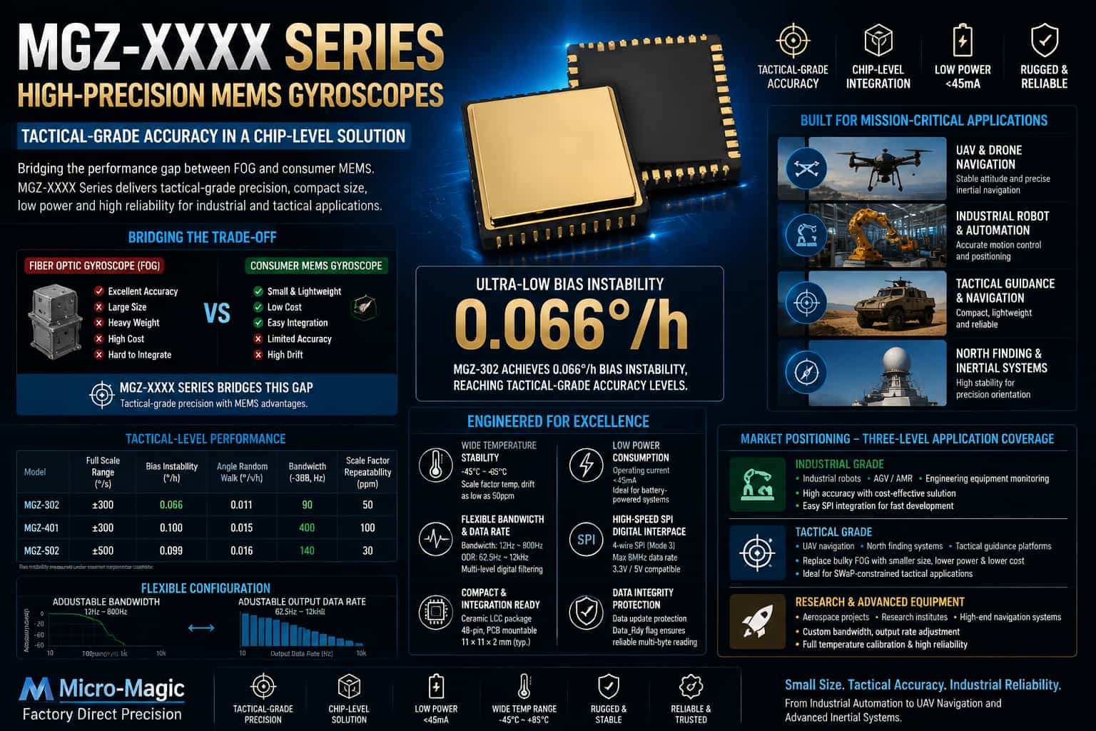
When selecting inertial sensors, engineers often face a dilemma: while fiber-optic gyroscopes meet accuracy requirements, they are bulky, heavy (often weighing hundreds of grams), and expensive (starting at tens of thousands of yuan), making them difficult to integrate into compact platforms like drones and robots. Conversely, while consumer-grade MEMS gyroscopes offer suitable size and cost, their bias stability—typically ranging from several to dozens of degrees per hour—leads to rapid error accumulation in industrial-grade attitude control or tactical-grade navigation scenarios, failing to meet performance standards. Underlying this choice is a long-standing performance gap between these two technological approaches: high-precision solutions are cumbersome and costly, whereas lightweight options lack sufficient accuracy, and there has long been a lack of a chip-level solution capable of effectively balancing both requirements. The MGZ-XXXX series of high-precision MEMS single-axis gyroscope chips was designed specifically to bridge this gap. 1. Product Positioning: Chip-level, Tactical-grade Precision The MGZ-XXXX series is clearly positioned to provide a chip-level solution—suitable for direct integration onto circuit boards—for projects requiring tactical or industrial-grade precision but unable to accommodate the size and cost of fiber-optic gyroscopes. By utilizing high-performance MEMS oscillating structures and low-noise signal chain designs, this series pushes key performance metrics to the threshold of tactical-grade applications. Taking representative models such as the MGZ-302 and MGZ-502 as examples: model Measuring range (°/s) Bias instability (°/h) Angular random walk (°/√h) bandwidth (-3dB, Hz) Scale factor repeatability (ppm) MGZ-302 ±300 0.066 0.011 90 50 MGZ-401 0.1 0.015 400 100 MGZ-502 ±500 0.099 0.016 140 30 Bias instability is a key parameter measuring the magnitude of output drift in a gyroscope under constant temperature conditions. The MGZ-302 achieves a bias instability of 0.066°/h, firmly placing it within the tactical-grade precision range and matching or exceeding the performance of leading international competitors. The MGZ-401 further extends the bandwidth to 400 Hz and reduces group delay to 1.1 ms, enabling the capture of rapid attitude changes in high-frequency dynamic response scenarios. At the same time, this series retains the inherent core advantages of MEMS technology: · Size: Ceramic LCC package with 48 pins, suitable for direct PCB surface mounting. · Power Consumption: Normal operating current <45 mA, making it ideal for battery-powered devices. · Interface: Standard 4-wire SPI digital output (Mode 3 timing) with read/write speeds up to 8 MHz. 2. Core Technical Advantages: From Specifications to Engineering Implementation 2.1. Performance Assurance Across the Full Temperature Range Temperature drift is a primary source of error in the engineering application of MEMS gyroscopes. The MGZ-XXXX series features an integrated 16-bit temperature sensor (register addresses 0x30–0x31) and utilizes factory-calibrated temperature compensation parameters to maintain scale factor stability across a wide temperature range. High-end models achieve scale factor temperature drift as low as 50 ppm, meaning that output scale variations remain within 0.05% across the -45°C to +85°C temperature range. 2.2. Flexible Bandwidth and Filter Configuration Developers can flexibly adjust the output bandwidth (12 Hz–800 Hz) and data refresh rate (62.5 Hz–12 kHz) via registers 0x6F (LPF_BW_CTRL) and 0x6E (ODR). The chip incorporates a configurable three-stage low-pass filter, allowing developers to balance "low latency" against "low noise" based on application requirements—for instance, enabling a single-stage filter minimizes latency, while enabling a three-stage filter minimizes noise. This design enables a single chip to support applications ranging from low-speed attitude monitoring (such as tower tilt detection) to high-speed flight control (such as FPV racing drones). 2.3. Hardware Integration Friendliness and Data Integrity Protection The datasheet provides comprehensive reference circuit designs, PCB layout guidelines, and recommendations for decoupling capacitor selection. The chip supports adaptive 3.3V/5V interface voltage levels and specifies clear power-up sequencing requirements for VCC and VIO, offering substantial benefits in shortening product development cycles and mitigating migration risks. It features a built-in data update protection mechanism: sensor data is first written to a DSP buffer and only refreshed after the old data in the SPI registers has been read. Additionally, a Data_Rdy flag prevents frame misalignment during read operations, ensuring the integrity of multi-byte data transfers. 3. Market Positioning: Adaptation to Three-Stage Application Scenarios Based on accuracy grades and application scenarios, the market positioning of the MGZ-XXXX series is categorized into three tiers: 3.1. Industrial-Grade Applications: Balancing Accuracy and Cost Targeting applications such as industrial robots, AGVs/AMRs, and attitude monitoring for construction machinery, models like the MGZ-201 and MGZ-301 offer bias stability of 0.02–0.03°/h. Their SPI digital output interfaces facilitate direct integration with mainstream MCUs and DSPs. Industry statistics indicate that the demand for high-performance inertial sensors in the fields of industrial automation and intelligent equipment monitoring is growing at an average annual rate of 12%. 3.2. Tactical-Grade Applications: A Key Arena for Precision Replacement of Fiber-Optic Gyroscopes The accuracy specifications of models such as the MGZ-302 and MGZ-401 enable them to cover application scenarios previously dominated by fiber-optic gyroscopes. In tactical-grade applications—such as UAV navigation, missile guidance, and north-finding instruments—where strict constraints exist regarding Size, Weight, and Power (SWaP), MEMS gyroscopes are progressively replacing traditional fiber-optic gyroscopes. The MGZ series stands out as a strong contender for domestic substitution solutions, thanks to its compact ceramic packaging (typical dimensions: 11×11×2 mm), full-temperature-range calibration capabilities, and military-grade reliability screening standards. 3.3. Scientific Research and High-End Equipment: Demands for Customization and High Reliability Catering to university laboratories, research institutes, and aerospace and defense projects, the MGZ series supports customized bandwidth configurations, adjustable output rates, and parameter calibration across the full temperature range, enabling adaptation to the specific requirements of diverse projects. As the market penetration of domestically produced high-precision MEMS inertial sensors continues to rise within the mid-to-high-end sectors, demand in this market segment is growing rapidly.
Read More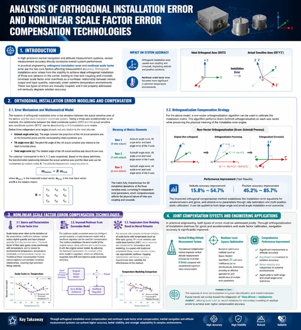
Introduction In high-precision inertial navigation and attitude measurement systems, sensor measurement accuracy directly constrains the system's overall performance. In practical engineering applications, non-orthogonal mounting errors and nonlinear scale errors are the two primary factors affecting measurement accuracy. Non-orthogonal mounting errors arise from the inability to achieve ideal orthogonal mounting of the tri-axial sensors on the carrier, resulting in inter-axis coupling and crosstalk; nonlinear scale errors manifest as a nonlinear relationship between sensor output and input, a phenomenon particularly pronounced in extreme temperature environments. These two types of errors are coupled; if not properly addressed, they can severely degrade the accuracy of the navigation solution. Modeling and Compensation of Non-orthogonal Mounting Errors Error Mechanism and Mathematical Model The essence of non-orthogonal mounting error lies in the deviation between the sensor's actual sensitive axes and the ideal instrument coordinate system. Taking a tri-axial accelerometer as an example, let OXYZ denote the ideal coordinate system and OX′Y′Z′ denote the coordinate system of the actual sensitive axes; the relationship between them can be described by a 3×3 mounting error matrix. To precisely characterize this error, three independent error angles for each actual axis relative to the ideal orientation are defined as follows: (Azimuth error): The angle between the projection of the i-th actual sensitive axis onto the horizontal plane and the direction of the ideal coordinate axis. (Tilt error): The pitch/tilt angle of the i-th actual sensitive axis relative to the ideal horizontal plane. (Torsion error): The rotation angle of the i-th actual sensitive axis about its own axis. Here, the subscript corresponds to the X, Y, and Z axes, respectively. Based on these definitions, the transformation relationship between the actual sensitive axes and the ideal axes can be represented by a rotation matrix R, and the attitude measurement output equation is: The rotation matrix R is: The specific meanings of the elements in the matrix are described as follows: Row 1 (corresponding to the actual X-axis output): represent the azimuth angle error, tilt angle error, and torsion angle error of the X-axis, respectively. Row 2 (corresponding to the actual Y-axis output): represent the azimuth angle error, tilt angle error, and torsion angle error of the Y-axis, respectively. Row 3 (corresponding to the actual Z-axis output):
Read More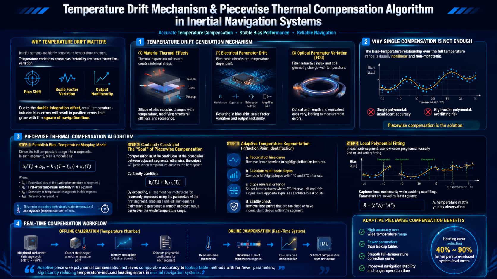
The core components of Inertial Navigation Systems (INS)—gyroscopes and accelerometers—are extremely sensitive to temperature fluctuations. This sensitivity stems from the temperature dependence of material physical properties: variations in the elastic modulus of silicon microstructures; thermal stresses caused by the mismatch in coefficients of thermal expansion (CTE) between silicon and glass in MEMS packaging; changes in optical fiber refractive index and coil geometry in fiber-optic gyroscopes; and temperature-induced drift in reference voltages and amplifier gains within electronic circuits. Temperature drift is particularly critical due to the "double-integration amplification effect": a temperature-induced bias shift, when subjected to the double integration inherent in navigation calculations, results in a positioning error that diverges quadratically with navigation time. Research indicates that the temperature drift coefficient for MEMS accelerometers can reach 0.54 mg/°C, while the bias instability of MEMS gyroscopes over a wide temperature range can reach 4.6°/h—levels that are unacceptable for tactical-grade applications. Drift mechanisms can be categorized into three types: · Thermal effects on materials: CTE mismatch between silicon and packaging materials generates thermal stress, altering the stiffness and resonant frequency of the sensing structure. · Electrical parameter drift: Temperature-induced changes in resistors, capacitors, and reference voltages within the detection circuitry alter the sensor's scale factor and zero-offset. · Optical parameter variations (fiber-optic gyroscopes): Changes in the optical fiber's refractive index, combined with the thermal expansion and contraction of the fiber coil, alter the optical path length and equivalent area. Mathematical Principles of Piecewise Temperature Drift Compensation Algorithms The core task of temperature drift compensation is to establish a mapping model between bias and temperature—that is, to solve for the error function: Here, "bias" represents the zero-offset of the gyroscope or accelerometer, and T denotes temperature. In engineering practice, the function f(T) across the full temperature range often exhibits nonlinear or even non-monotonic characteristics; fitting this range with a single polynomial results in either insufficient accuracy or overfitting due to an excessively high polynomial order. Consequently, the piecewise compensation strategy was developed. Basic form of the piecewise model Divide the entire temperature range into n temperature intervals ; within the j-th interval, the bias is expressed as a function of temperature and its rate of change: Where: is the equivalent bias at the starting temperature point of segment $j$; is the first-order sensitivity coefficient of the bias to temperature within that segment; is the sensitivity coefficient of the bias to the rate of temperature change within that segment; is the reference temperature. This model accounts for both steady-state temperature effects (the second term) and dynamic temperature effects (the third term)—the latter being particularly critical during the warm-up phase following startup. (2) Continuity constraint: the "soul" of piecewise compensation A critical constraint for piecewise compensation is that the compensation values must be continuous at the boundaries between adjacent temperature segments; otherwise, a sudden jump in the output would occur as the temperature slowly crosses the inflection point, leading to discontinuity in the navigation solution. The continuity condition can be expressed as: Upon expansion, the bias of each segment can be expressed recursively in terms of the parameters of the first segment; this allows the fitting parameters for all segments to be treated as a unified whole for least-squares estimation, thereby ensuring the smoothness and continuity of the curve across the entire temperature range. (3) Inflection Point Identification and Adaptive Segmentation Segmentation hinges on identifying inflection points—temperature nodes where the slope of the temperature-bias curve changes significantly. An adaptive inflection point identification algorithm is employed in engineering practice, with the following core logic: a. Reconstruct the bias curve: Subtract the linear baseline (calculated over the full temperature range) from the raw bias data to accentuate the characteristics of the inflection points. b. Calculate multi-scale slopes: Compute the left and right slopes at intervals of 1°C and 5°C, respectively. c. Slope sign criterion: Identify temperature points where the signs of the left and right slopes (at the 5°C interval) differ; designate these as candidate inflection points. d. Validity check: Eliminate "pseudo-inflection points" that are spaced too closely or lack sufficient slope consistency within the interval. Once inflection points are identified, low-order polynomial fitting (typically second or third-order) is applied within each sub-interval; this approach captures local nonlinearity while avoiding overfitting. The fitting parameters are determined using the least-squares method: Here, Temp is the temperature matrix, and B represents the corresponding bias observations. Real-time compensation process In actual engineering implementation, segmented temperature drift compensation is divided into two stages: · Offline calibration stage: The IMU is placed in a thermostat to perform temperature cycles across the full temperature range (such as -30°C to 70°C), record the static output at each temperature point, and complete inflection point identification and calculation of fitting parameters for each segment. · Online compensation stage: The system reads the temperature sensor value in real time, determines the range to which the current temperature belongs, substitutes it into the corresponding model to calculate the compensation amount, and deducts it from the original output: Research indicates that the adaptive piecewise polynomial method can achieve compensation accuracy comparable to that of the look-up table method while requiring significantly fewer compensation parameters. Regarding system-level heading effect errors caused by temperature fluctuations, a compensation method based on the Fourier expansion of temperature variations can reduce the error by 40% to 90%.
Read More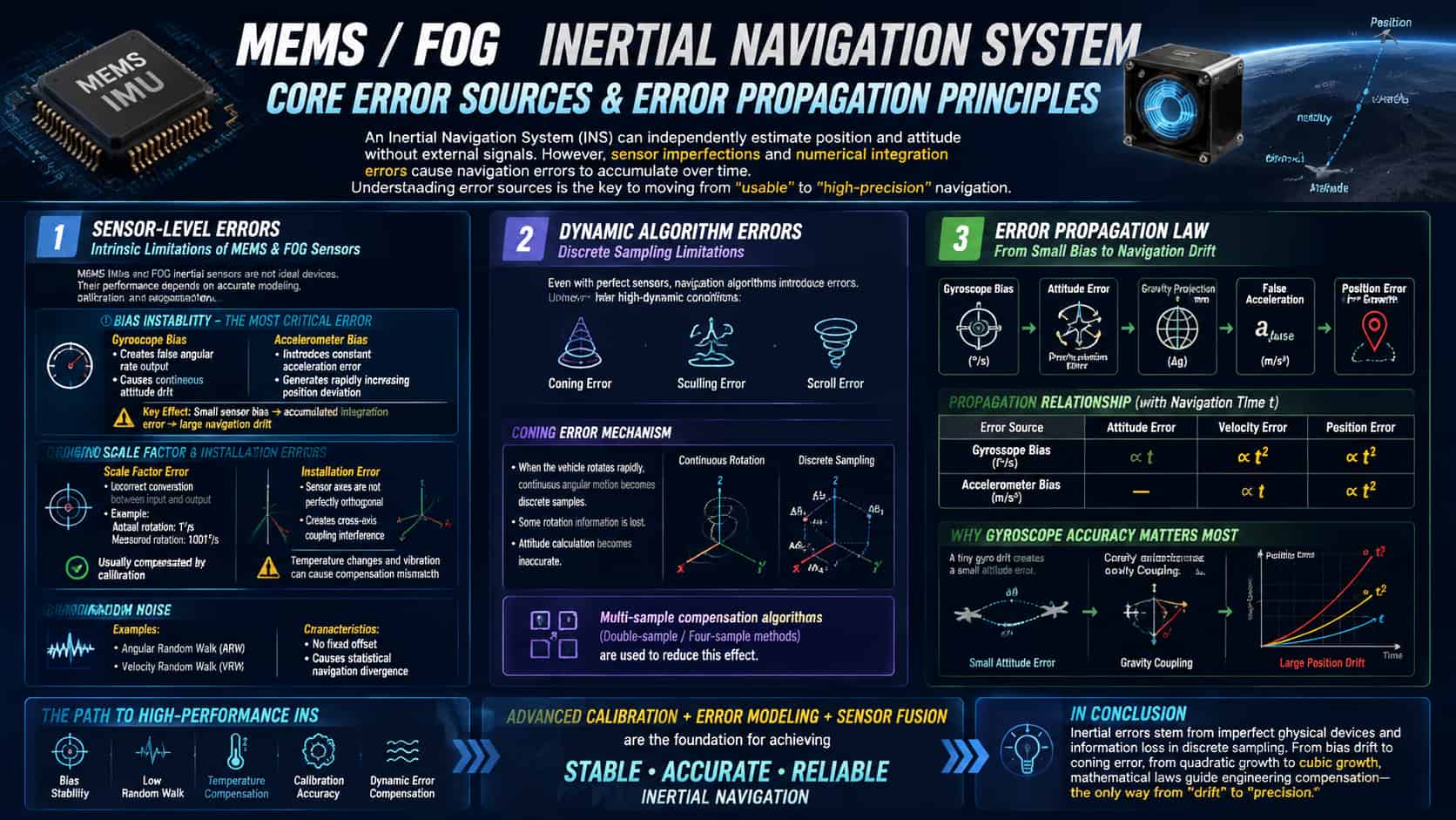
The allure of inertial navigation systems lies in their ability to autonomously calculate position and orientation without relying on any external signals. The trade-off, however, is that errors accumulate relentlessly over time. Understanding the primary sources of these errors is a crucial step in transitioning from a system that merely "works" to one that performs exceptionally well. 1. Sensor-Level Errors: The "Inherent Flaws" of the Hardware The core components of an inertial navigation system (INS)—gyroscopes and accelerometers—are not ideal sensors. Error analysis begins with modeling and quantifying these "inherent flaws." Bias is one of the most critical sources of error. A gyroscope's output of a false angular rate while stationary leads to continuous orientation drift, while an accelerometer's bias introduces a constant offset directly into specific force measurements. An accelerometer bias of just 0.1 mg can result in a positional error of approximately 50 meters within 100 seconds. The danger of bias lies not only in the offset itself but in its amplification through double integration: positional error grows in proportion to the square of time. Scale factor errors and installation errors are classified as structural errors. An inaccurate scale factor means, for instance, misinterpreting a rotation of 1°/s as 1.001°/s; installation errors result in the three sensitive axes not being perfectly orthogonal, creating cross-coupling interference. While such errors can usually be compensated for via factory calibration, temperature fluctuations and mechanical shocks can cause the compensation parameters to become mismatched. From a dynamic perspective, the angular motion of the mounting base introduces additional error terms in the gyroscope and accelerometer outputs—coupled with angular velocity and angular acceleration—that are significant enough to warrant attention. Random noise (such as angle random walk and velocity random walk), while not producing a constant offset, causes navigation errors to exhibit characteristics of statistical, random divergence. 2. Algorithm-Level Dynamic Errors: The Pitfalls of Discrete Sampling Even with perfect sensors, the numerical integration process itself introduces errors. In high-dynamic environments—characterized by factors such as high-frequency vibration and violent maneuvers—classic errors known as "coning error," "sculling error," and "scrolling error" arise. Take coning error as an example: when the angular velocity vector of the vehicle rotates rapidly in space, discrete sampling captures angular increments only at specific, finite moments. Consequently, the continuous trajectory of the rotation vector cannot be precisely reconstructed, resulting in a loss of rotational information. Multi-sample coning compensation algorithms (such as two-sample or four-sample schemes) are specifically designed to mitigate this loss of information. 3. Error Propagation: The Mathematical Progression from "Differential" to "Divergence" The fundamental error propagation characteristics of inertial navigation systems can be summarized as follows: attitude errors caused by gyroscope bias grow linearly with navigation time, velocity errors grow quadratically, and position errors grow cubically; meanwhile, velocity errors caused by accelerometer bias grow linearly with navigation time, and position errors grow quadratically. Starting from basic kinematic relationships: ideally, position is determined by the double integration of specific force: Considering a constant accelerometer bias δα (where the measured value is f̃ = f + δα), the position calculation error δr(t) is: This relationship reveals the most critical characteristic of inertial navigation errors: quadratic divergence. To illustrate with a concrete numerical example: an accelerometer bias of just 0.01 m/s² (approximately one-thousandth of the acceleration due to gravity) can result in a position error of about 50 meters within 100 seconds. The impact of gyroscope bias is even more profound. Let ε (rad/s) be the constant drift rate of the gyroscope; this directly causes the attitude error δϕ to grow linearly over time: A ttitude error causes a deviation in the gravity vector during calculation, introducing spurious acceleration; after double integration, the resulting position error is ultimately proportional to the cube of time. This is the fundamental reason why gyroscope precision is critical: under gravity coupling, minute attitude deviations are amplified into position errors that diverge cubically. The complete error propagation is typically expressed in state-space form: This equation provides a basis for correction for integrated navigation algorithms, such as the Kalman filter. Conclusion Inertial navigation errors stem from physical hardware imperfections and the loss of information inherent in discrete sampling. From bias drift to coning errors, and from quadratic to cubic divergence, the principles revealed by mathematical formulas point the way toward engineering-based compensation—marking the essential path for inertial navigation systems to evolve from "drifting" to "precise."
Read More
For a long time, procurement channels for high-end MEMS IMUs have been severely limited; users were forced to choose from a handful of international suppliers, accepting standardized off-the-shelf products, enduring long lead times, and paying premium prices. The emergence of localized supply solutions is transforming this landscape. Beyond matching performance benchmarks, domestic IMU suppliers offer differentiated value across four key dimensions, profoundly influencing procurement decisions in the industrial, robotics, and autonomous systems markets. **Cost: From High Premiums to Economic Viability** Cost is the primary driver of supply diversification. The high-end IMU market has long been characterized by concentrated supply and rigid pricing. Domestic suppliers derive their cost advantages from three levels: In manufacturing, advanced processes—such as wafer-level packaging—have significantly improved yields, effectively amortizing the manufacturing cost per chip. Regarding calibration efficiency, fully automated lines utilize batch parallel testing, drastically reducing the time and equipment costs associated with traditional item-by-item calibration. In terms of the supply chain, localizing the entire value chain—from chip design to packaging and testing—minimizes intermediaries, logistics costs, and tariffs. At scale, domestic products can be priced at 50% to 70% of comparable imports, reducing the overall Bill of Materials (BOM) cost by 30% to 60%. For end-users, this translates to superior procurement costs for equivalent performance, as well as a more predictable long-term cost structure. **Delivery: From Months of Waiting to Flexible Scheduling** Long lead times for imported IMUs have long been a pain point. Delivery for high-end MEMS IMUs often takes weeks or even months from the time of order. Global supply chain fluctuations can further extend these timelines or even cause disruptions. The delivery advantages of localized supply manifest in two ways: regarding production capacity, multiple fully automated calibration lines have been established domestically, ensuring capacity planning remains unaffected by the international trade environment. In terms of responsiveness, domestic manufacturers can shorten sample delivery times to just a few days. From component selection and design to debugging and validation, local technical support teams provide full-lifecycle assistance—spanning R&D to mass production—thereby significantly accelerating time-to-market. For development projects with tight schedules, these delivery advantages are often more compelling than price alone. Customization: From Standardization to On-Demand Configuration Imported IMUs are primarily standardized, off-the-shelf products, forcing users to accept fixed specifications. Domestic suppliers have broken this limitation by offering greater customization flexibility: at the hardware level, dimensions, mounting methods, connector types, and supply voltages can be tailored; at the software level, communication protocols, data output formats, and register mappings can be customized; and regarding performance, parameters such as measurement ranges, filtering bandwidths, calibration temperature ranges, and even proprietary error compensation models can be optimized for specific application scenarios. This flexibility is particularly crucial for two types of users: those needing to retrofit existing systems, where customization minimizes system modifications; and those operating under unique conditions, where customization maximizes performance for specific scenarios. Support: From Technical Documentation to System Empowerment In the context of global competition, technical support capabilities are defined not merely by response speed, but by the construction of a technical ecosystem that deeply empowers the user. Regarding comprehensive and internationalized documentation, domestic suppliers provide complete data sheets, application notes, reference designs, and integration guides based on real-world cases in both Chinese and English, ensuring that engineers worldwide can efficiently handle component selection and design. In terms of an open technical ecosystem, domestic suppliers typically provide fully open register manuals, communication protocol stack source code, and calibration toolchains, allowing users to exercise deep control over product behavior without relying on a vendor's closed APIs. This openness offers a distinct value proposition often lacking in imported products, making it particularly suitable for R&D teams with deep system customization needs. Regarding professional support teams, engineers with extensive industry experience assist users with precise selection and solution evaluation during the pre-sales phase, and help resolve complex issues—such as hardware-software integration and data fusion—during the R&D phase. This professional collaboration effectively reduces system integration risks for users and shortens time-to-market. For demanding industrial-grade and automotive-grade applications, comprehensive technical documentation, an open technical ecosystem, and professional technical collaboration collectively ensure high-quality delivery. Conclusion Cost, delivery, customization, and support—these four advantages form a complete value loop: cost advantages lower procurement barriers, delivery advantages ensure project schedules, customization advantages meet differentiated needs, and support advantages eliminate technical obstacles.
Read More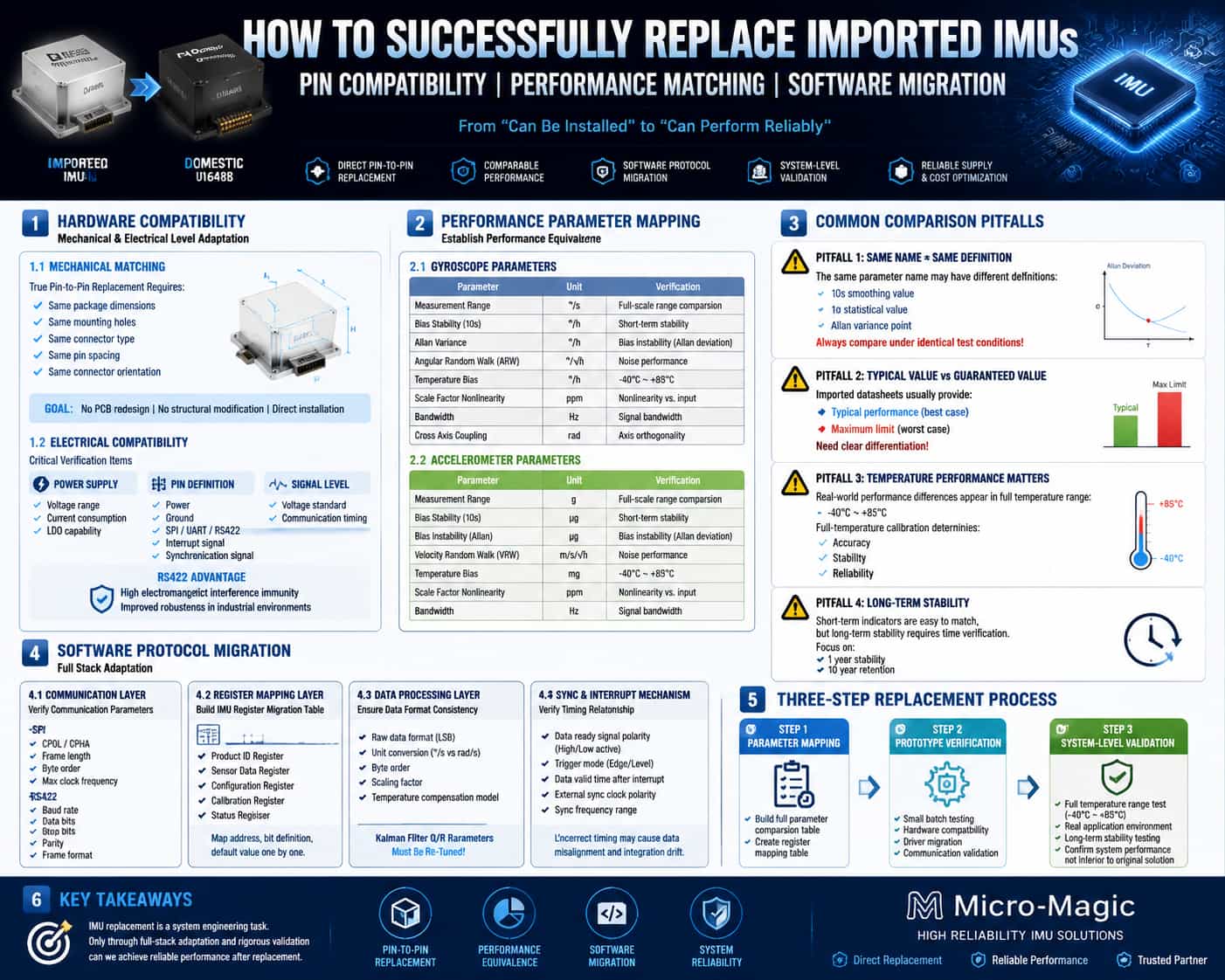
1. Introduction Replacing an Inertial Measurement Unit (IMU) is far more complex than simply swapping out a chip. IMU replacement entails system-level adaptation across multiple layers, including mechanical mounting, electrical connections, communication protocols, register mapping, and data processing pipelines. This article systematically outlines the practical steps and technical considerations involved in the IMU replacement process, focusing on three dimensions: hardware pin compatibility, performance parameter benchmarking, and software protocol migration. 2. Pin Compatibility: Mechanical and Electrical Adaptation 2.1. Mechanical Dimensions and Mounting Interfaces The first level of pin compatibility is mechanical compatibility. High-end IMUs often utilize modular packaging; physical dimensions, mounting hole locations, and connector types directly determine the feasibility of a "drop-in replacement." To achieve replacement without modifying the PCB or housing, these mechanical parameters must match on a 1:1 basis. In practice, key factors to verify include: module dimensions (length, width, height), mounting hole diameters and positions, connector models and pin pitch, and connector orientation and locking mechanisms. While some replacement products feature optimized dimensions beneficial for new designs, these changes can create mounting issues for drop-in replacements in existing systems, potentially necessitating the design of adapter brackets. 2.2. Electrical Pin Definitions and Signal Levels Following mechanical compatibility comes electrical compatibility. Core verification items include: supply voltage and power consumption, pin function definitions (power, ground, communication interfaces, interrupt/synchronization signals), and signal level standards. Taking the SPI interface as an example, some replacement products utilize RS-422 differential interfaces. RS-422 offers common-mode noise rejection exceeding 80 dB—an improvement of 30–40 dB over single-ended signals—which is crucial for system robustness in high-EMI environments (such as industrial motor drives). However, converting between RS-422 and SPI involves redesigning the protocol layer; it is not merely a matter of changing a few wires. 2.3. Power Supply and Timing Considerations Power-up timing and power consumption differences are the most frequently overlooked aspects of pin compatibility. If the replacement product consumes more power than the original, the load capacity of the existing power supply's LDO (Low-Dropout Regulator) must be verified. Differences in power-up initialization timing are also critical; some substitute products may require a longer stabilization time upon power-up, necessitating an added delay in the host controller before data reading begins. Additionally, some modules exhibit pulse noise at the moment of power-up, requiring the addition of filtering capacitors at the power supply input. 3. Parameter Benchmarking: Precise Mapping of Performance Metrics 3.1. Key Dimensions for Parameter Benchmarking The essence of parameter benchmarking is establishing a "performance equivalence relationship" between the substitute product and the original product. Key benchmarking dimensions include: Gyroscope: Measurement range (°/s), bias stability (°/h), bias instability (°/h, Allan variance), angular random walk (°/√h), full-temperature bias (°/h), scale factor nonlinearity (ppm), bandwidth (Hz), and cross-coupling (rad). Accelerometer: Measurement range (g), bias stability (μg), bias instability (μg, Allan variance), velocity random walk (m/s/√h), full-temperature bias (mg), scale factor nonlinearity (ppm), and bandwidth (Hz). 3.2. Key Pitfalls in Benchmarking Pitfall 1: Differing metric definitions. While all may be labeled "bias stability," some manufacturers use a 10-second smoothed value, others use a 1σ statistical value, and some use the inflection point value from the Allan variance plot. Comparisons must be made under identical testing conditions. Pitfall 2: Typical values vs. maximum values. Datasheets for imported products often list both typical and maximum values, whereas substitute products might only specify an upper limit (≤). It is essential to distinguish between "typical performance" and "guaranteed performance" during benchmarking. Pitfall 3: Overlooking full-temperature performance. Benchmarking parameters at room temperature is relatively straightforward; the true performance gap often manifests across the full operating temperature range (-40°C to 85°C). Imported products benefit from factory calibration covering the entire temperature range, a key factor in their superior performance. If substitute products are calibrated only at room temperature, their performance may degrade significantly under extreme temperatures. Pitfall 4: Long-term stability. Short-term metrics found in datasheets are easy to benchmark, but long-term metrics—such as stability over one year or retention over ten years—require time to verify. This represents the most difficult "engineering maturity barrier" for substitute products to overcome. 4. Software Protocol Porting: Full-Stack Adaptation from Physical to Application Layers Software porting is the most complex and frequently underestimated aspect of IMU replacement. Even if pinouts and parameters are perfectly matched, the system will fail to operate if the software layers are incompatible. 4.1. Communication Protocol Layer First, the communication interface type—SPI, I2C, UART, or RS422—and its specific parameters must be verified. Taking SPI as an example, parameters to check include clock polarity (CPOL) and clock phase (CPHA), frame length (8/16/32-bit), data byte order (big-endian/little-endian), and maximum clock frequency. In SPI communication, the "inter-transfer delay"—the minimum interval between two SPI commands—must be handled correctly to avoid data read failures. For RS422, parameters such as baud rate, data bits, stop bits, parity bits, and frame format require verification. 4.2. Register Mapping Layer This is the core challenge of software porting. It is virtually impossible for IMUs from different manufacturers to align perfectly regarding register address allocation, data formats, and control bit definitions. Key register categories requiring porting include: product identification registers (for verifying the communication link), sensor data registers (addresses and bit widths may differ), configuration registers (measurement range, filtering, sampling rate), calibration registers (addresses for bias and scale factor correction), and status registers (bit definitions for error flags and data-ready flags). In practice, a "register mapping table" should be created to map the address, bit definitions, and default values of each key register from the original product to the replacement product. For functions that do not exist in the replacement, adaptations must be made at the driver layer, or relevant calls must be removed. 4.3. Data Processing Layer Differences may exist in the raw output format of sensor data (LSB vs. physical units), units of measurement (°/s vs. rad/s), byte order, and scaling factors. If the replacement product outputs physical quantities directly while the original product outputs raw LSB values, a unit conversion interface must be added to the driver layer. Error compensation models may also differ; for instance, imported products might feature built-in first-order polynomial compensation, whereas the replacement product might support higher-order temperature compensation models, necessitating an expansion of the compensation interface. The Q and R noise matrices for the Kalman filter must be recalibrated based on the stochastic walk characteristics of the replacement product; the original parameters cannot be reused directly. 4.4. Synchronization and Interrupt Mechanisms Parameters such as the polarity (active high/low), trigger mode (edge/level), and timing relationship (latency between the data-ready signal and valid data) of the data-ready signal may vary. The polarity and frequency range of the external synchronization clock must also be verified. Improper handling can lead to timing mismatches in data acquisition and cumulative errors in attitude estimation. 5. Conclusion IMU replacement is a systematic engineering task, far more complex than a simple "pin-to-pin" component swap. At the hardware level, full compatibility regarding mechanical dimensions, pin assignments, and power-up sequencing must be verified. At the parameter level, a point-by-point comparison under identical test conditions is required, with particular attention paid to performance across the full temperature range and long-term stability. At the software level, full-stack adaptation is necessary, covering everything from communication protocols and register mapping to data processing pipelines. In practice, a "three-step" strategy is recommended: first, establish a comprehensive parameter comparison list and register mapping table; second, conduct hardware compatibility verification and driver porting using a small batch of samples; and third, perform system-level performance validation across the full temperature range and under actual operating conditions to confirm that the system's overall performance with the replacement component is not inferior to the original solution. Only through this process can one successfully transition from merely "fitting the part" to achieving "optimal system performance."
Read More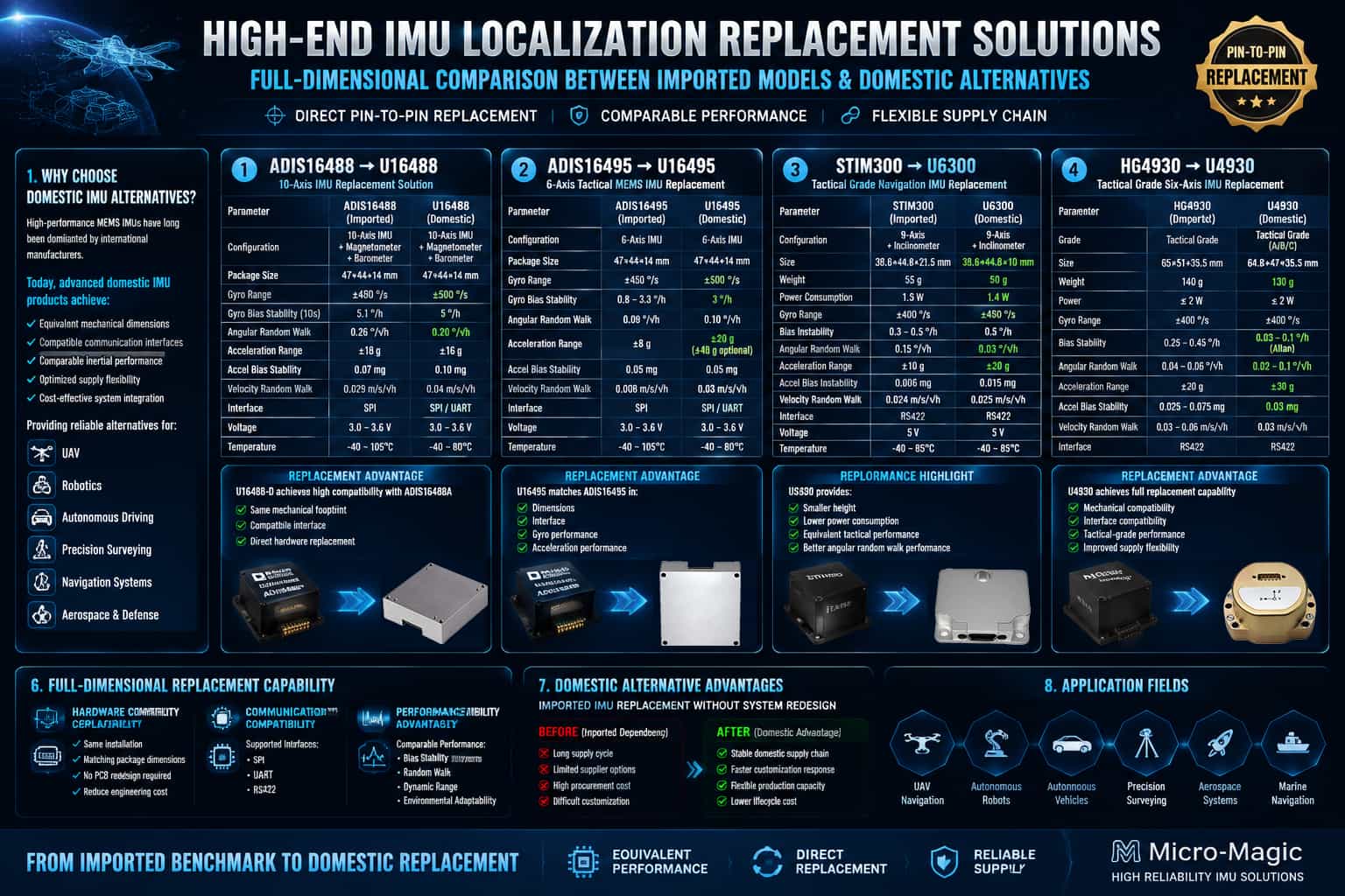
1. Overview Inertial Measurement Units (IMUs) are core sensors in fields such as drones, robotics, autonomous driving, and precision surveying. For a long time, the market for high-end MEMS IMUs was dominated by a few overseas manufacturers. In recent years, however, various domestic products have successfully matched mainstream international models in terms of performance specifications, package dimensions, and interface protocols, offering end-users more diverse supply chain options. This article selects four sets of representative benchmark models—ADIS16488 vs. U16488, ADIS16495 vs. U16495, STIM300 vs. U6300, and HG4930 vs. U4930—and conducts a comprehensive side-by-side comparison of their parameters, covering aspects such as gyroscopes, accelerometers, physical characteristics, and environmental adaptability. 2. Overview of Key Parameter Comparisons 2.1. ADIS16488 vs. U16488 Model ADIS16488 (Imported) U16488 (Domestic) Type 10-axis (+ magnetometer + barometer) 10-axis (+ magnetometer + barometer) Package (mm) 47 × 44 × 14 47 × 44 × 14 (drop-in replacement) Gyro Range (°/s) ±450 ±500 Gyro Bias Instability (°/h) 5.1 0.8 Gyro Angular Random Walk (°/√h) 0.26 0.2 Accelerometer Range (g) ±18 ±16 Accelerometer Bias Instability (mg) 0.07 0.03 Accelerometer Velocity Random Walk (m/s/√h) 0.029 0.04 Interface SPI SPI/UART Operating Voltage 3V ~ 3.6V 3V ~ 3.6V Operating Temperature -40°C ~ 105°C -40°C ~ 80°C Benchmarking Conclusion: The U16488 is fully compatible with the ADIS16488 in terms of package dimensions, pin assignments, and SPI interface, enabling seamless drop-in replacement. Its gyro bias instability outperforms the imported model by an order of magnitude, significantly enhancing the long-term stability of attitude estimation. Although its maximum operating temperature is slightly lower, it is perfectly suitable for standard industrial and UAV applications, offering distinct advantages in overall cost-performance and supply stability. 2.2. ADIS16495 vs. U16495 Model ADIS16495 (Imported) U16495 (Domestic) Type 6-axis 6-axis Package (mm) 47 × 44 × 14 47 × 44 × 14 (Drop-in replacement) Gyro Range (°/s) ±450 ±500 Gyro Bias Instability (°/h) 0.8 – 3.3 0.3 Gyro Angular Random Walk (°/√h) 0.09 0.1 Accelerometer Range (g) ±8g ±20g (±40g optional) Accelerometer Bias Instability (mg) 0.05mg 0.01mg Accelerometer Velocity Random Walk (m/s/√h) 0.008 0.03 Interface SPI SPI/UART Operating Voltage 3V – 3.6V 3V ~ 3.6V Operating Temperature −40°C – 105°C -40°C ~ 80°C Benchmarking Conclusion: The U16495 is fully compatible with the ADIS16495 in terms of mechanical dimensions and electrical interfaces, allowing for direct replacement without hardware modifications. It features a gyro bias instability as low as 0.3°/h and an extended accelerometer measurement range (±20g, with an optional ±40g), making it suitable for high-dynamic applications. With overall performance matching or exceeding that of the original product, it serves as a reliable domestic alternative for high-end navigation and control systems. 2.3. STIM300 vs U6300 Model STIM300 (Imported) U6300 (Domestic) Type 9-axis (+ inclinometer) 9-axis (+ inclinometer) Dimensions/Weight 38.6×44.8×21.5mm /55g 38.6×44.8×10mm / 50g Power Consumption 1.5W 1.4W Gyroscope Range (°/s) ±400 ±450 Gyroscope Bias Instability (°/h) 0.3 - 0.5 0.1 - 0.5 Gyroscope Angular Random Walk (°/√h) 0.15 0.03 Accelerometer Range (g) ±10 ±20 Accelerometer Bias Instability (mg) 0.006 0.01 Accelerometer Velocity Random Walk (m/s/√h) 0.024 0.02 Interface RS422 RS422 Operating Voltage 5V 5V Operating Temperature −40°C ~ 85°C −40°C ~ 85°C Benchmarking Conclusion: While being thinner and lighter, the U6300 matches the STIM300 in RS422 interface and power supply specifications, ensuring easy replacement. Its angular random walk (0.03°/√h) is significantly superior to the imported product, and it exhibits lower angular measurement noise, making it particularly well-suited for high-precision pointing and stabilization control tasks. It offers a matching full-temperature operating range and comprehensive performance parity, with certain specifications actually surpassing the benchmark. 2.4. HG4930 vs U4930 Model HG4930 (Imported) U4930 (Domestic) Type Tactical-grade six-axis Tactical-grade 6-axis (A/B/C settings) Dimensions/Weight 65 x 51 x 35.5mm/140g
Read More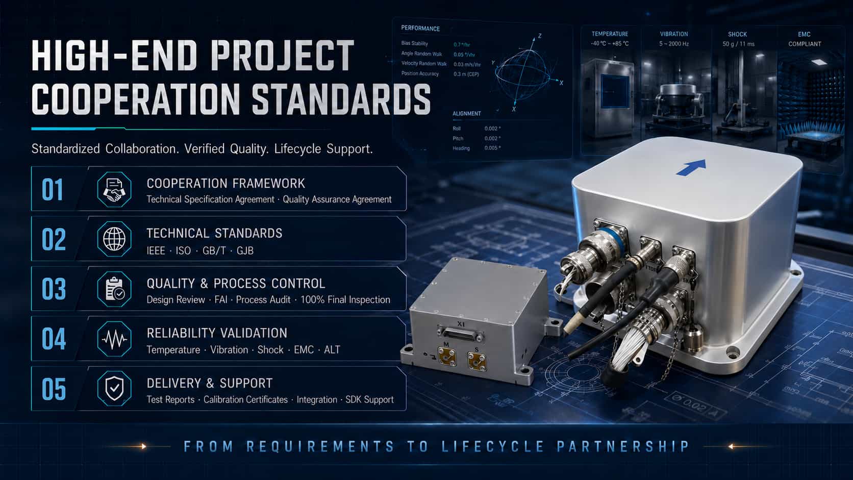
Inertial sensors—including accelerometers, gyroscopes, and inertial measurement units (IMUs)—are core components of aviation navigation, guidance, and control systems; their performance and reliability directly determine flight safety and mission success. Projects involving inertial sensors in the aviation sector entail full lifecycle management, ranging from qualification and certification, delivery and acceptance, and custom R&D to technical support. This article provides a technical analysis of these four dimensions, drawing upon international standard systems and engineering practices. 1. Aviation Project Qualification To enter the airworthy market, aviation inertial sensors must undergo a series of rigorous qualification and certification processes. These cover multiple aspects, including hardware environmental adaptability, software safety, hardware design assurance, and technical standard verification. Environmental Adaptability Certification: RTCA DO-160, *Environmental Conditions and Test Procedures for Airborne Equipment*, is the core standard for environmental testing of avionics hardware and is recognized by the International Organization for Standardization (ISO) as the de facto international standard ISO-7137. This standard defines minimum environmental test conditions and procedures for a full range of airborne equipment, spanning everything from light general aviation aircraft and helicopters to large jetliners and supersonic aircraft. DO-160 encompasses over 20 tests, including temperature, vibration, shock, humidity, altitude, waterproofing and dustproofing, salt fog and fungus resistance, electromagnetic compatibility (EMI/EMS), lightning effects, electrostatic discharge, and power input and voltage transients. Software and Hardware Certification: DO-178, *Software Considerations in Airborne Systems and Equipment Certification*, is the gold standard for aviation software safety certification. It categorizes software into assurance levels ranging from A to E, with Level A applying to the most critical flight safety functions. DO-254, *Design Assurance Guidance for Airborne Electronic Hardware*, addresses design assurance for complex electronic hardware. Certification for inertial navigation products typically requires software to meet DO-178B/C Level A standards and hardware to meet DO-254 Level A standards. Technical Standard Order (TSO): A TSO is a minimum performance standard issued by the U.S. Federal Aviation Administration (FAA); manufacturers must obtain TSO Authorization (TSOA) before their equipment can be installed on certified aircraft. TSOs related to inertial navigation systems include TSO-C4c (Gyroscopes), TSO-C5f (Attitude and Heading Reference Systems), TSO-C6e (Directional Gyros), TSO-C88b (Autopilots), and TSO-C201 (AHRS), among others. GJB References: Qualification for Chinese military inertial sensor projects is primarily based on the GJB 9001C quality management system, the qualification review for equipment manufacturing units, and the GJB 150 series of environmental test standards; technically, these share a common lineage with MIL-STD and DO series standards. 2. Delivery Specifications Delivery specifications for inertial sensors cover product inspection, acceptance criteria, packaging and transportation, and documentation delivery, ensuring quality control and traceability throughout the entire process from factory departure to aircraft installation. Inspection and Acceptance: Delivery inspections for aviation-grade inertial sensors are categorized into factory inspection (full-parameter performance testing and full-temperature calibration), acceptance inspection (re-testing upon arrival), and qualification inspection (type-certification testing). Specifications for airborne inertial navigation systems cover technical requirements, test methods, inspection rules, and packaging/transportation; specifications for civil UAV IMUs detail classification levels and maintenance requirements. Packaging and Transportation: Packaging for military inertial navigation equipment follows MIL-STD-2073-1 (Military Level B individual packaging), specifying methods to prevent corrosion and mechanical damage to ensure integrity during storage and multiple transport cycles; marking complies with MIL-STD-129. Civil aviation applications refer to DO-160 and related specifications, outlining specific requirements for moisture, shock, and electrostatic protection. Documentation Delivery: Deliverables typically include product specifications, test reports (environmental testing, electromagnetic compatibility, life testing, etc.), calibration certificates, Declarations of Conformity (DoC), user manuals, and maintenance manuals. For products certified under DO-178/DO-254, a complete software/hardware design assurance data package is also required. 3. Custom Development Aviation applications often demand highly customized inertial sensors; different platforms (fixed-wing aircraft, rotorcraft, UAVs) and mission profiles (civil aviation, military, scientific research) impose varying requirements regarding accuracy, size, weight, power consumption (SWaP), interface protocols, and environmental adaptability. Hardware Customization: Custom development encompasses sensor selection and configuration (choosing between technologies such as MEMS, fiber-optic, or laser gyros), customization of form factors and mechanical interfaces (e.g., modifying the housing to fit specific installation spaces), connector selection (e.g., MIL-Spec 38999 filtered connectors), and design enhancements for environmental resilience (vibration and shock resistance, wide operating temperature range). Software and Algorithm Customization: This includes the customization of communication protocols (RS-232/422/485, ARINC, CAN, etc.), configuration of data output formats and rates, optimization of sensor fusion algorithms, and programming for lever-arm effects and mounting orientation. Some suppliers also offer custom development of non-standard testing systems and specialized software tools. Customization Process: A typical custom development workflow involves requirements analysis, solution design, prototype fabrication, environmental verification (e.g., DO-160 testing), system integration, and flight testing. Many suppliers possess end-to-end in-house manufacturing capabilities—ranging from MEMS wafer fabrication to IMU calibration—ensuring quality control for customized products. 4. Technical Support Technical support is a crucial component of the full lifecycle service for inertial sensors, covering the entire chain from selection consultation and system integration to on-site commissioning, fault diagnosis, and maintenance/calibration. Selection and Integration Support: Suppliers typically provide evaluation kits to help customers verify performance during the early stages of a project. Technical teams assist customers throughout the process—from sensor selection and interface matching to system integration—resolving engineering challenges such as data fusion, coordinate system transformation, and error compensation. Some manufacturers offer 24/7 technical support covering the entire workflow, from selection and integration to data fusion. Calibration and Maintenance Services: Inertial sensors require periodic calibration after prolonged use to compensate for bias drift and scale factor variations. Suppliers holding aviation certifications (such as EASA Part 21G and EN9100 quality management systems) can provide calibration and maintenance services that meet aviation standards. Some manufacturers also provide MTBF (Mean Time Between Failures) data. Full-lifecycle partnership: Leading inertial sensor suppliers offer more than just standard products; they establish partnerships that span the entire product lifecycle—from conceptual design, prototyping, and airworthiness certification support to mass production delivery and long-term maintenance. This model reduces project risk and shortens R&D cycles for customers while ensuring the sustained reliability of aviation inertial sensors in demanding operational environments. 5. Conclusion Aviation applications for inertial sensors have established a comprehensive system covering everything from certification (DO-160/DO-178/DO-254/TSO) and delivery specifications (MIL-STD-2073 packaging and acceptance inspection) to custom R&D (flexible hardware/software adaptation) and technical support (full-lifecycle services). Understanding and effectively leveraging this multi-layered framework of standards and services is essential for the successful application of inertial sensors in aviation projects.
Read Moreleave a message
Scan to Wechat :
