





In the development of new-generation fighter jets, missiles, and hypersonic vehicles, flight testing is a critical step to validate their extreme performance and flight envelope. Such aircraft often feature extremely high speeds, intense maneuvering overloads, and complex flight trajectories, imposing stringent demands on their onboard navigation systems. These systems must not only deliver real-time, stable, and high-precision navigation outputs under highly dynamic conditions but also be capable of comprehensively and faithfully recording every millisecond of flight details, providing an indisputable data foundation for post-flight performance analysis and design iteration. The IF3900 high-precision fiber optic gyro inertial navigation system, developed by Micro-Magic Inc., features a mature solution to this challenge with its exceptional 0.001°/h bias stability and a high-precision quartz accelerometer of 10μg level, combined with unique multi-sensor fusion and post-processing technologies. The core advantage of the IF3900 system lies in its construction of a complete data value chain from real-time perception to post event deep analysis. During the test flight, the system captures every subtle angular and linear motion of the aircraft in real time with its wide dynamic range gyroscope of ±500°/s and accelerometer of ±30g. By deeply coupling with GNSS satellite signals, the system can output fused navigation results with an update rate of up to 800Hz, real-time attitude accuracy better than 0.002°, and velocity accuracy of 0.02m/s, providing reliable situational awareness for test pilots and ground command centers. However, what truly distinguishes IF3900 from traditional inertial navigation is its powerful post-processing capabilities. This function allows researchers to perform joint precision calculations between the raw inertial measurement unit (IMU) data and raw satellite observation data recorded on board and ground differential reference station data after the test flight is completed. This process can effectively eliminate unavoidable instantaneous signal interference, multipath effects, and cumulative inertial sensor errors in real-time navigation, thereby advancing the accuracy of trajectory, attitude, and velocity calculations to a new level. The system supports recording raw data streams through built-in SD cards or external high-speed serial ports, and its data format is compatible with industry standard post-processing software (such as Novatel Inertial Explorer), ensuring smooth and professional data analysis processes. To achieve this goal, IF3900 has laid a solid foundation at the hardware level. The closed-loop fiber optic gyroscope and quartz accelerometer used can withstand a half sine shock of 30g , 11ms, and meet the high-intensity vibration conditions required in extreme environments such as fighter mounting and missile launch, ensuring that the system always operates stably and reliably in real high shock and strong vibration scenarios. During hypersonic aircraft turning maneuvers or high angle-of-attack agility testing of fighter jets, the flight state changes rapidly and the environment is extremely complex. The value of the IF3900 lies in its ability to not only clearly 'see' this moment, but also provide a reliable 'flight record' through post-processing 'review' of every moment. Technical experts at Micro-Magic Inc stated that this file is the most critical basis for analyzing aerodynamic characteristics, evaluating control systems, and even verifying weapon delivery accuracy. As the aerospace industry moves towards higher, faster, and smarter directions, the requirements for the quality and depth of test flight data are also increasing. The IF3900 high-precision fiber optic inertial navigation system, with its hardcore sensor specifications, robust environmental adaptability, and groundbreaking post-processing capabilities, is becoming an indispensable high-precision data engine for driving the new generation of aircraft from flight testing to finalization.
Read More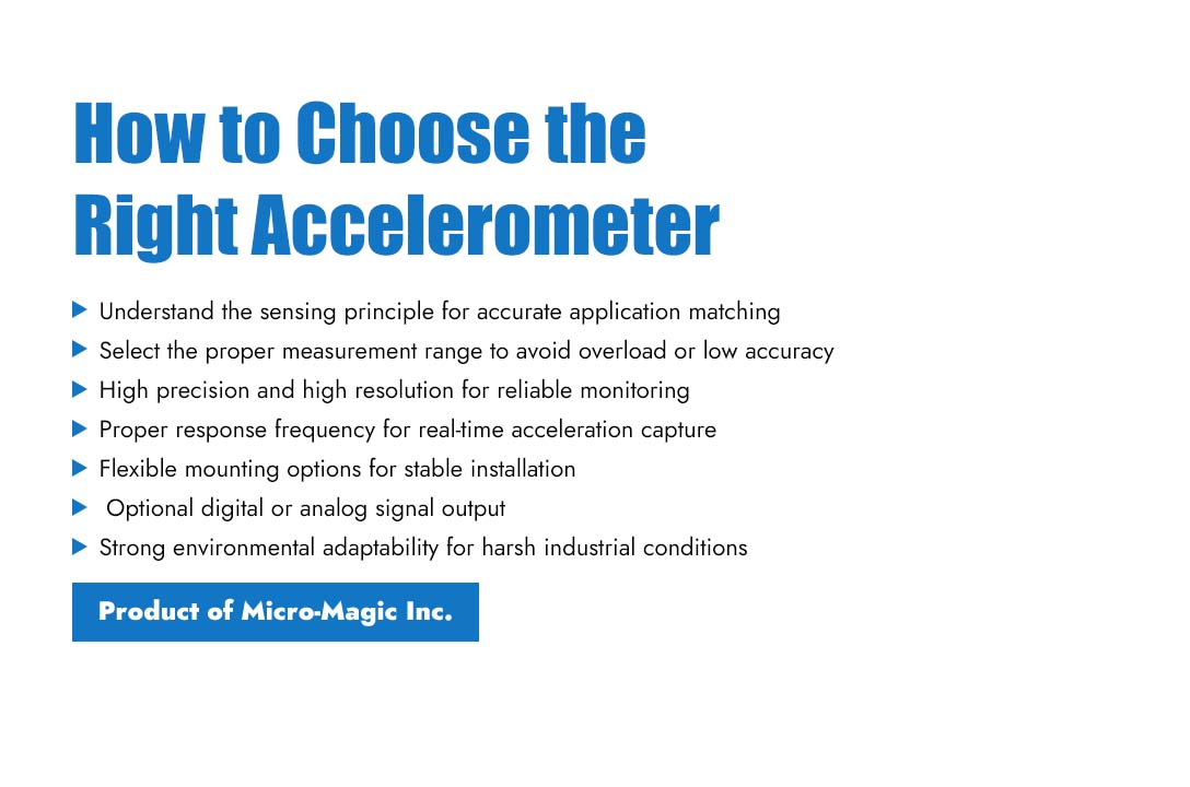
With the continuous development of industrial automation technology, accelerometers, as key components, play a crucial role in various automated equipment. To ensure the accuracy and reliability of measurement results, it's essential to select the most suitable accelerometer for a specific application. The following points are key considerations during selection: I. Understanding the Basic Principles of Accelerometers An accelerometer is a sensor that measures the acceleration of an object. Its working principle primarily involves detecting changes in the mass displacement or strain of an object under acceleration. In industrial automation, accelerometers can be used to monitor physical quantities such as vibration, tilt, and impact, thereby achieving real-time monitoring of equipment status. II. Determining the Measurement Range of the Accelerometer When selecting an accelerometer, the first step is to determine its measurement range. The measurement range refers to the maximum acceleration value that the sensor can measure. Based on the requirements of the actual application scenario, select an appropriate measurement range to avoid sensor damage due to an excessively small range or measurement inaccuracy due to an excessively large range. III. Focusing on the Accuracy and Resolution of the Accelerometer Accuracy and resolution are important indicators for evaluating the performance of an accelerometer. Accuracy refers to the deviation between the sensor's output value and the actual value, while resolution refers to the minimum change in the sensor's output signal. In the field of industrial automation, high-precision and high-resolution accelerometers are better suited to meet the high-precision monitoring requirements of equipment status. IV. Consider the Response Frequency of the Accelerometer The response frequency refers to the rate at which the output signal of an accelerometer changes when subjected to a change in acceleration. Select an accelerometer with a suitable response frequency based on different application scenarios. Sensors with high response frequencies can capture acceleration changes more quickly and are suitable for applications with high real-time requirements. V. Choose the Appropriate Installation Method When selecting a sensor, choose an appropriate installation method based on the actual application scenario and equipment structure to ensure stable and reliable sensor operation. VI. Choose the Appropriate Signal Output Method Choose between digital and analog output interfaces based on the characteristics of the application. Digital output interfaces typically include RS232, RS485/RS422, CAN, and TTL level outputs, while analog outputs typically include voltage and current outputs. VII. Consider Environmental Adaptability The environment in industrial automation is complex, and accelerometers need to have strong environmental adaptability. When selecting a sensor, it is important to consider whether it has waterproof, dustproof, and corrosion-resistant features, as well as its operating temperature range, to ensure that the sensor can still function normally in harsh environments.
Read More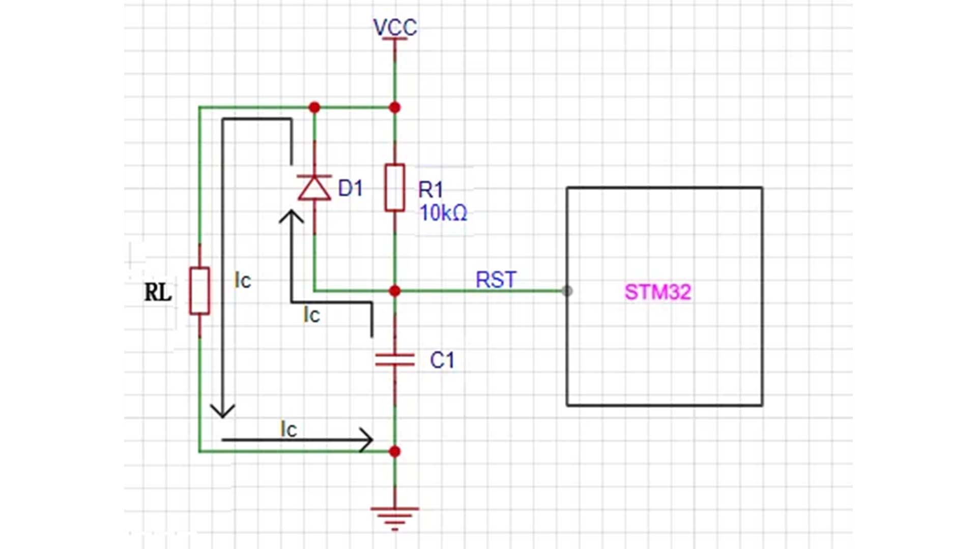
In the STM32 reset circuit shown in Figure 1, a switching diode is usually connected in parallel with the resistor terminal of the RC reset circuit. The main function of this diode is to accelerate the release of capacitor charge. Figure 1 STM32 reset circuit Figure 2 Discharge path of STM32 reset circuit In an RC reset circuit, a discharge diode is indispensable, its main function being rapid discharge. When the power is off or there is a momentary power outage due to interference, the charge stored in the capacitor needs to be released through some path to ensure proper reset upon the next power-on. Without a diode, when the power-off interference pulse is narrow, the capacitor discharges through resistor R1, which has a large resistance, resulting in a slow discharge speed. The RC circuit cannot fully discharge at the moment of power failure, and the system cannot automatically reset upon power restoration. The momentary power outage interference can cause the program to stop running normally, leading to program erratic behavior or entering an infinite loop. The addition of a diode provides a rapid discharge path for the capacitor. Due to the diode's very low on-resistance, as shown in the STM32 reset circuit discharge path in Figure 2, the charge in capacitor C1 discharges rapidly through diode D1, ensuring the stability and reliability of the reset circuit. When the power is off, the capacitor discharges rapidly to ground through the diode. When the power is restored, the capacitor has already discharged completely and can immediately begin the charging process, triggering the reset operation. This rapid discharge process ensures that the reset circuit can quickly return to its initial state after a power outage or abnormal power supply.
Read More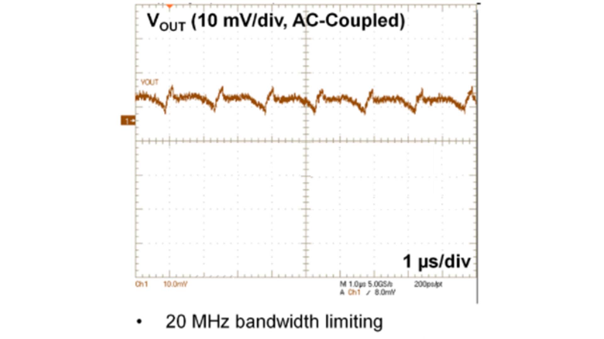
Power supply ripple refers to the periodic AC component appearing at the output of a DC power supply. Its amplitude is usually represented as peak-to-peak or peak-to-valley, as shown in Figure 1. Power supply ripple is mainly caused by waveform imperfections during power conversion, such as voltage changes caused by the switching transistors turning on and off during the operation of a switching power supply. Power supply ripple can affect the normal operation of equipment, especially for precision electronic equipment and analog circuits that require stable power supplies. Figure 1. Power supply ripple and noise Suppressing and reducing power supply ripple to a reasonable range is one of the main goals in power supply circuit design. Therefore, mastering the correct power supply ripple testing methods is crucial for subsequent power supply debugging and ripple design optimization. An oscilloscope is typically used to measure power supply ripple. By setting appropriate trigger conditions and measurement ranges, the waveform and amplitude of the ripple are observed and recorded. Furthermore, other instruments and equipment, such as a ripple coefficient tester, can be used to further analyze and quantify the characteristics of the ripple. To ensure the observation of a true and reliable ripple waveform, the following points should be noted when measuring output voltage ripple using an oscilloscope. The correct method is shown in Figure 2. 1. Select AC coupling mode on the oscilloscope; 2. To ensure signal-to-noise ratio, select X1 for probe attenuation during power supply ripple testing; 3. Set the bandwidth limit to 20MHz to avoid high-frequency noise affecting ripple measurement; 4. Minimize ground loops; a spring grounding ring is recommended as shown on the right side of Figure 2; 5. Place the probe close to both sides of the capacitor; 6. Avoid simultaneously testing waveforms at other points using other oscilloscope channels. Using the correct measurement methods described above will allow you to observe a ripple waveform similar to the one shown below. Figure 3 Ripple waveform
Read More
Recently, Micro-Magic Inc officially launched a high-performance tactical grade MEMS inertial measurement unit (IMU) product - U5000, which is a benchmark for the well-known Sensonor STIM320 series products in the industry. This domestically produced IMU not only achieves benchmarking in core performance indicators, but also demonstrates good compatibility and upgrade potential in exterior structure, electrical interfaces, and other aspects, providing a new cost-effective choice for attitude perception and navigation applications in industrial, aerospace, unmanned systems and other fields In terms of core performance indicators, U5000 demonstrates tactical level accuracy comparable to STIM320. Its gyroscope zero bias stability (Allen variance) reaches ≤ 0.1°/h, angle random walk ≤ 0.1°/√ h, accelerometer zero bias instability ≤ 30μg, overall stable and reliable performance, especially maintaining good compensation effect in the full temperature range (-40℃ to +80℃). U5000 supports a wide temperature range of -40℃ to +85℃ and has full temperature compensation, which can maintain stable output in complex environments. This product has high bandwidth (≥200Hz), good vibration and impact resistance, and demonstrates solid environmental adaptability. In terms of external dimensions, weight, and structural design, the U5000 is comparable to the STIM/320. It employs a compact package design to align with the trend of miniaturization in modern equipment. The U5000 measures 44.8×38.6×21.5 mm and weighs approximately 52 grams. With a structurally reinforced design, it is well-suited for installation in high-dynamic or harsh environments. U5000 provides clear installation benchmarks and coordinate system definitions, supports standardized operations for mechanical fixation and electrical connections, and reduces the difficulty of system integration. The data interface and communication protocol are the key to integrating IMU into the system. The U5000 is equipped with multiple communication interfaces, including RS232, RS422, as well as dedicated synchronization signals TOV and PPS inputs, supporting external GNSS receivers for time synchronization and data fusion. Its default output adopts 55AA frame format, with clear structure, complete verification, and supports user configuration of baud rate and output frequency, with strong compatibility. From the perspective of application scenarios, U5000, with its higher precision sensing performance, is mainly targeted at fields that require extremely high measurement stability, such as satellite communication dynamic communication (SOTM), high-precision surveying and mapping systems, autonomous driving testing platforms, aviation navigation and stability control, etc. The launch of U5000 marks that the company's high-performance MEMS IMU has the ability to benchmark with international mainstream products. Not only does it closely follow the STIM series in key performance parameters, but it has also been enhanced in interface flexibility, protocol openness, and other aspects, providing users with a solution with compatibility potential and more configuration freedom. With the continuous deepening of market applications, this product is expected to play an important role in unmanned systems, high-end equipment, autonomous navigation and other fields, promoting technological progress and cost optimization in related industries.
Read More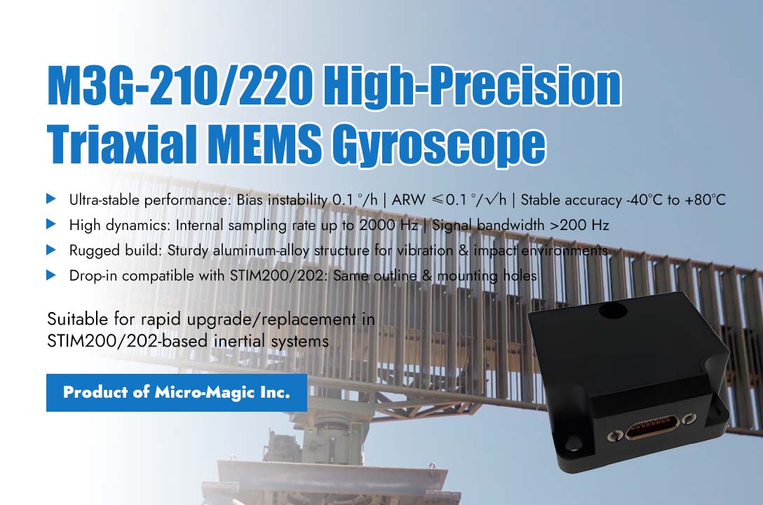
In the field of precision inertial measurement, technological innovation and system compatibility are emerging as dual engines driving industry advancement. Recently, Micro-Magic Inc launched M3G-210/220 high-precision triaxial MEMS gyroscope, with its outstanding technical performance and highly compatible design philosophy, fully matches Sensonor's STIM200/202, offering new solutions for industrial and research applications. The M3G-210/220 gyroscope exhibits significant advantages in technical performance, with zero bias instability reaching the level of 0.1 °/h, angle random walk controlled within 0.1 °/√ h, and stable measurement accuracy maintained within the working temperature range of -40℃ to +80℃. The product adopts a sturdy aluminum alloy structure design, which can adapt to complex working environments such as vibration and impact. The internal sampling rate can reach up to 2000Hz, and the signal bandwidth exceeds 200Hz, which can accurately capture rapid dynamic changes. It is worth noting that M3G-210/220 fully considers the convenience of system integration in its design. Its mechanical dimensions and interface design are fully compatible with the widely used STIM200/202 solution in the industry, including the same external specifications, matching mounting hole positions, and standardized 15 pin Micro-D connector layout. This physical compatibility enables existing systems to upgrade or replace equipment without undergoing mechanical modifications. In terms of communication protocols, the product offers multiple working modes, among which the specially optimized STIMGYRO-90 mode can achieve complete integration with the STIM200/202 system in terms of data format, instruction set, and working status. At the same time, the product also supports multiple custom communication protocols, providing users with flexible system integration options. The device retains professional functions such as external trigger input and time synchronization signal output, and has a complete system self-monitoring and status reporting mechanism. From a technical architecture perspective, the M3G-210/220 embodies a new approach to sensor design, while improving core performance indicators, it fully respects the existing technological ecosystem and reduces system integration barriers through compatibility design. This design concept enables the product to quickly integrate into various inertial measurement systems, from precision optical stabilization platforms to motion control devices, from scientific research experimental equipment to industrial detection systems, demonstrating a wide range of application potential. The balance between technological innovation and system compatibility is an important direction for the development of high-end measuring equipment. The practice of M3G-210/220 in this regard shows that through careful design, performance improvement and system adaptation can be organically unified. With the deepening application of measurement technology in various fields, this solution that combines excellent performance and good compatibility will bring more choices for system integrators and end users. At present, the product has begun to provide services to users in key areas, and its performance in practical applications deserves further attention. Under the development trend of emphasizing both technological progress and system compatibility, the launch of such products provides new possibilities for the expansion of inertial measurement technology applications.
Read More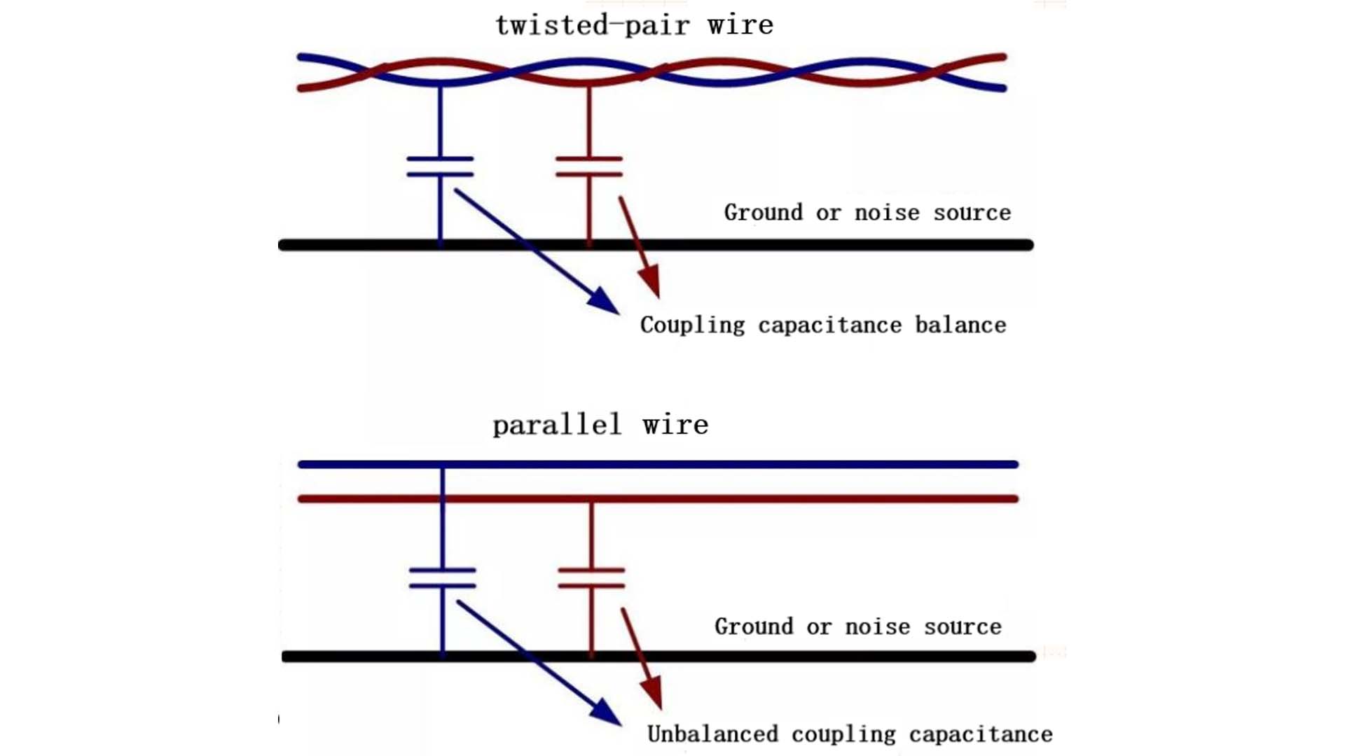
Twisted-pair cable consists of two insulated wires twisted together, making it particularly suitable for differential signal transmission. Compared to parallel wires, it can more effectively suppress interference. The characteristics of twisted-pair cable are reflected in the following two aspects: 1. Elimination of capacitive coupling Compared to parallel wires, the coupling capacitance values of each wire in a twisted-pair cable to the interference source or ground are closer, resulting in a more balanced impedance, as shown in Figure 1. Figure 1 Because the twisted pair wires are tightly wound together, the coupling capacitance between the two wires and the noise source, and the impedance to ground are essentially the same. The interference current flowing from the noise source into the two signal lines is basically identical, and the difference between the two signal lines remains unchanged. The current from the coupling capacitance is converted into common-mode interference. As shown in Figure 2, C1=C2 and Z1=Z2, so the current flowing into C1 and C2 from the interference source is equal, meaning the voltages generated on lines 1 and 2 are equal, and Vn=0. Because the differential signal transmission method has excellent common-mode rejection capability, the effects of capacitive coupling can be eliminated. Figure 2 2. Eliminating Inductive Coupling If parallel lines are used, the two signal lines will form a very narrow loop, which will pick up magnetic field interference from the environment. The structure of a twisted-pair cable involves twisting the two conductors of the transmission line at a fixed interval, causing the direction of the electromotive force induced by the magnetic field to reverse at each adjacent "small loop," thus sequentially canceling it out. From a circuit perspective, the mutual inductance at each adjacent "small loop" is opposite to the noise source, and the overall mutual inductance of the conductors becomes zero. As shown in Figure 3, when parallel lines are subjected to external magnetic field interference, the induced currents in the two conductors cannot cancel each other out, resulting in a large induced voltage that affects signal transmission. The structure of a twisted-pair cable, however, causes the induced currents in the conductors to cancel each other out, preventing the generation of an induced voltage. In differential transmission applications, twisted-pair cables can eliminate capacitive and inductive coupling with external interference sources. Therefore, twisted-pair cables are widely used in differential signal transmission applications such as CAN and RS-485.
Read More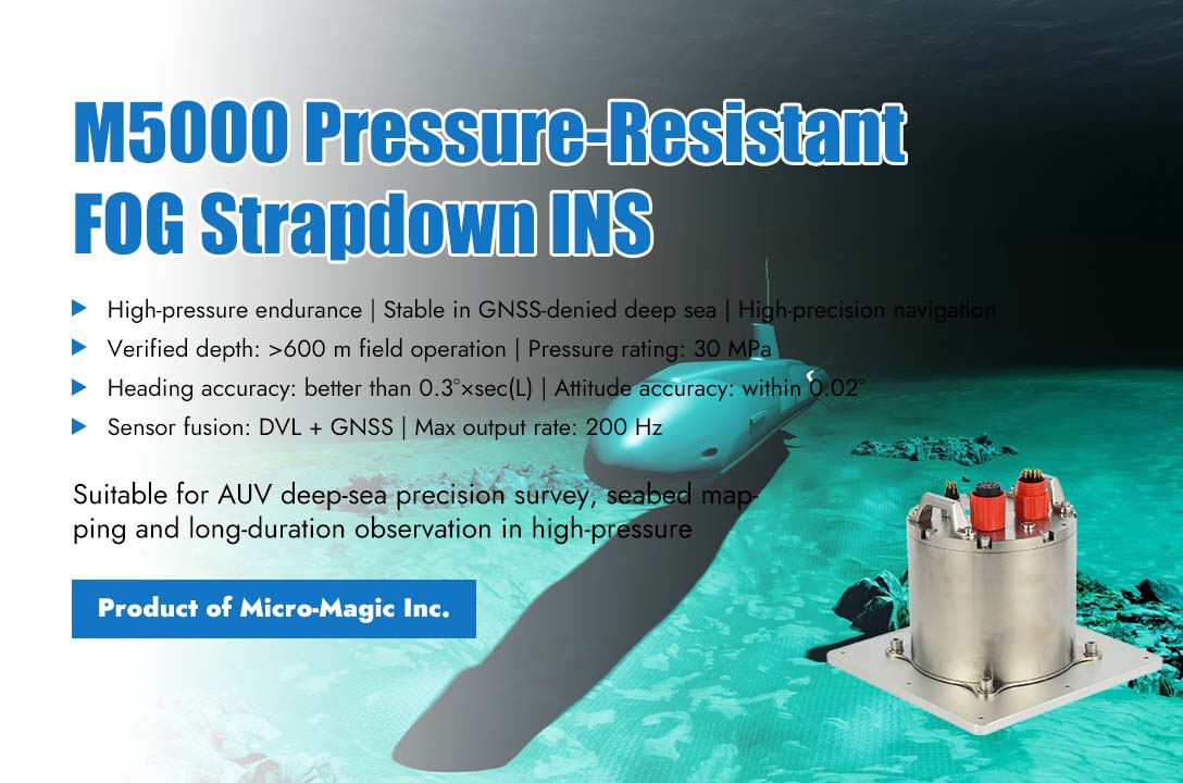
In the recently completed comprehensive deep-sea testing of a certain type of autonomous underwater vehicle (AUV), the M5000 pressure-resistant fiber optic strapdown inertial integrated navigation system developed by Micro-Magic Inc demonstrated excellent performance, successfully enabled the AUV platform to accomplish high-precision topographic mapping and prolonged continuous observation missions in 100-meter-class deep-water zones. With its excellent navigation accuracy and strong pressure resistance, the system provides reliable navigation support for deep-sea exploration equipment. In this test, the AUV was required to complete multiple dives within 15 working days, with a maximum operating depth exceeding 600 meters. Under extreme conditions such as high pressure, low temperature, and no satellite signal, the M5000 system operated stably throughout the entire process, without any data interruptions or accuracy degradation. An ocean technology expert involved in the project stated, "Deep-sea exploration has extremely stringent requirements for the accuracy and reliability of navigation systems. The M5000 can maintain a heading accuracy better than 0.3°×sec(L) and a stable attitude measurement accuracy within 0.02° even in deep-water areas where satellite signals are completely lost, providing crucial support for us to obtain high-confidence seabed topography data." As a navigation system specifically designed for deep-sea environments, the M5000 excels in pressure resistance. Its housing adopts a pressure-resistant structural design, maintaining full sealing performance under a static water pressure of 30MPa, equivalent to withstanding a pressure of 3000 meters depth. During the testing process, the system underwent nearly a hundred rapid cycles of ascent and descent, with neither its structural integrity nor electrical performance being affected. Furthermore, within the actual operating temperature range, the system effectively mitigates the impact of temperature drift on sensor accuracy through a built-in temperature compensation algorithm. In terms of data fusion and output, the M5000 system demonstrates excellent engineering applicability. The system integrates a three-axis fiber optic gyroscope and a quartz flexible accelerometer, enabling deep data fusion with multiple sensors such as Doppler Velocity Log (DVL) and GNSS receivers, with a maximum output frequency of 200Hz. Even in the event of a temporary DVL data interruption, the system can maintain stable computation through pure inertial navigation mode, ensuring that the AUV does not "lose its way" in complex hydrological environments. "The M5000 is not just a navigation unit, it serves as the 'eyes' and 'steering wheel' of the AUV in deep waters," said the project manager of Micro-Magic Inc. "We have optimized the filtering algorithm and error compensation model specifically for deep-sea applications, ensuring high accuracy consistency even during long-term operations. The success of this trial verifies our technical expertise and engineering capabilities in the field of high-precision navigation for deep seas."
Read More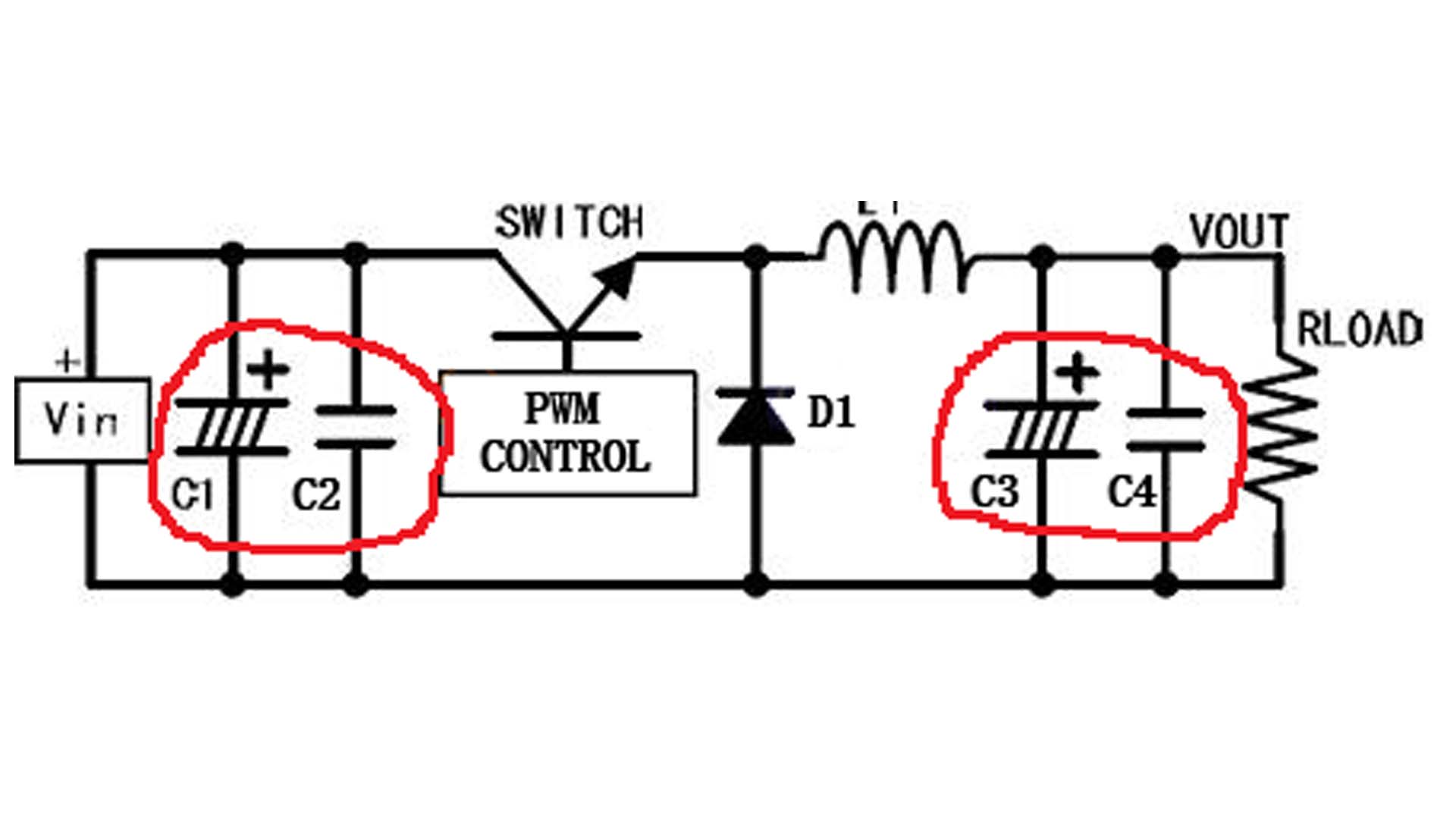
Power supply ripple, or simply ripple, is the periodic fluctuation of voltage or current in a power supply. This fluctuation poses a potential threat to the stable operation of electrical equipment. Excessive power supply ripple can reduce the power system's conversion efficiency, increase heat generation, and in severe cases, lead to system instability or even chip damage. Therefore, when designing a BUCK circuit, measures need to be taken to reduce power supply ripple to ensure system stability. The following are some common methods for reducing BUCK power supply ripple: Increase the inductance and output capacitor for filtering According to the formula for switching power supplies, the magnitude of current fluctuation within the inductor is inversely proportional to the inductance value, and the output ripple is inversely proportional to the output capacitance value. Therefore, increasing the inductance and output capacitance values can reduce ripple. Figure 1 Inductor current Figure 1 above shows the current waveform within the inductor L of a switching power supply. The ripple current ΔI can be calculated using the following formula. Based on volt-second balance and other parameters, it can be seen that increasing the inductor L value or increasing the switching frequency can reduce the current fluctuation within the inductor. Similarly, the relationship between output ripple and output capacitance is: Vripple = Imax/(Co × fsw). It can be seen that increasing the output capacitance value can reduce ripple. Commonly, aluminum electrolytic capacitors are used for the output capacitor to achieve a large capacitance. However, electrolytic capacitors are not very effective at suppressing high-frequency noise, and their ESR is relatively high. Therefore, a ceramic capacitor is connected in parallel next to it to compensate for the shortcomings of aluminum electrolytic capacitors. When a switching power supply is operating, the input voltage Vin remains constant, but the current changes with the switch. When the power supply starts up or the load changes abruptly, an input capacitor is needed as a temporary energy pool to compensate for the instantaneous drop in input voltage. Typically, a capacitor is connected in parallel near the current input terminal (near the switch in a Buck type) to provide current. The input capacitor also suppresses ripple and electromagnetic interference (EMI) from the preceding power supply. After adopting the above solution, the BUCK-type switching power supply is shown in the figure below: Figure 2 BUCK topology The above approach has limited effect on reducing ripple. Due to size limitations, the inductor cannot be made very large; increasing the output capacitor to a certain extent has no significant effect on reducing ripple; and increasing the switching frequency will increase switching losses. Second-stage filtering involves adding another LC filter LC filters are effective at suppressing noise and ripple. By selecting appropriate inductors and capacitors to construct the filter circuit based on the ripple frequency to be removed, ripple can generally be reduced significantly. However, in this case, the sampling point of the feedback comparison voltage needs to be considered. Figure 3 Selecting the sampling point before the LC filter (Pa) will result in a decrease in output voltage. This is because any inductor has a DC resistance, and when current is output, a voltage drop occurs across the inductor, causing the power supply's output voltage to decrease. Furthermore, this voltage drop varies with the output current. Selecting the sampling point after the LC filter (Pb) will produce the desired output voltage. However, this introduces an inductor and a capacitor into the power supply system, potentially affecting loop stability. After the BUCK power output, connect an LDO filter The most commonly used combination is BUCK+LDO, which is the most effective way to reduce ripple and noise. It provides a constant output voltage without requiring changes to the original feedback system, but this also reduces the overall power supply system efficiency and is the most expensive. A key metric for LDOs is PSRR (Power Supply Rejection Ratio), which quantifies the extent to which changes at the power input are transmitted to the output. After passing through an LDO, switching ripple is typically below 10mV. The PCB layout of a switching power supply is also crucial for reducing ripple. Improper component placement, unreasonable grounding, or critical traces being close to the switch-sensitive area can cause increased ripple and high-frequency noise.
Read More
Recently, MEMS technology supplier Micro-Magic Inc. launched its U4930 series high-precision MEMS inertial measurement module (IMU). This product quickly attracted the attention of integrators in the fields of industrial drones, high-precision navigation, autonomous driving, and mobile surveying, thanks to its excellent core performance, robust and compact design, and a key market positioning to become a compatible and upgrade option for Honeywell's classic HG4930 IMU. The design philosophy of U4930 is very clear: to provide more competitive performance while maintaining a physical form and electrical interface similar to the widely used HG4930 in the industry. Its external dimensions are 64.8 × 47 × 35.3 millimeters, with a weight of approximately 130 grams and a steady-state power consumption of less than 2 watts. These features enable it to seamlessly adapt to the system space and power architecture originally designed for HG4930, greatly reducing the mechanical and electrical design costs for users when replacing or upgrading products. At the performance level, U4930 has demonstrated comprehensive improvements. It integrates high-performance three-axis MEMS gyroscopes and accelerometers, and achieves precise compensation in the entire temperature range through internal algorithms. The measurement range of its gyroscope can reach up to ±500°/s, which is better than the ±400°/s of HG4930; the range of its accelerometer reaches ±30g. More importantly, its precision specifications — featuring gyro bias stability of 0.3°/h (10-second smoothing) and angular random walk as low as 0.02°/√h — enable it to meet the demands of highly stringent attitude measurement applications. At the same time, the module supports a data output rate of up to 2000Hz and is equipped with anti-vibration and anti-impact design, ensuring reliability and real-time data in high dynamic and harsh environments. U4930 adopts RS422 differential communication interface and supports custom communication protocol configured through host computer software, including synchronization support for GPS/GNSS time data and Pulse Per Second (PPS) signals, which makes it consistent with HG4930 in system integration logic. Users' existing data processing and navigation algorithms can smoothly transition. Micro-Magic explicitly stated in the information that the product is designed to be "compatible with HG4930", providing a practical and feasible technical path for existing HG4930 users seeking supply chain diversification, cost optimization, or performance improvement. The U4930 series offers three different precision levels of models, A, B, and C, covering different needs from cutting-edge scientific research to industrial applications. Its emergence marks the ability to directly benchmark with international mainstream products in the key field of high-precision MEMS inertial measurement, and through precise compatibility design, it brings users more flexible and valuable solution choices. U4930
Read More
Compared with traditional accelerometers, quartz flexible accelerometers have higher accuracy and reliability. Its high precision can be reflected in the accuracy of data, while its reliability can be reflected in the stability and lifespan of equipment operation. In addition, due to the insensitivity of quartz crystals to temperature and time changes, quartz accelerometers are also more capable of ensuring long-term and stable operation than other accelerometers. Quartz flexible accelerometers have become core sensors in aerospace, defense, industrial monitoring, and other fields due to their ultra-high precision, strong impact resistance, and extreme environmental adaptability. Aerospace and Space Exploration In spacecraft docking missions, quartz accelerometers are used to detect μg (microgravity) level acceleration, providing real-time velocity increment and attitude adjustment data to ensure docking accuracy. When the spacecraft returns to the atmosphere, it needs to withstand a high overload of 3-5g while maintaining measurement stability. When used for satellite attitude adjustment and rocket launch monitoring tasks, quartz flexible accelerometers can achieve an accuracy of 60 μg with zero bias repeatability and withstand 1000g instantaneous impact (such as rocket separation). Meanwhile, the quartz flexible accelerometer can provide gravity field data for the lander, supporting precise soft landing. In space microgravity experiments, quartz flexible accelerometers are used to measure the six degree of freedom motion of loads, with an accuracy of "observing hair falling to the ground" level to eliminate vibration interference. National Defense and Military Equipment The inertial navigation system of long-range ballistic missiles and tactical missiles relies on quartz accelerometers to maintain scale factor stability (<30ppm) in impact environments of 500-1000g, ensuring ballistic accuracy. For example, it needs to withstand 100g/5ms half sine wave impact, which is suitable for high overload at the moment of missile launch. In the application of armored vehicles and drones, the stability control of tanks and armored vehicles needs to continuously output reliable data in a vibration environment (20-2000Hz random vibration). The drone navigation system utilizes the low-power (<480mW) and lightweight (<65g) characteristics of quartz flexible accelerometers to extend range and enhance maneuverability. Industrial and Infrastructure Safety Monitoring Quartz accelerometers are applied in monitoring landslides and debris flows, capturing surface micro deformations with a resolution of μg to achieve early geological hazard warning. In deformation monitoring of bridges and high-speed railways, quartz flexible accelerometers can provide long-term stability (monthly drift<50 μg) and reduce maintenance costs. In the field of energy exploration, oil drilling measurement systems (such as wireless inclinometers) rely on their high temperature resistance (185℃) to provide inclination data in high-pressure impact environments underground. Unique Advantages Support High Demand Scenarios The core advantages of quartz flexible accelerometers lie in their ultra-high accuracy and long-term stability, with scale factor drift reaching ppm level and zero bias stability reaching μg/√h level. Taking the AC-3 series quartz flexible accelerometer produced by Micro-Magic Inc as an example: Parameters AC-3A AC-3B AC-3C Unit Threshold /Resolution 5 5 5 μg Bias drift (1σ, one month) ≤15 ≤50 ≤50 μg Repeatability of scale factor (1σ, one month) ≤15 ≤50 ≤50 ppm Bias thermal coefficient ≤ ±15 ≤ ±50 ≤ ±50 μg/℃ Scale factor thermal coefficient ≤ ±15 ≤ ±80 ≤ ±50 ppm/℃ Quartz flexible accelerometers have excellent impact resistance. Its high hardness fused silica integrated structure and frictionless flexible design enable it to withstand 1000g/0.5ms half sine impact, which is far superior to ordinary MEMS sensors. Taking the AC-4 series products produced by Micro-Magic Inc as an example: Parameters AC-4A AC-4B AC-4C Unit Shock 500g 1000g 1000g 0.5ms, 1/2sin Vibration peak sin (@30~500Hz) 25 25 25 g Quartz flexible accelerometers exhibit excellent environmental adaptability over a wide temperature range, such as . The extremely low thermal expansion coefficient and symmetrical structure of quartz material result in minimal temperature drift (as low as ppm/° C), making it a reliable choice for high-precision measurement in extreme temperature environments such as aerospace and military. Taking the AC-6 series products produced by Micro-Magic Inc as an example: Parameters AC-6A AC-6B Unit Bias thermal coefficient ≤ ±80 ≤ ±150 μg/℃ Scale factor thermal coefficient ≤100 ≤200 ppm/℃ Temperature range (Operating) -40 ~ +150 -40 ~ +150 ℃ Temperature range (Saved) -60 ~ +180 -60 ~ +180 ℃ Conclusion With its excellent precision, outstanding long-term stability, and outstanding resistance to extreme environments, quartz flexible accelerometers have firmly established their position as the core device for precise monitoring in the aerospace and military industry. It plays an irreplaceable key role in high-precision inertial navigation, aircraft attitude control, and various precision measurement tasks.
Read More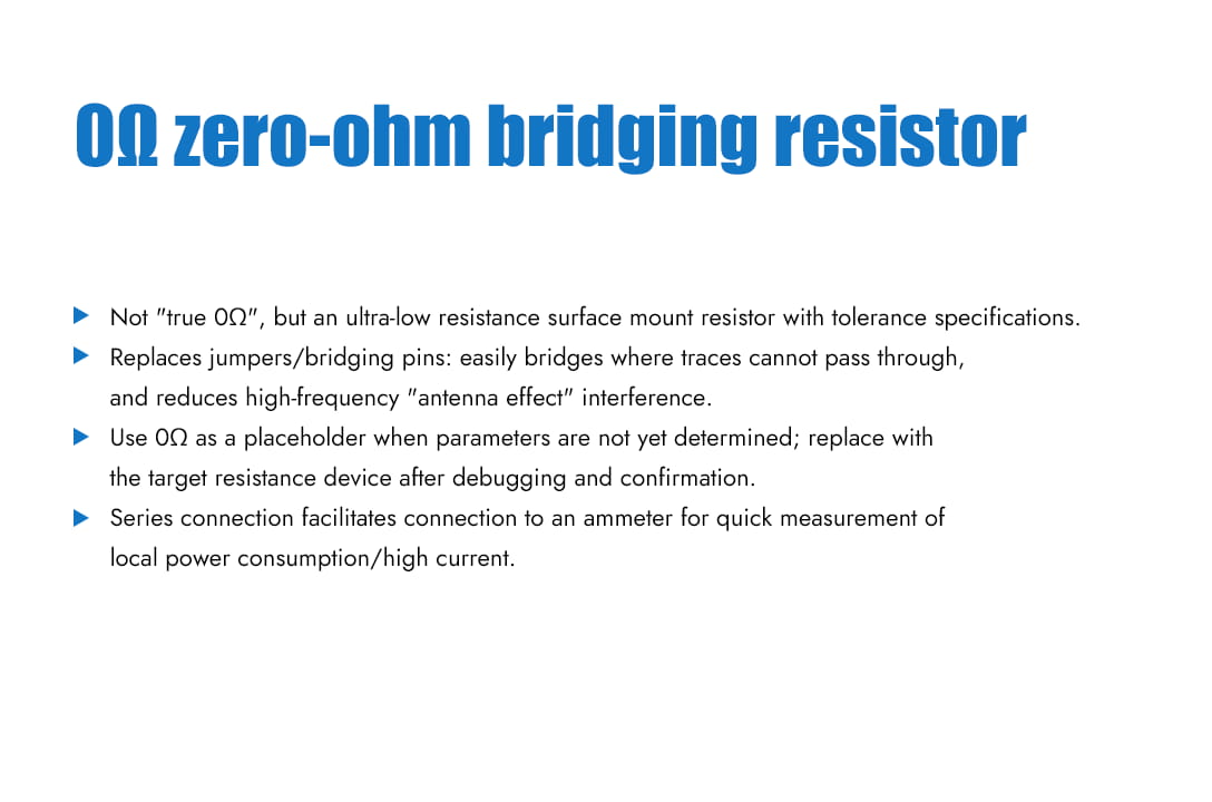
A zero-ohm resistor, also known as a jumper resistor, is a special-purpose resistor. A zero-ohm resistor does not actually have zero resistance; it is a resistor with a very small resistance value. Because it has a resistance value, it has the same tolerance and accuracy specifications as regular surface-mount resistors. In circuit board design, when two points cannot be connected using printed circuits, a jumper is often used on the front side. This is commonly seen in ordinary boards. To ensure the proper functioning of automatic pick-and-place machines and automatic insertion machines, zero-ohm resistors are used instead of jumpers. The functions of a 0-ohm resistor are as follows: 1. It has no function in the circuit; it's only used on the PCB for ease of debugging or design compatibility. 2. It can be used as a jumper to avoid high-frequency interference caused by jumper pins (acting as an antenna). 3. When the matching circuit parameters are uncertain, a 0-ohm resistor can be used as a substitute. During actual debugging, the parameters are determined, and then a component with a specific value is used as a substitute. 4. A 0-ohm resistor is actually a very small resistor. When you want to measure the current consumption of a certain part of the circuit, connect a 0-ohm resistor and an ammeter. This makes it convenient to measure the current consumption and can be used to measure large currents. 5. When routing, if it's impossible to route the circuit, a 0-ohm resistor can be added as a jumper. 6. Under high-frequency signals, it can act as an inductor or capacitor (depending on the characteristics of the external circuit). Inductors are mainly used to solve EMC problems, such as between ground and ground, power supply and IC pads. 7. Single-point grounding, meaning that protective ground, working ground, and DC ground are separated on the equipment, each becoming an independent system. 8. For circuit protection, it can act as a low-cost fuse. 9. Used for current loops when bridging. When the ground plane is split, the shortest return path for signals is broken. The signal loop must then detour, creating a large loop area. This strengthens the influence of electric and magnetic fields, making it easier to interfere with or be interfered with. Connecting a 0-ohm resistor across the split area provides a shorter return path and reduces interference. 10. In mixed-signal circuits such as digital and analog circuits, it is often required that the two grounds be separate and connected at a single point. We can use a 0-ohm resistor to connect these two grounds instead of directly connecting them together. 11. In circuit configuration, jumpers and DIP switches should generally be avoided on products. Sometimes users may tamper with settings, which can easily lead to misunderstandings. To reduce maintenance costs, 0-ohm resistors should be soldered onto the board instead of jumpers.
Read Moreleave a message
Scan to Wechat :
