




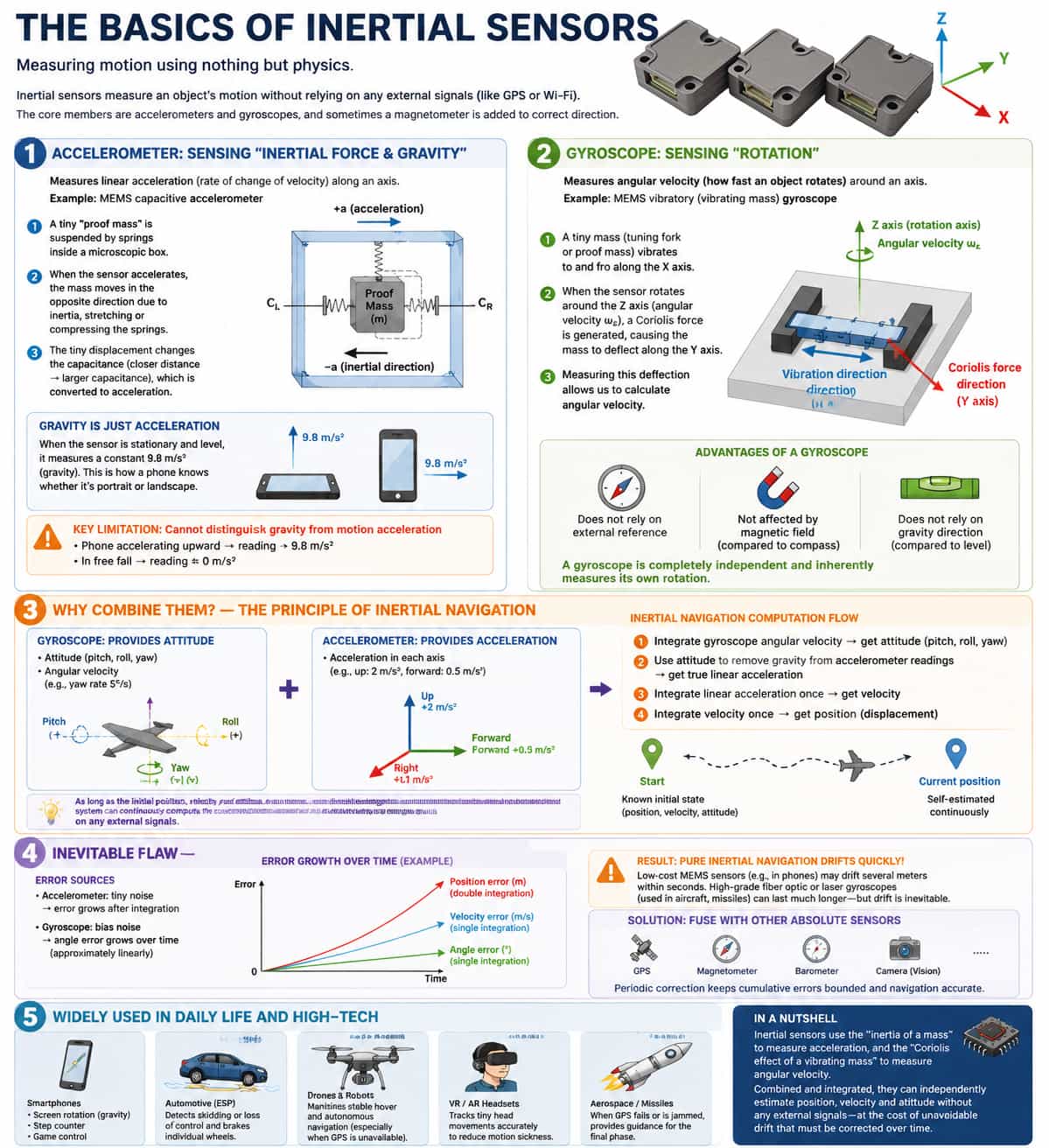
An inertial sensor is a device capable of measuring an object's motion state in space solely by relying on intrinsic physical laws, without depending on any external signals (such as GPS or Wi-Fi). Its core components are accelerometers and gyroscopes; these devices frequently work in tandem, sometimes supplemented by a magnetometer to assist in orientation correction. 1. Accelerometer: Sensing "Inertial Force and Gravity" An accelerometer measures an object's linear acceleration in a specific direction—that is, the rate at which its velocity changes. Taking the most common type—the MEMS capacitive accelerometer—as an example: imagine a tiny "proof mass" suspended by springs inside a miniature housing. When the entire sensor accelerates, the proof mass shifts in the opposite direction due to inertia, causing the springs to stretch or compress. This minute displacement is then converted into a change in capacitance (where closer proximity results in higher capacitance), thereby allowing the acceleration to be calculated. According to the General Theory of Relativity, gravity is equivalent to acceleration; therefore, when the sensor is stationary and lying flat, it registers a constant reading of 9.8 m/s² (the acceleration due to gravity). This is precisely how a smartphone determines whether it is in "landscape" or "portrait" mode—by sensing the direction of gravity. However, accelerometers possess a critical limitation: they cannot distinguish between gravity and acceleration caused by motion. For instance, if a smartphone accelerates vertically upward, its reading will exceed 9.8 m/s²; conversely, during free fall, the reading will approach zero. 2. Gyroscope: Sensing "Rotation" A gyroscope measures an object's angular velocity—the speed at which it rotates—around a specific axis. Using the MEMS vibratory gyroscope as an example, this device harnesses the physical phenomenon known as the Coriolis effect: imagine a tiny tuning fork or proof mass being driven to oscillate rapidly back and forth. When the sensor as a whole rotates, this oscillating mass is subjected to a force—the Coriolis force—that acts perpendicular to both the direction of oscillation and the axis of rotation. This force causes the mass to undergo a minute lateral displacement; by measuring the magnitude of this displacement, the angular velocity of the rotation can be calculated. The value of the gyroscope lies in its independence from external references; it is inherently capable of measuring its own rotation. This capability renders it more powerful than devices such as compasses or spirit levels: while a compass is susceptible to interference from magnetic fields and a spirit level requires the reference of gravity, a gyroscope operates in complete autonomy. 3. Why is a Combination of Both Necessary? — Principles of Inertial Navigation Using accelerometers or gyroscopes in isolation presents inherent challenges; however, by combining both with data fusion algorithms, inertial navigation can be achieved. The gyroscope provides information regarding current attitude and rotational velocity (e.g., "oriented 30° east of North, rotating at 5° per second"), while the accelerometer reports acceleration along various axes (e.g., "upward acceleration is 2 m/s², forward acceleration is 0.5 m/s²"). However, to subtract the gravitational component from these readings, the current attitude—provided by the gyroscope—must be known. The specific calculation process unfolds as follows: integrating the gyroscope's angular velocity yields the attitude (pitch, roll, and yaw angles); using this attitude information, the gravitational component is subtracted from the accelerometer readings to derive the true acceleration of motion; integrating this motion acceleration once yields velocity, and integrating the velocity once more yields displacement (change in position). Consequently, provided that the initial position, velocity, and attitude are known, an inertial navigation system can continuously calculate and output the current position and orientation throughout any movement, operating entirely independently of external signals. 4. An Inherent Flaw That Must Be Addressed—Drift Inertial sensors suffer from an unavoidable drawback: cumulative integration error—commonly referred to as "drift." Accelerometers exhibit minute levels of noise; when integrated to derive velocity, this error is amplified once, and when integrated again to derive displacement, the error escalates dramatically. Simultaneously, gyroscopes also introduce minute errors in their angular velocity measurements; when integrated to derive angular position, this error grows linearly over time. The result is that a purely inertial navigation system will develop significant deviations within a span ranging from a few seconds to a few minutes. While expensive fiber-optic or laser gyroscopes (typically used in aircraft and missiles) can maintain accuracy for longer periods, the inexpensive MEMS sensors found in mobile phones may drift by several meters within just a few seconds. Therefore, it is essential to periodically correct the cumulative errors of inertial sensors by utilizing other absolute measurement sensors—such as GPS receivers, magnetometers, barometers, or vision cameras. 5. Ubiquitous Applications in Daily Life Inertial sensors are widely applied in both everyday life and high-tech fields: in mobile phones, they enable screen rotation (accelerometers sense gravity), step counting (accelerometers detect the vibrations of walking), and directional control in games (gyroscopes); in automotive Electronic Stability Programs (ESP), they detect whether a vehicle is fishtailing or skidding, allowing for the instantaneous braking of individual wheels; in drones and robots, they maintain stable hovering and facilitate autonomous navigation (particularly when GPS signals are lost); in VR/AR headsets, they precisely track minute head movements to minimize motion sickness; and in aerospace and missile systems, they serve as the primary guidance mechanism during the final stages of flight, or whenever GPS signals fail or are subject to interference. In summary, inertial sensors measure acceleration by leveraging the "inertia of a proof mass" and measure angular velocity by utilizing the "Coriolis effect on a vibrating mass." By combining these measurements and performing integration calculations, they can autonomously determine an object's position, velocity, and attitude without relying on any external signals—though this capability comes with the inherent trade-off of accumulating drift errors over time.
Read More
Inertial sensor original manufacturers—operating under the IDM (Integrated Device Manufacturer) model, which entails in-house R&D and manufacturing—realize a "full-link" advantage. This advantage represents not merely a closed loop in technical methodology, but a profound transformation spanning from foundational technology to commercial returns. Specifically, this is manifested in the following five aspects: I. Comprehensive Strategic Advantages The full-link advantage inherent in an original manufacturer's in-house R&D and production is demonstrated by its autonomous and controllable command over the entire process—from chip design, fabrication, and packaging to testing—thereby fundamentally guaranteeing supply chain security. Building upon this foundation, R&D teams can engage in vertical collaboration to accelerate technological iteration and integration; for instance, Maxinmin Micro’s inertial sensors have achieved a high degree of single-chip integration encompassing sensing, computation, and security functions, thereby meeting rigorous functional safety standards. Ultimately, this deep level of control enables the enterprise to precisely grasp market demands, offer differentiated products, and respond rapidly to both domestic and international clients, thereby establishing powerful competitive strength in the realm of domestic substitution. II. Core Technology and Product Performance Advantages The full-link closed loop inherent in an original manufacturer's in-house R&D and production fundamentally alters the logic behind enhancing inertial sensor performance. In traditional models, where various stages are fragmented, optimizing a single metric often comes at the expense of other performance indicators. Conversely, full-link collaboration allows for the simultaneous, system-level optimization of sensitive structures, circuitry, packaging, and algorithms; this approach not only ensures low noise and low drift but also significantly enhances stability across the full operating temperature range as well as vibration resistance. The autonomous and controllable nature of the entire process ensures that every single chip can be traced back to its specific process parameters; when combined with closed-loop feedback derived from batch testing, this capability ensures high consistency across different production batches and enables the long-term predictability and controllability of product performance. This marks a fundamental leap forward—transitioning from merely leading in "individual performance metrics" to achieving comprehensive excellence in "robustness, consistency, and predictability." III. Cost Control and Rapid Customization Advantages Full-link autonomous technology enables the enterprise to deeply integrate every stage of the process, from design through to production, thereby conferring two core advantages: First, Rapid Customization—the R&D team can flexibly adjust product specifications, performance parameters, and even packaging formats in accordance with specific client requirements, completing the development and delivery of customized products within extremely short timeframes without being constrained by the procedural limitations of external suppliers. Second, Ultimate Cost Control—by vertically integrating and eliminating intermediate links within the industry chain, and by continuously optimizing yield rates and efficiency throughout the entire process, the enterprise can minimize production costs while simultaneously guaranteeing high performance; this ensures that even customized products can benefit from the cost advantages typically associated with mass production. This capability—characterized by "on-demand customization and controllable costs"—is precisely what distinguishes full-link autonomous technology from traditional models. IV. Advantages in Supply Chain Security and Autonomous Control The full-link advantage ensures that critical core components no longer rely on imports, thereby fundamentally mitigating "choke-point" risks and safeguarding national defense and infrastructure security. Through independent innovation, enterprises can construct a "patent wall" of core technologies, establishing a comprehensive and dense intellectual property portfolio. Building upon this foundation, they can—starting from the top-level design phase—formulate supply chain management processes that adhere to the highest security standards, while simultaneously securing certifications for full localization and autonomous control from authoritative bodies. Furthermore, this approach enables the comprehensive lifecycle management and optimization of products—spanning design, verification, production, and improvement—thereby ensuring that the entire process remains under autonomous control. V. Advantages in Application Coverage and Ecosystem Empowerment Leveraging its full-link autonomous technology, Maixinminwei’s inertial sensor products systematically cover a spectrum of high-end application scenarios, ranging from industrial-grade to tactical-grade and navigation-grade levels. In the industrial and infrastructure sectors, these products are widely deployed in applications such as high-speed rail and bridge monitoring, industrial equipment condition monitoring, and structural health monitoring, meeting stringent requirements for long-term reliability and adaptability to harsh environments. In tactical-grade applications, the company provides high-precision attitude sensing and motion control capabilities for platforms including drones, unmanned ground vehicles, unmanned surface and underwater vessels, and various robotic systems. In navigation-grade applications, the products satisfy the operational stability requirements of high-reliability, high-dynamic environments—such as those involving low-earth orbit satellites, microsatellites, drone swarms, aerospace systems, and defense equipment. Moreover, the company offers a "Sensor + Algorithm + Application Solution" one-stop service, significantly lowering the barrier to entry for customers. This service also allows for the rapid customization of products based on specific requirements, thereby delivering precisely tailored, high-end inertial sensing solutions to customers across diverse sectors and operational tiers. Conclusion The full-link advantage—characterized by in-house R&D and manufacturing—fundamentally represents a restructuring of the entire value chain. It marks a transition from passively embedding within foreign technology ecosystems to autonomously defining standards, controlling costs, and driving iterative innovation. This strategic shift enables the enterprise to simultaneously ensure supply chain security while driving down the cost of high-performance sensors to a critical threshold—the point at which mass adoption becomes economically viable. In doing so, it paves the way for the large-scale application of high-end inertial sensors in strategic, cutting-edge fields such as aerospace, defense equipment, and deep-sea exploration.
Read More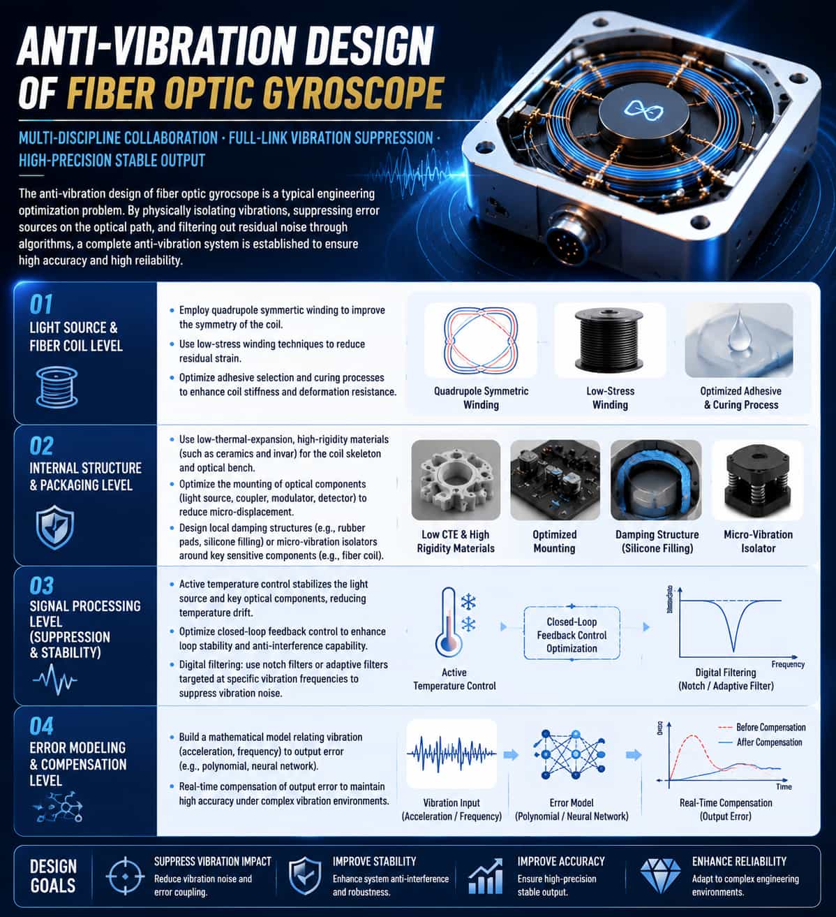
The anti-vibration design of fiber optic gyroscope is a typical engineering optimization problem that requires collaborative efforts in mechanical structure, optical path design, and signal processing. The current mainstream solution is to physically isolate vibrations, suppress error sources on the optical path, and filter out residual noise through algorithms, thus forming a complete anti-vibration system. At the light source and fiber coil level, the design of the fiber coil is optimized by employing quadrupole symmetric winding, low-stress winding techniques, and optimizing adhesive selection and curing processes to enhance the coil's stiffness and resistance to deformation. At the internal structure design and packaging level, materials with low thermal expansion coefficients and high rigidity (such as ceramics and invar) are used to fabricate the coil skeleton and optical bench, and the mounting methods of optical components (light source, coupler, modulator, detector) are optimized to reduce micro-displacement. Simultaneously, local damping structures (such as rubber pads, silicone filling) or micro-vibration isolators are designed around key sensitive internal components of the gyroscope (such as the fiber coil). At the signal processing level, active temperature control is used to stabilize the temperature of the light source and key optical components, thereby reducing temperature drift. Closed-loop feedback control is optimized to enhance the stability and anti-interference capability of the control loop. Digital filtering techniques, such as notch filters or adaptive filters designed for specific vibration frequencies, are employed to suppress vibration noise during signal processing. Additionally, through error modeling and compensation, a mathematical model (e.g., polynomial, neural network) relating vibration (acceleration, frequency) to output error is established to enable real-time compensation in the output.
Read More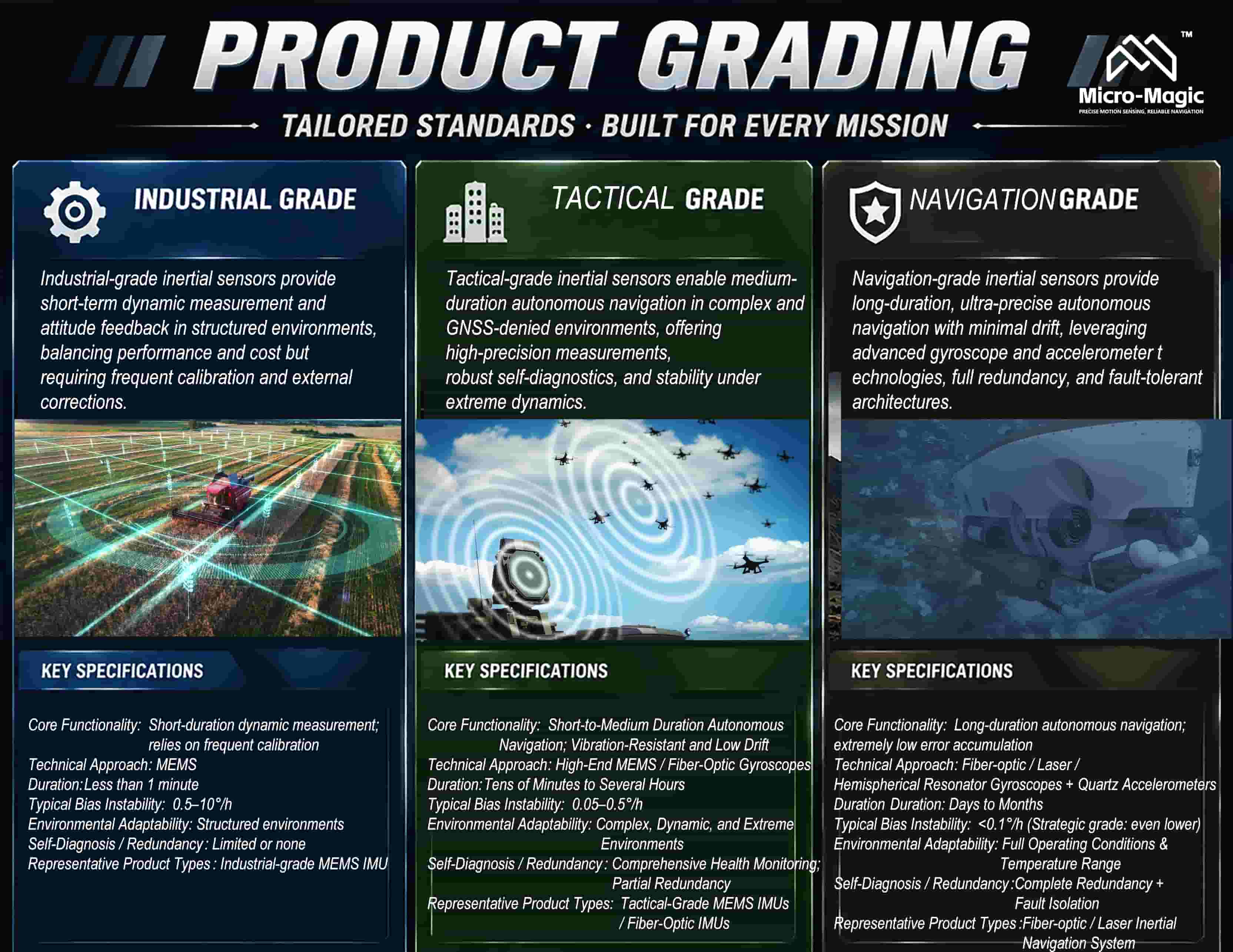
The classification of inertial sensors is, in essence, determined by the duration for which they can maintain autonomous inertial navigation accuracy in the absence of external corrections (such as GNSS). Different grades correspond to distinct hardware architectures, signal processing algorithms, and application scenarios. The following analysis deconstructs the functional characteristics of three specific grades—industrial, tactical, and navigation—across four key dimensions: functional positioning, core technologies, typical performance metrics, and applicable scenarios. 1. Industrial-grade Inertial Sensor Functional Positioning: Provides short-duration dynamic measurement and attitude feedback within structured environments. It typically relies on external sensors (GPS, vision, LiDAR) for frequent calibration to maintain system accuracy. The industrial grade functions as a "calibration-dependent" sensor. Key Technologies: Most industrial-grade inertial sensors utilize MEMS technology, featuring silicon micromechanical structures and capacitive sensing. Static calibration—including zero bias, scale factor, and axis alignment—is performed prior to shipment. Select mid-to-high-end products feature full-temperature compensation (ranging from -40°C to 85°C), as well as digital interfaces (such as SPI, I²C, CAN, RS232, RS422, etc.) and integrated filtering. Typical Performance: Industrial-grade Inertial Sensors—Gyro Bias Instability: 0.5°/h to 10°/h; Accelerometer Bias Instability: 10 μg to 1000 μg; Angular Random Walk: 0.2°/√h to 0.5°/√h; Pure Inertial Navigation Duration: Less than 1 minute (requires frequent correction). Functional Breakdown: Industrial-grade inertial sensors output raw angular rates and acceleration (IMU), fused attitude angles (AHRS), or position and velocity information (GNSS/INS integrated navigation systems). Signal conditioning circuitry performs preliminary noise suppression; some products feature built-in digital filters with configurable bandwidth. Self-diagnostic capabilities are limited, and redundancy designs are typically absent. Typical Applications: The industrial grade represents the most widely adopted classification currently utilized in the fields of robotics, autonomous driving, and industrial automation, emphasizing a balance between performance and cost. Specific applications include: attitude control for industrial robot arms and end-effector positioning (attitude accuracy of 0.1°, end-effector positioning accuracy of ±0.3 mm); indoor navigation and dead reckoning for AGVs and AMRs (with a zero-bias drift of 1.5–6°/h, meeting basic mobility requirements); flight attitude control for plant protection drones in precision agriculture (attitude accuracy of 0.1°, resulting in a >15% improvement in spray uniformity); and stabilization platform applications, such as camera gimbals and antenna stabilization (with a jitter amplitude of <0.02°). 2. Tactical-grade Inertial Sensors Functional Positioning: To provide medium-duration autonomous navigation capabilities within complex, dynamic, and extreme environments. It is capable of maintaining acceptable navigation accuracy even if GNSS signals are lost for periods ranging from tens of minutes to several hours. The tactical grade serves as the core implementer of "short-to-medium-duration autonomous navigation." Key Technologies: Tactical-grade inertial sensors employ high-performance MEMS or Fiber Optic Gyroscope (FOG) technology. They feature full-temperature-range dynamic compensation (-40°C to +85°C, or even wider), with each individual sensor utilizing its own independent compensation formula. They incorporate structural designs for vibration suppression (utilizing vibration-absorbing materials and sealed enclosures) or employ algorithmic compensation techniques. High-precision inter-axis alignment is utilized (with an error margin of less than ±0.05°), and the units feature built-in self-diagnostic and health monitoring capabilities. Typical Performance: For tactical-grade inertial sensors, typical performance specifications include: Gyroscope Bias Instability of 0.05°/h to 0.5°/h; Accelerometer Bias Instability of 1 μg to 10 μg; and Angle Random Walk of 0.05°/√h to 0.15°/√h. Pure inertial navigation can be sustained for durations ranging from several tens of minutes up to several hours. Functional Breakdown: Tactical-grade inertial sensors output stabilized angular rates and accelerations that have undergone both temperature compensation and vibration suppression. They can provide fused attitude angles (AHRS) or integrated navigation data. They support high-frequency output (≥200 Hz) to meet the demands of high-dynamic response scenarios. Comprehensive self-diagnostic functions are included to flag sensor anomalies or instances where performance thresholds have been exceeded; furthermore, some tactical-grade IMUs feature redundant sensors or dual-backup designs. Typical Applications: Missile Guidance (flight durations of tens of seconds to several minutes; a bias instability of 0.1–1°/h is sufficient); Rocket/Artillery Shell Guidance (high-G overload environments, requiring tactical-grade MEMS sensors); L4+ Autonomous Driving (GPS-denied scenarios such as tunnels or urban canyons, achieving a position error of <0.8 meters after 60 seconds); Military UAVs (medium-to-high altitude reconnaissance flights, achieving attitude control precision of 0.01° and a 25% improvement in reconnaissance image resolution); Satellite-on-the-Move (SOTM) Antennas (maintaining stable satellite signal reception while in motion); and Counter-UAS (C-UAS) Systems (enabling rapid target acquisition and tracking). 3. Navigation-grade inertial sensors Functional Positioning: To achieve high-precision autonomous navigation over extended periods without external correction. Errors accumulate slowly over time (approximating linear growth) rather than diverging abruptly. The "navigation grade" represents the cornerstone of "long-duration, unaided navigation." Key Technologies: Navigation-grade inertial sensors are centered around Fiber Optic Gyroscopes (FOG), Ring Laser Gyroscopes (RLG), or Hemispherical Resonator Gyroscopes (HRG); accelerometers typically utilize Quartz Flexure Accelerometers (Q-Flex), characterized by extremely low noise levels. These systems feature ultra-low random noise designs, with Allan variance curves approaching theoretical limits. They undergo precise calibration and compensation across their full operating temperature range and full measurement scale, achieving inter-axis orthogonality at the arc-second level. Furthermore, they incorporate multi-redundant architectures and fault isolation capabilities. Typical Performance: For navigation-grade inertial sensors: Gyro bias instability is <0.1°/h (strategic-grade units can reach as low as 0.0001°/h); accelerometer bias instability ranges from 1 μg to 10 μg (high-end units can be <1 μg); Angle Random Walk (ARW) is <0.03°/√h (high-end units can reach as low as 0.005°/√h); and the sustainment duration for pure inertial navigation ranges from several days to several months. Functional Breakdown: Navigation-grade inertial sensors output exceptionally clean angular rate and acceleration data, virtually free from thermal drift and random noise. They feature internally integrated high-precision analog-to-digital conversion and high-speed digital signal processing circuitry. They support multi-sensor redundancy management, ensuring that a single point of failure does not compromise overall navigation integrity. Additionally, they can output specific force information—precisely compensated using gravity models—to facilitate tight coupling with external high-precision sensors, such as star trackers and Doppler velocimeters. Typical Applications: Long-duration, unaided navigation for nuclear submarines and strategic bombers; inertial guidance for Intercontinental Ballistic Missiles (ICBMs); attitude and orbit control for spacecraft and satellites; long-range Unmanned Underwater Vehicles (UUVs); and high-precision gravimetric mapping and north-finding. Summary Comparison Table Functional Dimensions Industrial Grade Tactical Grade Navigation Grade Core Functionality Short-duration dynamic measurement; relies on frequent calibration Short-to-Medium Duration Autonomous Navigation; Vibration-Resistant and Low Drift Long-duration autonomous navigation; extremely low error accumulation Technical Approach MEMS High-End MEMS / Fiber-Optic Gyroscopes Fiber-optic / Laser / Hemispherical Resonator Gyroscopes + Quartz Accelerometers Duration Less than 1 minute Tens of Minutes to Several Hours Duration: Days to Months Typical Bias Instability 0.5–10°/h 0.05–0.5°/h <0.1°/h (Strategic grade: even lower) Environmental Adaptability Structured environments Complex, Dynamic, and Extreme Environments Full Operating Conditions & Temperature Range Self-Diagnosis / Redundancy Limited or none Comprehensive Health Monitoring; Partial Redundancy Complete Redundancy + Fault Isolation Representative Product Types Industrial-grade MEMS IMU Tactical-Grade MEMS IMUs / Fiber-Optic IMUs Fiber-optic / Laser Inertial Navigation System
Read More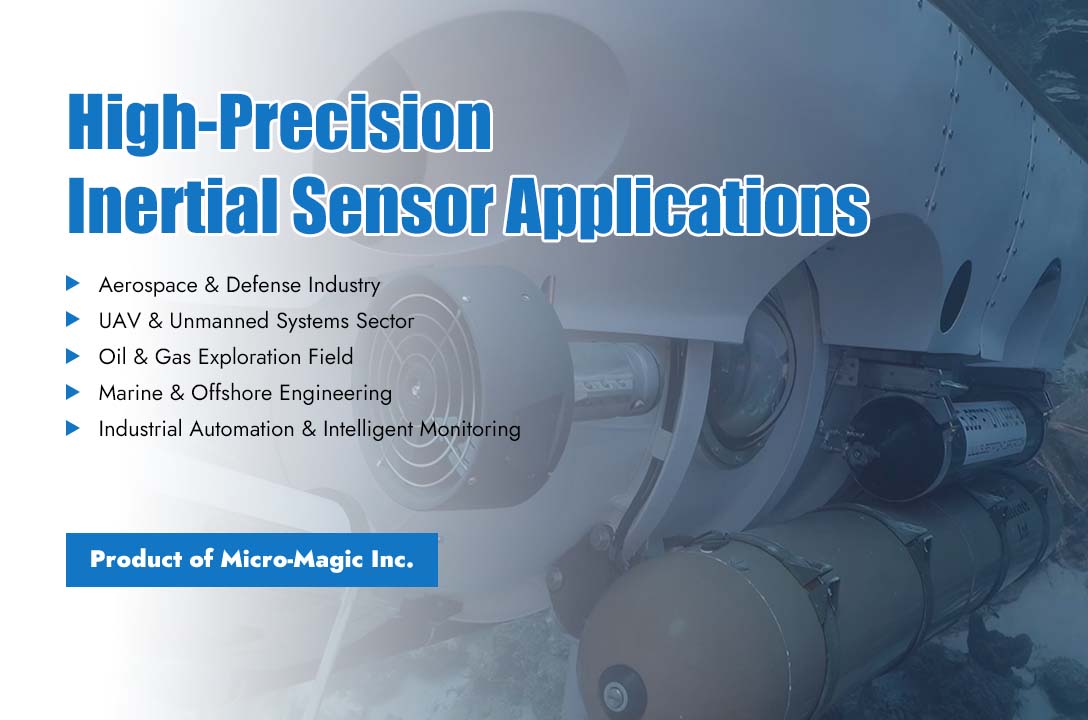
As a vertically integrated original manufacturer of inertial sensing technology, Micro-Magic Inc has built a comprehensive industrial layout covering aerospace, unmanned aerial vehicles (UAVs), oil and gas exploration, marine engineering, and industrial automation. Leveraging self-developed fiber optic gyroscopes, quartz flexure accelerometers, MEMS magnetometers, and multi-grade inertial navigation systems, the company provides customized high-precision sensing solutions for diversified harsh and high-standard industrial scenarios. With verified technical validation and mass delivery experience across global industries, Micro-Magic has formed a mature application ecosystem that adapts to extreme temperatures, intense vibration, high shock, and long-duration uninterrupted operation, consolidating its leading position in the high-end inertial measurement industry. 1. Aerospace & Defense Industry Micro-Magic Inc delivers navigation-grade and tactical-grade inertial products tailored for aerospace and defense scenarios with stringent precision and reliability requirements. The company’s high-performance fiber optic gyroscopes and temperature-resistant quartz accelerometers serve as core attitude measurement components for aviation equipment, providing stable angular velocity and acceleration data for flight attitude control, azimuth positioning, and gyro north-finding systems. All aerospace-grade products undergo strict high-low temperature circulation, anti-shock, and anti-vibration calibration in the in-house laboratory, adapting to drastic air pressure and temperature changes during high-altitude flight. The self-calibration electronic compass series further enhances heading accuracy for aerospace carriers, supporting long-endurance autonomous navigation without external signal assistance, which is widely applied in aviation attitude monitoring and defense-level positioning systems. 2. UAV & Unmanned Systems Sector Focusing on the booming unmanned system market, Micro-Magic launches optimized MEMS IMUs and lightweight inertial modules for industrial and tactical UAVs. Different from consumer-grade low-precision sensors, the company’s UAV-dedicated inertial products feature low drift, high dynamic response, and compact integration structure, perfectly matching the lightweight and high-maneuverability characteristics of unmanned aerial vehicles. These products provide real-time attitude, angle, and displacement data for aerial surveying, inspection, and industrial unmanned drones, realizing stable hovering, fixed-point navigation, and intelligent obstacle avoidance. Benefiting from independent algorithm optimization, Micro-Magic’s UAV sensors effectively suppress cumulative errors during long-term flight, ensuring continuous and reliable positioning performance for commercial and industrial unmanned aerial systems. 3. Oil & Gas Exploration Field Against the backdrop of harsh underground exploration environments, Micro-Magic has developed extreme-environment-resistant inertial sensing products represented by the AC-6 high-precision quartz flexure accelerometer. Designed for oil drilling and geological exploration scenarios, the AC-6 series withstands extreme temperatures up to 180°C and ultra-high shock impact of 1000g, with a wide bandwidth ranging from 800Hz to 2500Hz. It accurately captures underground attitude data during drilling operations, assisting engineers in well trajectory monitoring and geological parameter analysis. Combined with high-stability inertial measurement modules, the company’s products solve technical pain points such as high temperature interference and vibration signal distortion in petroleum exploration, providing reliable data support for resource exploitation, geological monitoring, and downhole attitude positioning. 4. Marine & Offshore Engineering Micro-Magic supplies professional marine-grade inertial sensing systems for offshore exploration, subsea mapping, and marine vessel navigation. The company’s fiber optic gyroscope north finders and waterproof inertial navigation modules adapt to high humidity, salt corrosion, and turbulent water flow in marine environments. These products deliver high-precision true north positioning and real-time attitude feedback for offshore operating platforms, unmanned underwater vehicles, and marine surveying vessels. With excellent long-term stability and anti-interference capability, Micro-Magic’s marine sensors effectively reduce navigation errors caused by ocean current fluctuations, supporting marine resource exploration, underwater topographic mapping, and maritime safety monitoring projects. 5. Industrial Automation & Intelligent Monitoring For industrial automation and intelligent equipment monitoring, Micro-Magic launches the ACM1000 intelligent vibration sensor and industrial-grade MEMS inertial modules. The ACM1000 sensor achieves ultra-high measurement accuracy with displacement precision of ±0.001mm and angular velocity accuracy of ±0.001°/s, capable of synchronous output of speed, displacement, frequency, and temperature data. Featuring ultra-high shock resistance of 20000g and an MTBF exceeding 45000 hours, this product adapts to long-term uninterrupted operation of industrial equipment. Compatible with diversified communication protocols including RS485, RS232, and CAN, it is widely used for mechanical vibration monitoring, equipment fault early warning, and automated production line attitude calibration, ensuring operational safety and intelligent management of industrial facilities. In conclusion, relying on independent R&D, in-house manufacturing, and a fully controlled supply chain, Micro-Magic Inc has completed full coverage of high-value industries from civil industrial automation to high-end aerospace defense. By continuously iterating quartz accelerometers, fiber optic gyroscopes, and MEMS sensing products, the company tailors targeted inertial measurement solutions for different extreme working conditions, forming unique industrial competitive advantages. In the future, Micro-Magic will continue to deepen its global industrial layout, empowering intelligent upgrading and high-precision measurement of various industries with reliable inertial sensing technology.
Read More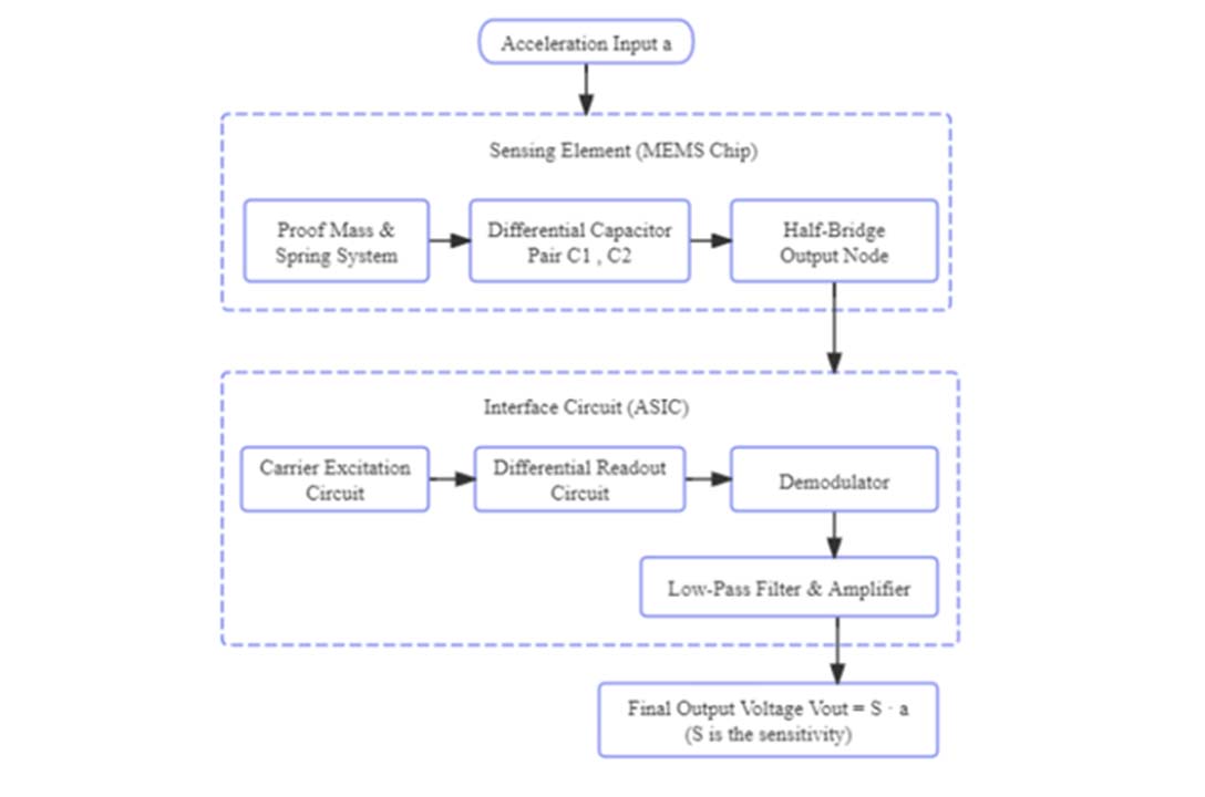
In differential capacitive accelerometers, the core design is a "sandwich" structure: a movable sensitive mass block in the middle (as a common electrode), and fixed electrodes on the upper and lower sides. When there is no acceleration, the mass block is located in the center, and the upper and lower capacitors are equal: When the acceleration α acts along the sensitive axis direction, the inertial force causes the mass block to produce displacement . At this time, the upper and lower capacitors become: The design scheme usually uses a differential half bridge circuit to extract signals. The relationship between output voltage and capacitance difference is: Substitute the above capacitance expression: Therefore, a concise linear relationship is obtained: Combined with the mechanical equilibrium equation (where k is the stiffness of the elastic beam), the final result is: The brilliance of this design scheme lies in the fact that the output is strictly proportional to the acceleration α, and the denominators and can be precisely controlled through photolithography accuracy, allowing for precise sensitivity design. Meanwhile, the differential structure eliminates common mode interference (such as temperature drift and power supply fluctuations), making it a very mature solution in engineering.
Read More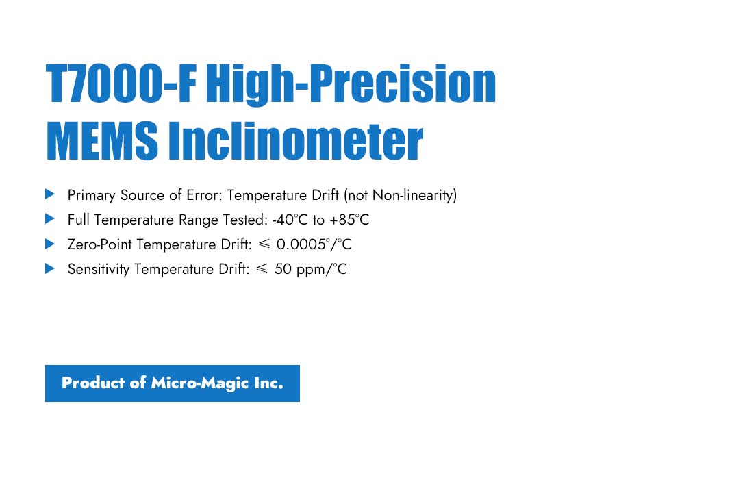
MEMS inclinometers must undergo full-temperature testing, as temperature variation—not nonlinearity—constitutes their largest error source. The elastic modulus of sensitive materials, reference voltage, and amplifier gain all drift with temperature. Full-temperature testing allows these effects to be assessed and compensated, guaranteeing measurement accuracy over the full operating temperature range. Taking the high-precision inclinometer T7000-F manufactured by Micro-Magic Inc as an example, during the full-temperature cycling test, the T7000-F is fixed at a non-zero angle (e.g., +10°) with its mechanical angle kept unchanged throughout the entire process. Starting from room temperature (25°C, ambient temperature), the temperature is decreased to -40°C and held for a sufficient duration. Then, at a set temperature change rate, the temperature is increased to +85°C and held again. Finally, optionally, the temperature may be returned to room temperature. Throughout the entire cycling process, the angular output θ(T) is continuously monitored and recorded at several temperature points: 25°C (ambient temperature), -40°C, 25°C, 85°C, and 25°C (return check). Based on these measurements, the zero temperature drift and sensitivity temperature drift are calculated. Zero temperature drift: ( Take the maximum value as the specification value)。 Sensitivity temperature drift: The acceptance criteria for T7000-F are: zero temperature drift ≤ 0.0005°/℃, and sensitivity temperature drift ≤ 50 ppm/℃. These specifications are derived from actual testing of each product, rather than theoretical calculations. Each sensor is equipped with a temperature compensation table ranging from -40℃ to 85℃ (at 5℃ intervals), which enables precise compensation through real-time interpolation during operation, ensuring measurement accuracy across the full temperature range.
Read More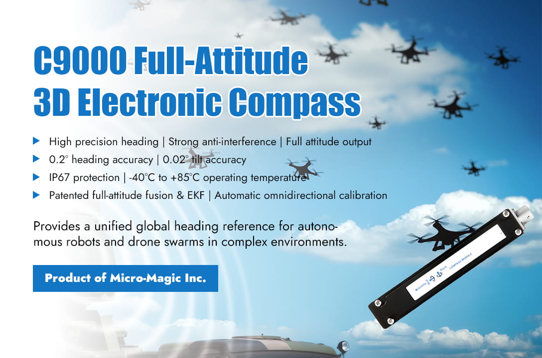
In today's era where autonomous systems' collaborative operations are becoming increasingly prevalent, providing stable and unified global navigation reference for distributed robotic clusters has always been a key technical challenge. Recently, the C9000 series high-precision six-axis full-attitude electronic compass developed by Micro-Magic Inc was successfully integrated into the next-generation cluster control system of a leading high-end drone system integrator. This integration offers a highly reliable directional benchmark for multi-vehicle cooperative navigation, significantly enhancing the system's overall navigation accuracy and coordination capabilities in complex environments. In the "Intelligent Inspection Drone Group" project, multiple drones are required to conduct collaborative inspections at the wind power plant. The task requires each drone to maintain a consistent heading coordinate system and accurately synchronize and position complex structures such as wind turbine blades and towers. Traditional single point magnetic compasses are susceptible to electromagnetic interference from wind turbine steel structures, leading to heading deviation and subsequently affecting cluster path planning and data fusion. By carrying the C9000 series full attitude electronic compass, each drone can output high-precision three-axis attitude data of heading, pitch, and roll in real time, and effectively suppress interference from strong magnetic environments on site through built-in hard magnetic, soft magnetic, and tilt compensation algorithms. The C9000, with its 0.2 ° heading accuracy and 0.02 ° tilt accuracy, can provide stable attitude output even during large maneuvers of the drone. Its patented full attitude fusion algorithm and extended Kalman filtering technology ensure high data refresh rate and real-time performance during dynamic flight. In addition, the product supports IP67 protection level, with a working temperature range of -40 ℃ to+85 ℃, suitable for harsh outdoor and high-altitude environments, ensuring reliable operation of the system under various weather conditions. The technical leader of the project stated, "The C9000 series not only provides us with precise heading benchmarks, but its multi interface support and flexible calibration modes also greatly simplify the system integration and on-site debugging process. We have significantly improved the environmental adaptability of the cluster system in different wind farms by using its automatic omnidirectional calibration function to quickly calibrate each drone on site before deployment". With the continuous expansion of applications such as autonomous driving, drone formation, and robot collaborative operations, high-precision and strong anti-interference full attitude heading sensors are becoming one of the core components for achieving true "cluster intelligence". The C9000 electronic compass provides a unified, stable, and reliable global heading reference, laying the technical foundation for coordinated operations of multi-agent systems in complex real-world scenarios. It is expected to play a more critical role in unmanned systems, industrial inspection, terrain mapping, and even emergency rescue. C9000-A C9000-B C9000-C
Read More
In the field of high-precision directional measurement, fiber optic gyroscopes and laser gyroscope north finders have long dominated. Although they have considerable accuracy, their large size, high power consumption, and expensive manufacturing costs make it difficult for many applications that are sensitive to weight, power supply, and budget to truly enjoy high-precision north finding services. The emergence of NF1200 high-precision MEMS north finder launched by Micro-Magic Inc is attempting to break this situation. The first characteristic of this product is small . The external dimensions of NF1200 are only 47×47×35.5mm, weighing about 100 grams, with a steady-state power consumption of no more than 2 watts and a startup time of no more than 2 seconds. In contrast, traditional fiber optic north finders typically have a volume of over 100mm, a weight of over 500 grams or even up to 2 kilograms, and power consumption ranging from 5 to 15 watts. This level of difference means that NF1200 can easily be embedded in small unmanned aerial vehicles, individual handheld terminals, small autonomous underwater vehicles, and projectile guidance platforms that are extremely demanding on load and power supply, while fiber optic solutions are almost impossible to achieve. The second characteristic is accuracy. Many people's impression of MEMS gyroscopes still remains at the stage of low precision and large drift, but the performance parameters of NF1200 have overturned this cognition. The zero bias instability of its MEMS gyroscope is better than 0.02°/h, and the angle random walk is better than 0.01°/√ h. The system level self north finding accuracy reaches ≤ 0.5°secL (L represents local latitude), and the attitude accuracy is better than 0.05°. This means that NF1200 has reached the same level of north finding accuracy as fiber optic solutions, truly achieving high-precision north finding tasks that were previously only possible with optical gyroscopes using MEMS technology. The third characteristic is stability. NF1200 provides complete compensation for zero position, scale factor, non orthogonal errors, and acceleration related errors within the range of -40°C to +80°C, and can withstand 500g shock and 6.06g random vibration. This enables it to maintain stable and reliable high-precision north finding performance even in harsh environments such as mines, vehicles, drilling, and launch overload. The fourth characteristic is "cost-effectiveness." The NF1200 achieves 100% domestic production of its components, with batch production costs ranging from approximately 30% to 50% of those of fiber optic north finders with the same accuracy. Additionally, it supports configurable north-seeking time and installation error angle correction, reducing the difficulty of integration and maintenance for users. This makes high-precision north seeking no longer exclusive to expensive equipment, but a practical technology that can be deployed on a large scale. In GPS-denied environments with strong magnetic interference, the NF1200 leverages its excellent performance, compact size, and low power consumption to provide a reliable true north reference for various scenarios such as mine orientation, measurement while drilling (MWD), pipeline inspection, individual soldiers, and unmanned vehicles. This enables high-precision MEMS north finding to truly move toward practical engineering applications.
Read More
Flux gate sensors and Hall effect magnetic sensors are both devices used to measure magnetic fields, but they have significant differences in principle, performance, and application scenarios. Flux gate sensors are based on the nonlinear magnetization characteristics of magnetic core materials. By exciting the magnetic core with high-frequency alternating current, the saturation characteristics of the magnetic core will change when an external magnetic field exists, resulting in the second harmonic component of the induced voltage (related to the strength of the external magnetic field). Flux gate sensors require complex coil structures and signal processing circuits (such as oscillators and demodulation circuits). Hall effect sensors are based on the Hall effect. When current passes through a conductor or semiconductor, a magnetic field perpendicular to the direction of the current will deflect the charge carriers, generating a transverse voltage (Hall voltage). The Hall voltage is directly proportional to the magnetic field strength and current magnitude. Hall effect sensors have a simple structure, typically consisting of semiconductor materials such as gallium arsenide, silicon, etc., and integrated with signal conditioning circuits. The magnetic flux gate sensor has high sensitivity, it can detect extremely weak magnetic fields (as low as nanotesla level, nT), suitable for measuring the Earth's magnetic field (about 30-60 μT). Hall effect sensors have low sensitivity, they are typically used for magnetic field measurements above the millitesla (mT) level, and some high-sensitivity models can reach micro tesla (μT). The accuracy is greatly affected by temperature, and a temperature compensation circuit is needed to improve stability. Flux gate sensors require high-frequency excitation signals and complex circuits, with high power consumption (usually in the milliwatt range). Not suitable for battery powered portable devices. Hall effect sensors have low power consumption (micro watt level), especially digital output types (such as switch mode Hall sensors). Suitable for low-power applications such as mobile phones and smart devices. Therefore, it is necessary to select flux gate sensors for detecting weak magnetic fields (such as geomagnetic navigation, scientific instruments). Low cost, low-power, high-frequency response (such as motor control, consumer electronics) are required to choose Hall effect sensors.
Read More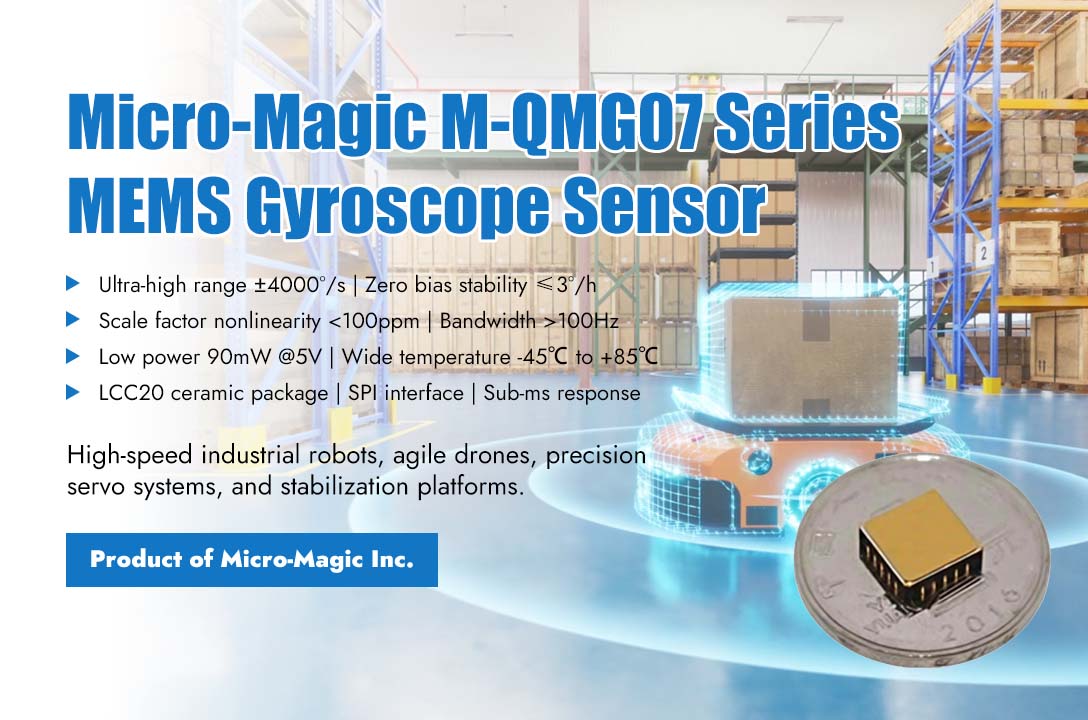
Amid the rapid development in industrial automation, drone, and robotic control, systems have imposed unprecedented stringent requirements on motion sensing devices. Traditional gyroscopes often face technical bottlenecks such as insufficient range, reduced accuracy, and delayed response in ultra-high-speed and high-dynamic motion scenarios, becoming a critical factor limiting the performance breakthrough of high-end equipment. Recently, Micro-Magic officially launched the M-QMG07 series single-axis MEMS gyroscope. With its ultra-large dynamic range of up to ±4000°/s and exceptional bias stability of ≤3°/h, it has opened a new technical landscape for high-speed, high-precision motion control. The core breakthrough of the M-QMG07 series lies in its integration of an extremely wide range coverage with military-grade measurement accuracy. This series offers multiple range options from ±500°/s to ±4000°/s, enabling comprehensive capture of angular motion across the full spectrum—from micro-oscillations in precision instruments to intense maneuvers of high-speed aircraft. Crucially, while achieving such an ultra-wide range, it maintains industry-leading precision metrics: zero bias stability of better than 3°/h at room temperature, a scale factor nonlinearity below 100ppm, and outstanding performance across the full temperature range, ensuring stable and reliable data output even under complex thermal and vibration conditions. This series of gyroscope sensors has brought revolutionary improvements to applications such as high-speed industrial robots, high-end servo systems, highly maneuverable drones, and precision stabilization platforms. For example, when high-speed parallel robots perform sorting and packaging tasks, the joint acceleration of the robotic arm is extremely high, and traditional gyroscopes are prone to signal truncation due to range limitations, which can lead to control oscillations and even instability. The ultra large range of M-QMG07 can respond to instantaneous angular velocity changes of up to thousands of degrees per second without distortion, providing a real and continuous data foundation for real-time motion planning and vibration suppression. At the same time, its high zero bias stability significantly reduces attitude drift during long-term operation, helping to achieve higher repeat positioning accuracy and job consistency. In the field of drones, whether it is the extreme yaw of racing models on bends or the rapid stabilization of industry drones in strong turbulence, extreme requirements are placed on the range and dynamic response of gyroscopes. The M-QMG07 can not only fully capture instantaneous angular velocities of ±4000°/s, but its bandwidth can be configured to be above 100Hz, with sub-millisecond response capability, ensuring that the flight control system can perceive and compensate for every high-frequency disturbance in real time, greatly improving flight stability, control accuracy, and resistance to environmental interference. To achieve such outstanding performance, M-QMG07 adopts a full silicon MEMS capacitive sensing structure and customized low-power signal processing ASIC, with a typical power consumption of no more than 90mW under a 5V power supply. The product adopts a sturdy LCC20 ceramic package, with excellent resistance to mechanical shock and vibration characteristics, and supports wide temperature operation from -45℃ to +85℃. Through the standard SPI interface and programmable filters, users can flexibly configure data output modes and bandwidth, achieving system level noise optimization and dynamic performance adjustment. At present, the M-QMG07 series can provide engineering samples and comprehensive technical support. With the gradual introduction of this chip in multiple fields, the technological boundaries of high-speed motion control are expected to be further expanded, empowering the next generation of intelligent systems to achieve more agile, precise, and stable motion performance.
Read More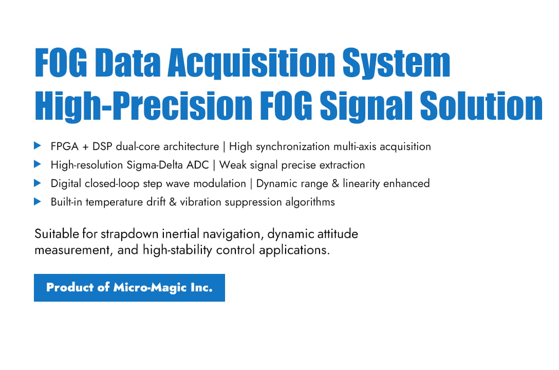
The design of the fiber optic gyroscope data acquisition system focuses on how to extract weak angular velocity signals from noise and achieve high-precision, high-synchronization digital conversion. The current mainstream technical approach adopts the "FPGA+DSP" architecture to meet the requirements of front-end high-speed data acquisition and back-end complex signal processing. The overall system architecture typically consists of four layers: sensor front-end, signal conditioning and acquisition, core data processing, and communication and power management. For a triaxial integrated system, it is necessary to synchronize the acquisition of signals from three orthogonal directions. In terms of hardware design, the front end uses a precision signal conditioning circuit (amplification, level shifting) to match the ADC input range. A high-resolution Sigma-Delta ADC is selected to ensure accurate weak signal acquisition. An FPGA is responsible for multi-axis synchronous triggering and digital demodulation, while a DSP performs closed-loop control, error compensation, and strapdown inertial navigation algorithm. The communication interfaces support RS-422, CAN, etc., and include a PPS (pulse per second) synchronization function. In terms of software algorithms, a digital closed-loop step wave modulation technique is adopted, where feedback phase is applied via a Y-waveguide to significantly improve dynamic range and linearity. Meanwhile, algorithms such as dynamic voltage compensation, vibration suppression, and reference channel noise reduction are integrated to effectively eliminate temperature drift and light source intensity noise. The data processing flow includes initialization calibration, synchronous sampling, computation compensation, and integral output, and the final data is packaged according to the communication protocol and transmitted to the host computer. The system design balances high precision, high synchronization, and strong anti-interference ability, making it suitable for navigation application scenarios that require strict dynamic response and stability.
Read Moreleave a message
Scan to Wechat :
