




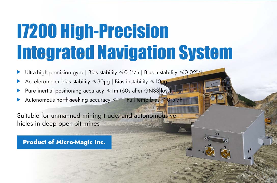
At the bottom of an open-pit mine with a depth of over 200 meters, towering rock walls surround it on all sides. A 300 ton unmanned mining truck is carrying out stripping operations, but it is facing the dilemma of severe satellite signal obstruction: GPS signals are intermittent, RTK fixed solutions are frequently degraded, ordinary integrated navigation systems can produce enough drift to deviate from the lane within a few minutes, and the mining truck has deep mining areas on one side and hard rock walls on the other. Any positioning deviation may cause serious accidents. This is the core scenario in which the I7200 high-precision integrated navigation system produced by Micro-Magic Inc is designed - how to rely on the combination of inertia and odometer to maintain lane level positioning accuracy for unmanned vehicles in an environment where satellite signals are systematically rejected. The confidence of I7200 first comes from its ultra-high precision gyroscope. In pure inertial mode after the disappearance of GNSS signals, most MEMS integrated navigation systems accumulate several meters of lateral error within sixty seconds, which is sufficient for mining trucks to deviate from the lane. The gyroscope of I7200 achieves zero bias stability of ≤ 0.1 °/h, zero bias instability of ≤ 0.02 °/h, and angle random walk of ≤ 0.01 °/√ h. This means that within 60 seconds without satellite signals, its heading drift is controlled within 1°. With the zero bias stability of ≤ 30μg and the zero bias instability of ≤ 10 μg of the accelerometer, the system can accurately perceive every pitch and roll of the vehicle on bumpy roads, and convert these small movements into accurate displacement calculations. By integrating external information such as odometry and kinematic constraint algorithms, the I7200 achieves a pure inertial positioning accuracy of ≤1 meter within 60 seconds after GNSS signal loss. This level of accuracy is just within the safety margin for maintaining lane keeping on mining trucks. The self-north-seeking capability is another underestimated yet critical feature. The I7200 supports autonomous north-seeking with an accuracy of ≤1°, allowing mining trucks to complete heading initialization while stationary without any additional operations. For mining trucks that rotate among multiple vehicles, this feature significantly simplifies the deployment process. On a deeper level, the design logic of I7200 responds to a core contradiction in the industrialization of autonomous driving: high-precision sensors have superior performance but high cost, while low-cost sensors lack reliability in complex environments. The I7200 benchmarks fiber optic gyroscope grade products in key indicators of gyroscopes and accelerometers - with a full temperature zero bias of ≤ 0.5 °/h and an accelerometer full temperature zero bias of ≤ 1mg - while maintaining the low cost and small size advantages of MEMS solutions. The size of 93mm×85mm×49.5mm and the weight of less than 500 grams allow it to be flexibly installed in the cab or protective box of the mining truck, and the steady-state power consumption of 4W does not even require separate consideration of heat dissipation design. This is the value that I7200 brings to autonomous driving: not to make the vehicle fly faster under ideal conditions, but to let it know where it is in the most dangerous moments.
Read More
The indirect calculation of heading angle through wheel speed difference is a simplified version of the classic "wheel speed odometer" method in vehicle dynamics. The core principle is to use the speed difference between the left and right wheels, combined with the vehicle's wheelbase, to calculate the angular velocity of the vehicle rotating around the vertical axis, and integrate it to obtain the heading angle. The specific implementation method is as follows: (1) Calculate instantaneous yaw rate based on the linear velocity of the left and right wheels Read the left rear wheel speed and right rear wheel speed (unit: rad/s), and calculate the linear velocity of the left and right wheels based on the wheelbase L (unit: m) and tire rolling radius r (unit: m): ; ; Directly using this formula will face many practical problems in reality, and algorithm level correction of steering geometry and compensation for sideslip and nonlinear regions are also required. Steering geometry correction (Ackermann steering geometry) typically uses the wheel speed of the non steering axis (usually the rear axle) to calculate the rate of change in heading angle. Side slip and nonlinear compensation usually involve the fusion of wheel speed difference calculation with IMU (Inertial Measurement Unit) gyroscope data (such as Kalman filtering), using wheel speed difference to correct the gyroscope's zero bias drift, and using the gyroscope to compensate for the dynamic delay of wheel speed calculation. (1) Signal processing When driving at low speeds, the speed difference between the left and right wheels is very small. If the resolution of the wheel speed pulse counter is insufficient, it will cause the calculated heading angle change rate to jump severely. Low pass filtering is required to remove high-frequency noise using first-order low-pass filtering. (2) Integrating to calculate heading angle In this way, high-precision estimation of heading angle change rate can be obtained solely through wheel speed sensors under low-speed and quasi-static conditions, which is of great value for short-term positioning and Dead Reckoning.
Read More
Precision machine tools are the "industrial mother machines" of modern manufacturing, with their machining accuracy directly determining the quality and performance of components. The leveling status of the machine tool serves as the fundamental prerequisite for ensuring this accuracy. Whether in large gantry milling machines, five-axis machining centers, or high-precision grinders, minor foundation settlement, thermal deformation from ambient temperature changes, and the cumulative effects of operational vibrations can all cause the machine table to deviate from its ideal level state. The T7000F series full temperature compensation ultra-high precision dual-axis tilt sensor developed by Micro-Magic Inc has demonstrated excellent application value in the field of precision machine tool horizontal control with its resolution of 0.0005 ° and maximum full temperature range accuracy of 0.001 °. In the industrial application of precision machine tool horizontal control, the value of T7000F is reflected in two key links: equipment installation and commissioning, and operation status monitoring. During the installation phase of the machine tool, T7000F is installed on the key measuring points of the machine tool bed. Multiple sensors are networked through RS485 or CAN bus to obtain real-time absolute tilt values of each measuring point, greatly improving installation and debugging efficiency and accuracy. For large gantry machine tools, the dual axis simultaneous measurement feature can simultaneously monitor the angle changes in both roll and pitch directions, ensuring that the guide rail maintains horizontal consistency throughout the entire length range. During the operation phase of the equipment, sensors are integrated into the machine tool control system for a long time, which can monitor changes in the horizontal state in real time. When the tilt value exceeds the set threshold, it will automatically alarm or cooperate with the automatic leveling device to achieve closed-loop control, effectively preventing batch processing quality accidents caused by changes in machine tool posture. The excellent anti-vibration and anti-shock performance of T7000F sensor is crucial in machine tool applications. Machine tools will generate continuous vibration during high-speed cutting, especially in intermittent cutting processes such as milling and grinding, with complex vibration spectra and high acceleration peaks. T7000F has an shock resistance of over 20000g and a vibration resistance of 10grms, and can be stably installed on the machine bed or worktable for long-term reliable operation. Its IP67 protection level, combined with an aluminum alloy oxidation shell, is sufficient to resist the erosion of cutting fluid, oil mist, and metal dust. In terms of communication interface, the sensor supports multiple bus options such as RS232, RS485, CAN, etc., making it easy to integrate with various CNC systems or PLCs and connect to industrial fieldbus networks without additional protocol conversion. As the manufacturing industry accelerates its evolution toward high-end applications, the demands on foundation accuracy for precision machine tools continue to rise. With its full-temperature-range high precision, strong anti-interference capability, and flexible integration options, the T7000F provides a professional and reliable technical solution for level control in precision machine tools.
Read More
Inaccurate measurement of the lever arm between IMU (Inertial Measurement Unit) and GNSS (Global Navigation Satellite System) antennas is a common source of error in GNSS/INS integrated navigation systems. This error significantly affects the accuracy of integrated navigation under dynamic conditions, especially during rotational motion. Usually, the following methods are used to compensate for the errors in the integrated navigation system caused by the influence of the lever arm. 1. Offline Calibration: Before the system is put into use, the lever arm vector is accurately estimated through specific testing maneuvers. Usually, static multi position method and dynamic maneuver method ("8" or snake maneuver) are used. If the maneuvering design is appropriate and the data quality is high, very accurate estimates of the lever arm can be obtained. 2. Online Estimation: During the operation of a integrated navigation filter (usually a Kalman filter or its variants such as EKF, UKF), the lever arm vector is used as part of the state variable for real-time estimation. It does not require additional offline testing and can gradually correct lever arm errors during normal system operation. 3. Adaptive/Robust Filtering: When the arm error cannot be accurately known and the online estimation effect is poor (such as insufficient carrier mobility), adjusting the filter parameters can tolerate or weaken the influence of arm error, prevent filter divergence, or provide overly optimistic accuracy evaluation. It is recommended to prioritize offline calibration. If conditions permit, conducting specialized dynamic maneuvering calibration is the best method to obtain high-precision lever arm values. Secondly, online estimation is implemented to estimate the lever arm vector as a state variable in the integrated navigation filter. This is the most commonly used and effective real-time processing method in engineering practice. Be sure to ensure that the carrier has sufficient rotational maneuverability to make the lever arm observable. Finally, combining adaptive/robust strategies to prevent severe performance degradation or divergence.
Read More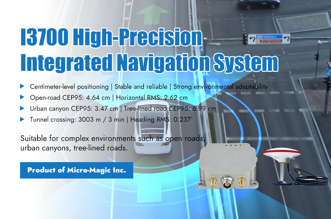
To fully verify the performance of the I3700 integrated navigation system in real-world application scenarios, Micro-Magic Inc conducted a comprehensive and rigorous product performance test in response to customer requirements. The testing covers six typical scenarios including open roads, urban canyons, tree-lined roads, underground garages, long tunnels, and elevated auxiliary roads, comprehensively evaluating the positioning accuracy and stability of the system in various complex environments. This test uses the NovAte PwrPak7D-E1 high-precision integrated navigation system as the true value reference, and uses Waypoint Inertial Explorer professional software for post-processing and smoothing calculations to ensure the high reliability and centimeter level accuracy of the test data. The test results show that in an open environment with good satellite signals, the I3700 has a CEP95 (95% positioning error) of only 4.64 centimeters and a horizontal RMS error of 2.62 centimeters. The system availability is as high as 100%, achieving true centimeter level positioning. In environments with severe signal obstruction such as urban canyons and tree-lined roads, I3700 still performs robustly, with CEP95 reaching 3.47 cm and 6.99 cm respectively, and horizontal RMS error controlled at 1.79 cm and 4.77 cm, fully demonstrating its strong multipath suppression and signal recovery capabilities. In the more challenging scenario of complete loss of GNSS signal lock, the pure inertial navigation performance of I3700 becomes the biggest highlight. In the high-speed tunnel crossing test that lasted for about 3 minutes and was 3003 meters long, the system's horizontal positioning RMS was 4.28 meters, speed RMS was 6.57 centimeters per second, and heading angle RMS remained stable at 0.237 °, fully demonstrating its excellent drift control capability in long-term, high dynamic GNSS denial environments. The I3700 integrated navigation system integrates high-performance MEMS-IMU and full constellation, full frequency dual antenna RTK GNSS receiver. The gyroscope has a zero bias instability of 1.6°/h and the accelerometer has a zero bias instability of 18 μ g; RTK positioning accuracy can reach 1 centimeter, and dual antenna direction finding accuracy is 0.2° (1-meter baseline); Achieving 100% availability in open environments, maintaining high-precision output even in signal occlusion and loss of lock scenarios, suitable for various high-end application scenarios such as drones, unmanned ships, autonomous driving, agricultural machinery, and satellite communication antenna stabilization platforms. Micro-Magic Inc stated that the I3700 integrated navigation system demonstrated excellent comprehensive performance in this rigorous test, not only achieving centimeter level positioning in open environments, but also maintaining stable and reliable pose output under extreme conditions of GNSS signal loss with powerful inertial navigation algorithms. Its excellent environmental adaptability and positioning accuracy fully meet the urgent demand of current intelligent equipment for high-precision and high reliability navigation systems.
Read More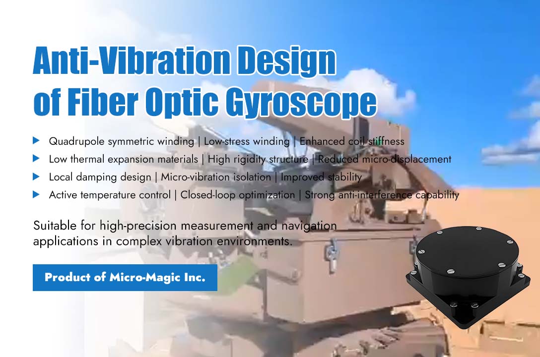
The anti-vibration design of fiber optic gyroscope is a typical engineering optimization problem that requires collaborative efforts in mechanical structure, optical path design, and signal processing. The current mainstream solution is to physically isolate vibrations, suppress error sources on the optical path, and filter out residual noise through algorithms, thus forming a complete anti-vibration system. At the light source and fiber coil level, the design of the fiber coil is optimized by employing quadrupole symmetric winding, low-stress winding techniques, and optimizing adhesive selection and curing processes to enhance the coil's stiffness and resistance to deformation. At the internal structure design and packaging level, materials with low thermal expansion coefficients and high rigidity (such as ceramics and invar) are used to fabricate the coil skeleton and optical bench, and the mounting methods of optical components (light source, coupler, modulator, detector) are optimized to reduce micro-displacement. Simultaneously, local damping structures (such as rubber pads, silicone filling) or micro-vibration isolators are designed around key sensitive internal components of the gyroscope (such as the fiber coil). At the signal processing level, active temperature control is used to stabilize the temperature of the light source and key optical components, thereby reducing temperature drift. Closed-loop feedback control is optimized to enhance the stability and anti-interference capability of the control loop. Digital filtering techniques, such as notch filters or adaptive filters designed for specific vibration frequencies, are employed to suppress vibration noise during signal processing. Additionally, through error modeling and compensation, a mathematical model (e.g., polynomial, neural network) relating vibration (acceleration, frequency) to output error is established to enable real-time compensation in the output.
Read More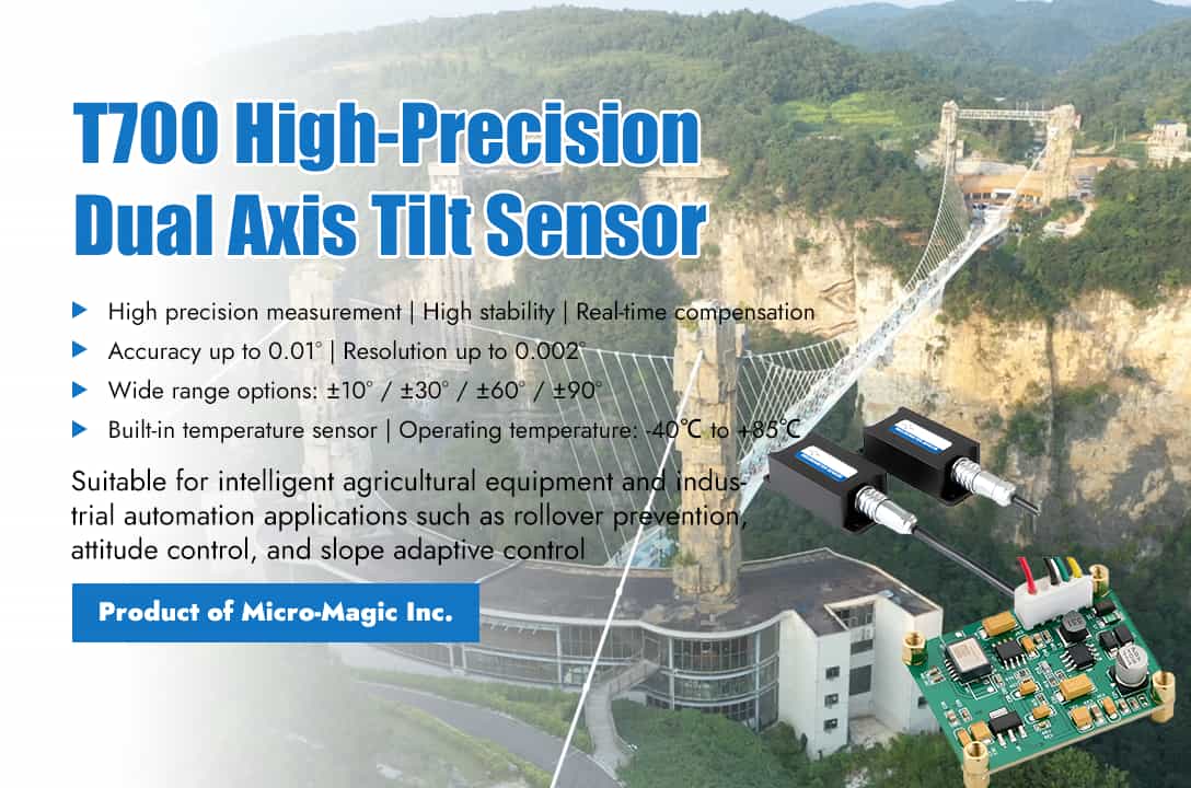
With the continuous improvement of agricultural machinery automation level, the requirements for equipment posture perception, safety control, and operational accuracy are also increasing. Micro-Magic Inc has launched the T700 series high-precision dual axis tilt sensor designed specifically for industrial control scenarios, providing a highly reliable and cost-effective attitude sensing solution for the field of agricultural machinery automation. The technical core of the T700 series comes from ADI's high-precision digital sensors, combined with Micro-Magic's independently developed n-order filtering algorithm and 16 bit A/D converter, to achieve real-time and accurate measurement of X-axis and Y-axis tilt angles. Its core technical indicators are impressive: full range accuracy up to 0.01°, resolution up to 0.002°, zero bias temperature drift not exceeding 0.008°/℃, sensitivity temperature coefficient controlled within 100ppm/℃, supporting multiple range options such as ± 10°, ± 30°, ± 60°, ± 90°, etc., which can meet the needs of different application scenarios. Of particular note is that the T700 series has a built-in temperature sensor that monitors real-time temperature changes in the working environment and dynamically compensates for sensor outputs through algorithms, ensuring high repeatability and stability of measurement data within a wide temperature range of -40℃ to +85℃. This feature has extremely high practical value for agricultural work environments with large temperature differences between day and night and obvious seasonal changes, ensuring that the equipment can provide reliable angle data under any climate conditions. The T700 series products can output various digital signals such as RS232, RS485, RS422, Modbus, and CAN, as well as analog signals like current and voltage. They are available in diverse forms, including complete units with a housing and bare boards without a housing. Additionally, slim-structure products suitable for confined spaces can be provided to meet special requirements. This facilitates system integration and easy installation for customers. With the continuous improvement of agricultural machinery automation level, the requirements for equipment posture perception, safety control, and operational accuracy are also increasing. Micro-Magic Inc has launched the T700 series high-precision dual axis tilt sensor designed specifically for industrial control scenarios, providing a highly reliable and cost-effective attitude sensing solution for the field of agricultural machinery automation. The technical core of the T700 series comes from ADI's high-precision digital sensors, combined with Micro-Magic's independently developed n-order filtering algorithm and 16 bit A/D converter, to achieve real-time and accurate measurement of X-axis and Y-axis tilt angles. Its core technical indicators are impressive: full range accuracy up to 0.01°, resolution up to 0.002°, zero bias temperature drift not exceeding 0.008°/℃, sensitivity temperature coefficient controlled within 100ppm/℃, supporting multiple range options such as ± 10°, ± 30°, ± 60°, ± 90°, etc., which can meet the needs of different application scenarios. Of particular note is that the T700 series has a built-in temperature sensor that monitors real-time temperature changes in the working environment and dynamically compensates for sensor outputs through algorithms, ensuring high repeatability and stability of measurement data within a wide temperature range of -40℃ to +85℃. This feature has extremely high practical value for agricultural work environments with large temperature differences between day and night and obvious seasonal changes, ensuring that the equipment can provide reliable angle data under any climate conditions. The T700 series products can output various digital signals such as RS232, RS485, RS422, Modbus, and CAN, as well as analog signals like current and voltage. They are available in diverse forms, including complete units with a housing and bare boards without a housing. Additionally, slim-structure products suitable for confined spaces can be provided to meet special requirements. This facilitates system integration and easy installation for customers. The T700 series provides technical support for the following typical scenarios through real-time perception and data output of device posture. ² Dump Truck Rollover Prevention Monitoring: T700 can monitor the tilt angle of the X-axis and Y-axis during the lifting process of the carriage in real time. When the tilt angle exceeds the set threshold, the system can trigger an audible and visual alarm or automatically interrupt the lifting action, effectively preventing rollover accidents caused by load deviation or uneven ground. ² Excavator Attitude Control: T700 can simultaneously monitor the horizontal posture of the fuselage and the tilt angle of the boom moving parts, providing real-time feedback data for the electronic control system. ² Slope Speed Adaptive Control: T700 can output the real-time tilt angle of the vehicle relative to the horizontal plane, and with the help of the vehicle control system, achieve speed adaptive adjustment based on slope. In the wave of integration between precise perception and intelligent decision-making, the Micro-Magic's T700 series tilt sensor, with its high reliability and flexible product form, has equipped agricultural machinery and equipment with "nerve endings" that can perceive terrain. This is not only a technological upgrade, but also a solid step towards digitalization and intelligence of agricultural productivity.
Read More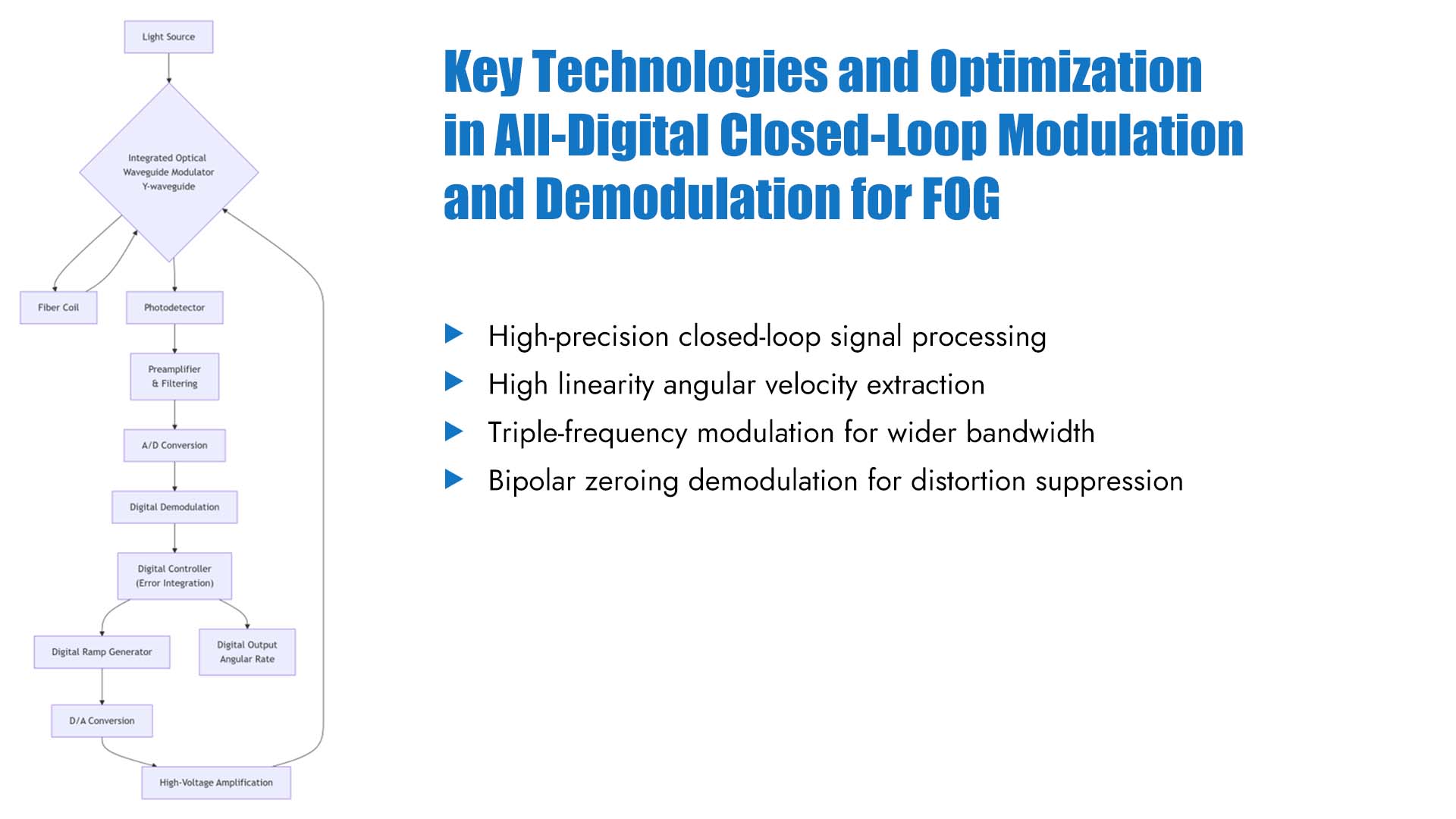
The fully digital closed-loop modulation and demodulation scheme is currently the mainstream technology for high-precision interferometric fiber optic gyroscopes (IFOGs). It modulates and demodulates optical signals under closed-loop conditions through digital circuits, thereby extracting rotational angular velocity with high linearity. A typical fully digital closed-loop signal processing system diagram is shown in the figure below, with key technologies and optimizations including system bandwidth improvement, modulation distortion suppression, and hardware platform implementation. Improvement of System Bandwidth By adopting a triple frequency modulation/demodulation scheme, the sampling period is shortened to one-third of the fundamental frequency scheme, significantly increasing the system bandwidth and better compensating for high-frequency noise signals, improving dynamic performance without affecting static accuracy. Suppression of Modulation Distortion This method adopts a bipolar zeroing pulse square wave demodulation method, which can effectively eliminate or suppress the influence of modulation distortion. Compared to conventional demodulation methods, this technique can reduce the relative error of measuring angular velocity by an order of magnitude (from 1% to 0.1%), which is of great significance for improving the measurement accuracy and stability of closed-loop gyroscopes. Implementation of Hardware Platform All-digital closed-loop schemes typically rely on high-performance digital signal processing platforms. Due to its strong parallel processing capability, high integration, and good flexibility, FPGA has gradually become the mainstream choice. FPGAs can perform all digital demodulation, timing logic control, digital filtering, and even some preprocessing functions. The all-digital closed-loop modulation and demodulation scheme achieves linear extraction of FOG signals through the synergistic operation of phase modulation biasing, digital correlation demodulation, and stepped-wave phase feedback. This scheme is not only key to achieving high precision and a large dynamic range in FOG, but also its adaptability in high-dynamic environments and its level of integration are constantly being improved.
Read More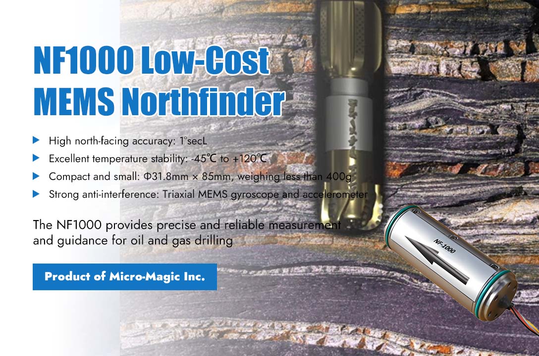
The precise control of directional drilling relies on three key parameters: inclination angle (how much the borehole is tilted), azimuth (the geographic direction the borehole faces), and tool face angle (the orientation of the directional tool). Even minor deviations in these angles can accumulate with increasing well depth, leading to significant trajectory deviations, resulting in millions of dollars in economic losses or even safety incidents. The NF1000 MEMS northfinder introduced by Micro-Magic Inc, with its advantages of low cost, compact size, high precision, and resistance to harsh environments, serves as a crucial solution to this challenge. NF1000 adopts high-performance MEMS gyroscope and accelerometer, with excellent full temperature calibration capability (-45℃ to +120℃), which can maintain stable output even in extreme underground environments. Its north finding accuracy is as high as 1°secL (L represents latitude), and its horizontal attitude accuracy is better than 0.15 °, meeting the high requirements for directional drilling in oil and gas drilling. In addition, traditional north finding equipment is often bulky and complex to install, while the NF1000 has a size of only Φ31.8mm × 85mm and weighs less than 400g, making it easy to integrate into narrow spaces such as drill rods and tunneling machines, greatly reducing installation barriers and renovation costs. In the specific application of directional drilling, NF1000 is firmly installed in the measuring short section of the downhole drilling tool assembly. If there is a fixed angle between the X-axis of NF1000 and the direction of the drill bit, the system will perform coordinate axis conversion to ensure that the output wellbore inclination angle and azimuth angle fully correspond to the true posture of the drilling tool. During the drilling process, the NF1000's built-in three-axis MEMS gyroscope continuously senses the angular velocity of the drilling tool, while the three-axis accelerometer senses the gravitational acceleration component. Real time calculation of three key data points through internal navigation algorithms: (1) Well inclination angle: ranging from 0° to 180°, used to determine whether the wellbore is vertical, inclined, or horizontal. (2) Azimuth: The angle from clockwise rotation from true north to the horizontal projection line of the wellbore determines the plane direction of drilling. (3) Tool face angle: divided into gravity tool face and gyroscope tool face. This is crucial for directional tilting and adjusting wellbore trajectories in magnetic interference environments. NF1000 represents the leading level of MEMS process inertial devices. On the underground battlefield of directional drilling in oil and gas fields, NF1000 is providing precise, resilient, and reliable guidance for every well, helping engineers reach their targets accurately in the underground maze. NF1000
Read More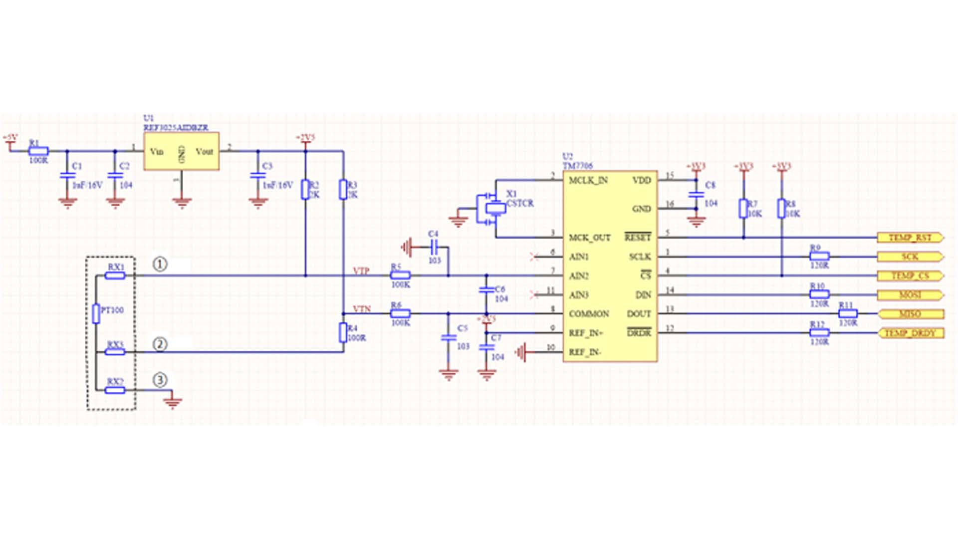
The PT100 resistance thermometer is constructed from pure platinum metal—hence its designation as a platinum resistance thermometer—and stands as the most widely utilized temperature sensor within the medium-to-low temperature range. Its primary characteristics include high measurement accuracy, excellent stability, high reliability, and a long service life. In contrast, thermocouples demonstrate superior performance in high-temperature environments, capable of measuring temperatures reaching as high as 2315°C. The temperature coefficient of platinum resistance is 3.9×10⁻³/°C; at 0°C, its resistance value is 100Ω, and its rate of resistance change is 0.3851Ω/°C. The circuitry typically employed to measure a resistance thermometer is an unbalanced bridge configuration. When the resistance thermometer serves as one of the bridge arms, its connecting lead wires effectively become an integral part of that bridge arm's resistance; since this additional resistance is unknown and fluctuates with ambient temperature, it introduces measurement errors. To eliminate the measurement errors caused by the resistance of these connecting lead wires, a three-wire connection method is commonly adopted. Figure 1 illustrates a three-wire bridge-based sampling and measurement circuit driven by a constant voltage source. The three lead wires extending from the PT100 possess identical cross-sectional areas and lengths, ensuring that their respective lead resistances are equal—specifically, RX1 = RX2 = RX3. One of these wires (RX2) is connected to the bridge's common reference terminal—specifically, the ground terminal—while the remaining two wires (RX1 and RX3) are connected to the bridge arm containing the platinum resistance and the adjacent reference resistance arm, respectively. Through this specific connection scheme, the bridge circuit is able to maintain a balanced state, thereby effectively eliminating the measurement errors attributable to the resistance of the lead wires. In Figure 1 above, resistors R2, R3, and R4, together with the external PT100, form a Wheatstone bridge. The ADC needs only to sample the voltage output of the bridge to calculate the corresponding resistance value of the PT100, thereby deducing the temperature. Under the assumption that lead resistance RX1 equals RX3, the measurement errors introduced by the lead resistances can be effectively cancelled out. The approximate formulas for VT+ and VT- are as follows: VTP = VPT100 + VRX1 + VRX2 VTN = VR4 + VRX3 + VRX2 The voltage difference between points VTP and VTN is: VTP - VTN ≈ VPT100 - VR4 As can be seen, this voltage difference value is independent of the lead resistances; the final voltage difference value can be derived using the following equation: The resistance value of the PT100 can be obtained from the differential pressure value in the above equation.
Read More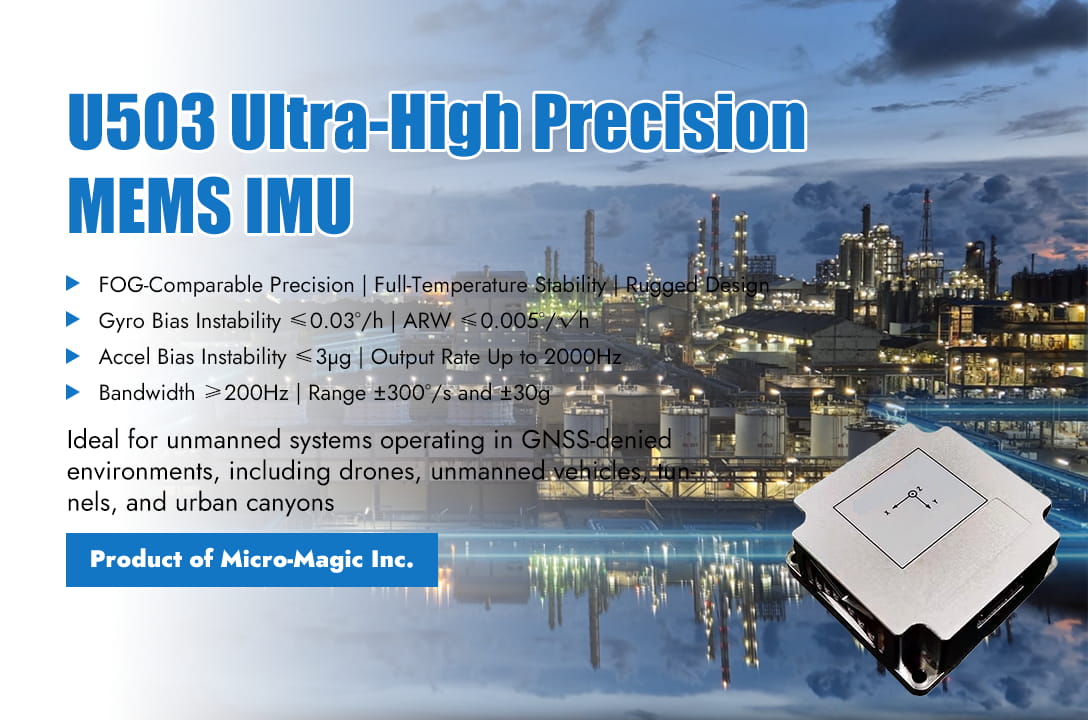
In the field of inertial technology, accuracy has always been the core metric for evaluating IMU value. The U503 series MEMS inertial measurement module introduced by Micro-Magic Inc, with its precision comparable to fiber optic gyroscopes, stable performance across the entire temperature range, and rugged design resistant to harsh environments, plays a pivotal role in the application of unmanned systems. Ultra-High Precision Technical Performance The gyroscope performance of the U503 has reached the top level of MEMS devices, with bias instability (Allan variance) ≤0.03°/h, reflecting the device's stability over long time scales and determining the attitude-holding capability of pure inertial navigation. The angular random walk is ≤0.005°/√h, indicating the extremely low gyroscope noise level of the U503, with an angle error of only about 0.3° after 1-hour integration. The accelerometer of U503 has also reached the top level of industrial grade, with zero bias instability (Allan variance) ≤3μg and excellent long-term stability, supporting high-precision inclination measurement and gravity field modeling. The speed random walk is ≤ 0.01m/s/√ h, and the velocity integration error is extremely low, with a speed error of only about 0.6m/s per hour. U503 is not simply an integration of "gyroscope+accelerometer", but achieves optimal overall performance through system level design. The gyroscope and accelerometer data are strictly aligned, achieving microsecond level delay output and supporting the application scenario of high dynamic integrated navigation. U503 has achieved cross coupling suppression between sensitive axes, with inter axis coupling of ≤0.001rad, ensuring the orthogonality of three-axis measurements and reducing coordinate system conversion errors. At the same time, U503 has built-in self-test and status word output, which can identify and isolate abnormal situations in a timely manner, achieving real-time monitoring of the status. System-Level Assurance Behind Accuracy The ultra-high precision of U503 is not an isolated indicator, but is built on a complete system design. Through full temperature calibration compensation, the zero bias change within the full temperature range is ≤ 20% of the nominal value; Through internal shock-absorbing structure and system sealing design, vibration noise above 1000Hz has been suppressed; By shielding with a metal casing and designing a power filter, EMI interference on analog signals is reduced; Real time output of status words and self check for anomalies to ensure the reliability of output data.. The Core Role of U503 in Unmanned Systems In GNSS/INS integrated navigation systems, IMU provides high-frequency and high-precision relative motion information. The ultra-high precision of U503 extends the survival time when GNSS signals are interrupted. When unmanned vehicles enter tunnels or drones fly over urban canyons and GNSS signals are lost, the system enters pure inertial navigation mode. The position error of 60 second pure inertial navigation is less than 5 meters, and 300 second pure inertial navigation can still maintain meter level positioning . This means that unmanned systems can rely on inertia to maintain navigation capabilities for a longer period of time until the GNSS signal is reacquired or autonomous landing/parking is completed. In underground mining, tunnel construction and other scenarios, the ultra-low drift characteristics of U503 enable it to support the strapdown inertial navigation system to complete pure inertial positioning for tens of minutes, and integrate with odometer/wheel speed meter to achieve sub-meter level positioning accuracy. In scenarios such as drone catapult takeoff, unmanned vehicle collision testing, and missile initial flight, U503 can independently capture the angular velocity and acceleration of the impact process with high bandwidth, and integrate them to obtain attitude changes and velocity trajectories. U503 does not compromise on dynamic performance while pursuing accuracy. Its bandwidth of ≥200Hz covers the vibration frequencies of UAV rotors and the motion frequency bands of unmanned vehicle suspensions, fully preserving dynamic information. The measurement ranges of ±300°/s and ±30g meet the high-maneuverability requirements of most unmanned systems, preventing sensor saturation. With a maximum data update rate of 2000Hz, it provides real-time feedback for high-speed control loops. This enables the U503 to maintain stability at an ultra-high precision level in static scenarios, while accurately capturing intense motion without distortion in high-dynamic scenarios. The U503 series MEMS IMU modules, with their precision comparable to fiber optic gyroscopes, stable performance across the full temperature range, and rugged design resistant to harsh environments, provide unmanned systems with a true "high-precision perception core." U503
Read More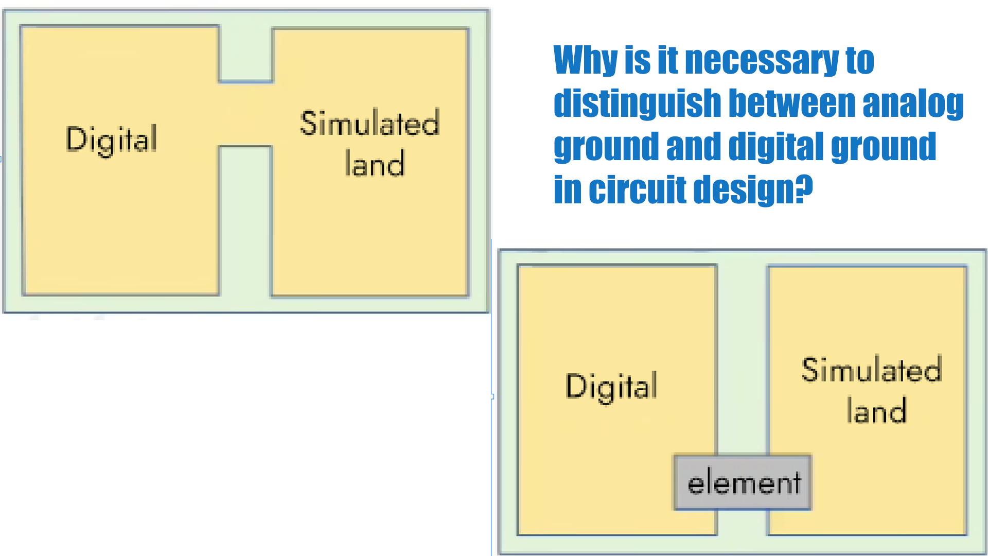
The sensor unit circuits we typically design include both digital signal processing circuits (such as an MCU) and analog circuits (including the front-end sensor and its signal amplification). Simply put, digital ground is the common reference terminal for the digital circuitry, i.e., the reference terminal for digital voltage signals; analog ground is the common reference terminal for the analog circuitry, the voltage reference terminal (zero potential point) for analog signals. Since digital signals are generally rectangular waves with a large number of harmonics, if the digital ground and analog ground on the circuit board are not separated at the connection point, the harmonics in the digital signal can easily interfere with the waveform of the analog signal. When the analog signal is a high-frequency or high-voltage signal, it will also affect the normal operation of the digital circuit. Analog circuits deal with weak signals, but digital circuits have higher threshold levels, so their power supply requirements are lower than those of analog circuits. In systems with both digital and analog circuits, noise generated by the digital circuits can affect the analog circuits, degrading their small-signal performance. To ensure signal integrity and avoid mutual interference, the analog ground and digital ground must be separated. In schematic design, the ground plane of the digital area is labeled DGND, and the ground plane of the analog area is labeled AGND. Then, in PCB design, the ground plane is divided into digital ground and analog ground, with a large distance between them. The digital ground and analog ground should be grounded at a single point, either directly or through component isolation. 1. Direct Connection. As shown in Figure 1, the two are connected at a single point through a wide copper foil. This method is suitable for low-frequency systems or systems that are not sensitive to noise. 2. Component Isolation Connection. As shown in Figure 2, this connection method uses a ferrite bead or a 0-ohm resistor to connect the components. This is a primary connection method. The equivalent circuit of a ferrite bead is similar to a band-stop notch filter, suppressing noise only at a specific frequency. If the frequency range of the noise is known, a ferrite bead is the best choice. A 0-ohm resistor acts as a very narrow current path, effectively limiting the loop current and suppressing noise. Resistors have attenuation effects across all frequency bands (even a 0-ohm resistor has impedance), making a 0-ohm resistor the best choice when the noise frequency range is uncertain.
Read Moreleave a message
Scan to Wechat :
