




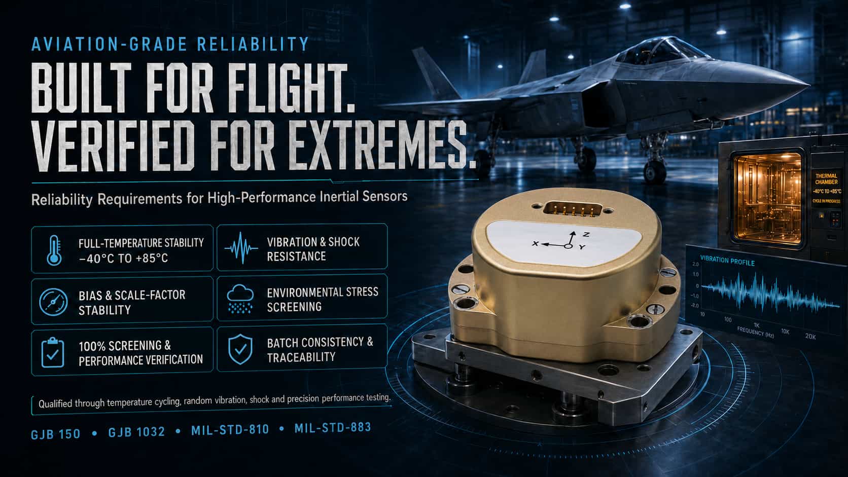
Inertial sensors—including accelerometers, gyroscopes, and inertial measurement units (IMUs)—are core components of navigation, guidance, and control systems in the aviation, aerospace, maritime, and defense sectors; their environmental adaptability and long-term reliability directly determine the operational effectiveness of weapon systems. Military-grade inertial sensors must undergo rigorous Environmental Stress Screening (ESS), where the application of appropriate environmental stresses—such as thermal and mechanical loads—accelerates the manifestation of latent internal defects into failures, allowing for their subsequent elimination. In the international defense and aerospace industries, a comprehensive testing and verification framework for inertial sensors has been established, based on standards such as the US military standards (MIL-STD), ISO, IEEE, and the avionics standard RTCA DO-160. This article examines three key testing categories—high/low-temperature cycling, vibration/shock, and aging screening—analyzing them from the perspectives of both standard frameworks and technical essentials. 1. High/Low-Temperature Cycling Test High/low-temperature cycling tests aim to evaluate the performance stability and structural integrity of inertial sensors when subjected to alternating extreme temperatures. Temperature fluctuations can cause drift in critical parameters—such as sensor bias and scale factor—thereby affecting overall system accuracy. International Standards: MIL-STD-810 outlines procedures for high- and low-temperature exposure tests, covering both operational and storage conditions. Within MIL-STD-883, Method 1010 (Temperature Cycling) specifies "Condition B"—ranging from -55°C to 125°C with up to 100 cycles—while Method 1011 details thermal shock testing procedures. In the avionics sector, Section 5 of RTCA DO-160 specifically regulates temperature variation test procedures. Additionally, ISO 16063-34:2019 specifies sensitivity testing methods at fixed temperatures from the perspective of sensor calibration, covering a range from -190°C to 800°C. Technical Essentials: Key parameters for temperature cycling tests include the temperature range (e.g., -55°C to +85°C or +125°C), rate of temperature change, dwell time, and the number of cycles. In practical testing, conditions typically involve a temperature range of -55°C to +85°C, a 30-minute dwell time, and a temperature change rate of 5–10°C/min. Selecting the appropriate rate is critical: an excessively high rate may exceed the device's thermal inertia limits, leading to false failures, while an excessively low rate may fail to effectively reveal defects. Regarding performance evaluation, parameters such as bias stability and scale factor repeatability must be measured after cycling; for instance, a specific inertial navigation system requires the attitude angle output error to be ≤0.15° across the -55°C to +85°C range. MIL-STD-810 emphasizes tailoring test profiles based on the platform type (e.g., fixed-wing aircraft, rotorcraft, vehicles). 2. Vibration and Shock Testing Vibration and shock tests simulate the mechanical environments experienced by inertial sensors during launch, flight, landing, and transportation, verifying their structural integrity and output accuracy under dynamic loads. International Standards: MIL-STD-810 Method 514 (Vibration) and Method 516 (Shock) serve as the core standards in this field. Method 514.7 specifies procedures and spectral density requirements for random vibration testing (e.g., 25 grms, 10-hour random vibration test). MIL-STD-202 Method 213 outlines mechanical shock test procedures (e.g., 50 g, 11 ms half-sine pulse). The ISO 16063 series provides the methodological basis for vibration and shock sensor calibration: Part 21 covers vibration calibration via reference sensor comparison; Part 22 covers shock calibration; and Part 43 covers accelerometer calibration based on model parameter identification. RTCA DO-160 Section 8 covers sinusoidal and random vibration in the 5 Hz to 2000 Hz range. Technical Highlights: Vibration testing generally encompasses two modes: sinusoidal sweep and random vibration. The power spectral density for random vibration must be tailored to the platform type—for example, requiring a spectral density of 0.04 g²/Hz across the 20 Hz to 2000 Hz range. Shock testing typically employs half-sine pulses, with characteristic parameters including peak accelerations of 50–400 g and durations of 2–35 ms. During testing, the sensor output must be monitored in real-time under vibration or shock conditions, with particular attention paid to anomalies such as zero-bias drift, scale factor variations, and signal interruptions. MIL-STD-810 emphasizes that test severity levels should be based on measured environmental data rather than arbitrary selection; this "data-driven" approach warrants close attention in engineering practice. 3. Aging Screening Tests Aging screening (also known as Environmental Stress Screening, or ESS) is a critical process that uses accelerated environmental stress to eliminate products prone to early-life failure and ensure batch consistency. International Standards: MIL-STD-883 Method 1010 (Temperature Cycling) is the core method for component-level screening and is frequently combined with random vibration testing. Industry practices often employ screening conditions such as 250 cycles, a temperature range of -40°C to 85°C, and a 73-minute dwell time. MIL-STD-810 specifies methods for applying combined stresses from a system-level environmental testing perspective. Although RTCA DO-160 focuses on airworthiness certification, its environmental test procedures also serve as a valuable reference for screening aviation-grade sensors. The Arrhenius model is widely used internationally to predict service life during Accelerated Life Testing (ALT). China’s GJB 1032A-2020 aligns closely with MIL-STD-883 regarding screening philosophy, though specific requirements for cycle counts and temperature change rates differ (e.g., GJB commonly specifies a rate of 15°C/min). Technical Highlights: Aging screening exposes latent defects (such as solder joint cracks, chip delamination, or broken bond wires) through a combination of "temperature acceleration" and "vibration excitation." Temperature change rates are typically set between 5°C/min and 15°C/min, while dwell times are sufficient to ensure device temperature stabilization (usually 30–60 minutes). Screening stress levels must remain within the product's design strength limits to ensure defects are effectively triggered without inducing irrelevant failure modes. For high-reliability inertial devices, Accelerated Life Testing can be used to compress years of operational stress into a few weeks, allowing for service life extrapolation via modeling. During the screening process, full-parameter testing (covering zero bias, scale factor, threshold, etc.) is required for every device to ensure batch consistency. Conclusion High-low temperature cycling, vibration/shock testing, and burn-in screening each play distinct yet complementary roles: temperature cycling evaluates zero-bias stability and structural fatigue resistance under extreme temperature fluctuations; vibration and shock testing verify output accuracy and mechanical integrity under dynamic loads; and burn-in screening exposes latent defects—such as solder joint cracks or chip delamination—through accelerated stress, thereby ensuring product reliability at the batch level. Three points require attention in practical application: first, the precision of the test equipment should be at least three times finer than the tolerance of the parameter being measured to ensure reliable results; second, test conditions must be appropriately tailored to the specific platform type (e.g., fixed-wing aircraft, rotorcraft, vehicles, or ships) rather than blindly applying generic standards, which could lead to over-testing or under-testing; and third, standards should be integrated and applied flexibly—MIL-STD provides a general environmental framework, ISO offers calibration methodologies, IEEE supplies sensor testing protocols, and DO-160 outlines specific airworthiness requirements. Only by thoroughly understanding the scope of each standard and effectively combining them can the reliable operation of inertial sensors in harsh environments be guaranteed.
Read More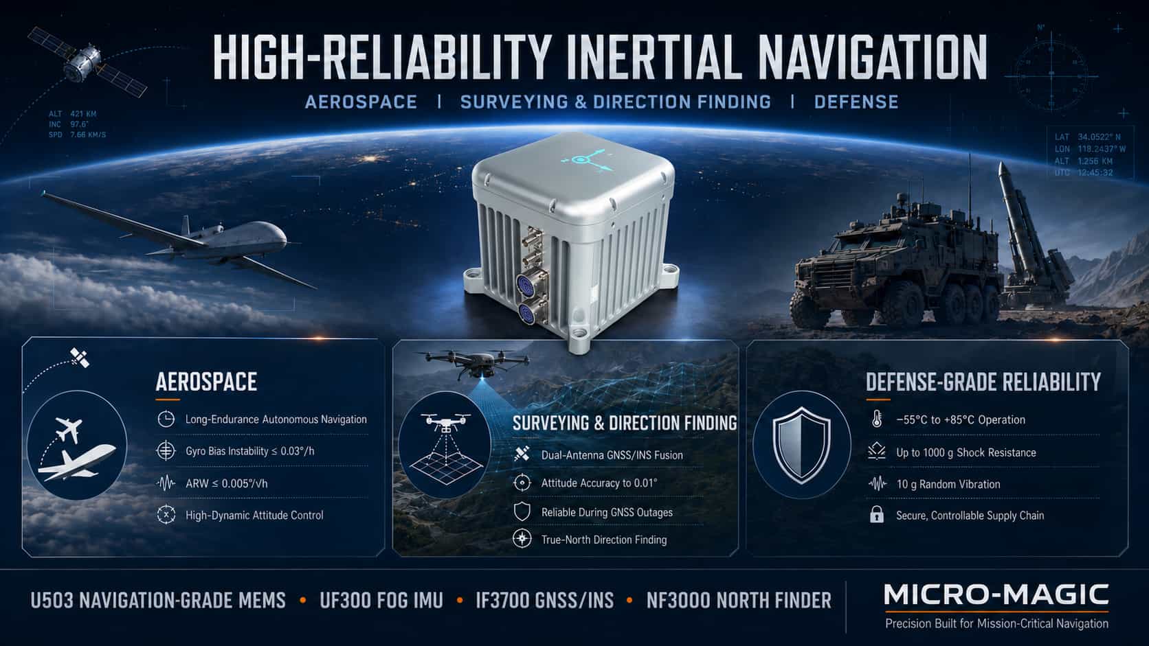
For inertial navigation systems, higher technical specifications are not necessarily better; rather, the goal is to strike an optimal balance among accuracy, size, weight, power consumption, cost, and reliability. The three major sectors—aerospace, surveying and orientation, and military equipment—have distinct technical priorities for inertial navigation products, leading to differentiated product technology roadmaps and selection criteria. The aerospace sector emphasizes high-precision attitude maintenance and long-term autonomous navigation capabilities. The surveying and orientation sector prioritizes high-precision attitude measurement and integrated navigation accuracy, with the deep fusion of inertial navigation and GNSS being critical. Military-grade applications impose the most stringent requirements regarding environmental adaptability, high-g load tolerance, and supply chain reliability. The following analysis examines the core technical specifications and typical product configurations for these three application scenarios. 1. Technical Analysis of Inertial Navigation Products in the Aerospace Sector Aerospace applications encompass a wide range of platforms, from satellites and hypersonic vehicles to tactical UAVs. Common technical requirements include high-precision attitude referencing, long-duration autonomous navigation, adaptability to high-dynamic environments, and the ability to operate across a wide temperature range. Core technical specifications center on attitude accuracy and autonomous navigation accuracy. A gyroscope bias instability of ≤0.03°/h serves as the baseline threshold for navigation-grade products, directly determining the heading drift rate; angular random walk of ≤0.005°/√h dictates short-term attitude noise levels; accelerometer bias instability of ≤10μg affects the accuracy of velocity and position dead reckoning; and scale factor stability of ≤50ppm ensures measurement linearity under high-dynamic conditions. Regarding technology roadmaps, satellite attitude control systems typically utilize fiber-optic gyro (FOG) or laser gyro IMUs (with bias instability of 0.002–0.01°/h), whereas tactical UAVs and missiles may employ high-precision MEMS IMUs (≤0.03°/h) to reduce size and cost. Taking Micro-Magic’s products as an example, the U503 series navigation-grade MEMS IMU features gyroscope bias instability of ≤0.03°/h, angular random walk of ≤0.005°/√h, and accelerometer bias instability of ≤3μg, effectively meeting the navigation requirements for lightweight UAVs and tactical missiles. The UF300 series FOG-based IMU delivers a gyro bias stability of 0.03°/h (10s smoothing) and an accelerometer bias stability of 3×10⁻⁵g (10s smoothing); a 4kHz raw data update rate ensures the capture of complete motion information during high-dynamic maneuvers. Regarding engineering implementation, a full-temperature compensation algorithm limits zero-bias variation across the entire operating temperature range to within 20% of the nominal value, while cross-axis coupling suppression of ≤0.001 rad ensures tri-axial orthogonality. Typical product configurations: Satellites and hypersonic vehicles utilize FOG-based IMUs (UF300) or laser gyro systems; large UAVs employ FOG-based IMUs (U-F3X90) or tactical-grade MEMS IMUs; tactical UAVs and missiles use navigation-grade MEMS IMUs (U503) or tactical-grade MEMS IMUs (U5000/U6300). 2. Technical Analysis of Inertial Navigation Products for Surveying, Mapping, and Orientation Applications in surveying, mapping, and orientation—such as high-precision map data acquisition, engineering surveying, marine mapping, and precision agriculture—present technical requirements that differ significantly from those in aerospace: high-precision attitude and heading directly impact the geometric accuracy of survey results; integrated navigation serves as the core operational mode, featuring deep fusion between inertial navigation and GNSS; dual-antenna assisted orientation compensates for the limited heading observability of single-antenna systems; and post-processing software can further enhance accuracy. Key performance indicators for inertial navigation systems in this sector center on integrated navigation attitude accuracy and the ability to maintain performance during short-term GNSS outages. Real-time attitude accuracy requirements are ≤0.01–0.05° for roll/pitch and ≤0.05–0.2° for heading, with post-processing capabilities improving these figures to ≤0.004–0.01° for roll/pitch and ≤0.01–0.05° for heading. Accelerometer bias stability of ≤10–30 μg ensures accuracy during short-term dead reckoning. Even after a 60-second GNSS outage, the system must maintain attitude and heading accuracy within ≤0.01°. Micro-Magic’s I3700 dual-antenna GNSS/INS integrated navigation system represents a standard configuration for surveying and orientation applications. The core technical value of the dual-antenna setup lies in its ability to determine heading: while single-antenna systems struggle to reliably measure heading when the platform is stationary or moving at low speeds, dual-antenna systems utilize carrier-phase differential technology to measure heading directly. When fused with inertial navigation data, this enables high-precision orientation across all operational conditions. North-seeking instruments are specialized devices essential for surveying and orientation; they determine true north by using a gyroscope to sense the Earth's angular rate of rotation (approximately 15°/h). Micro-Magic’s NF3000 FOG (Fiber Optic Gyro) north-seeker employs a high-precision FOG and a precision indexing mechanism. It achieves a north-finding accuracy of ≤0.1° × sec(ψ), a fully autonomous north-finding time of ≤3 minutes, and a rapid startup time of ≤30 seconds. It operates across a latitude range of -70° to +70° without relying on GNSS or being affected by geomagnetic interference. Meanwhile, the NF1000 MEMS north-seeker is designed for applications where size and power consumption are critical, while still maintaining mid-to-high-level accuracy. Typical product configurations include: FOG IMU (UF300) combined with a dual-antenna GNSS receiver and post-processing software for high-precision land or marine surveying; tactical-grade MEMS IMU (I3700 integrated navigation system) for UAV surveying; and FOG north-seekers (NF3000) or MEMS north-seekers (NF1000) for standalone north-finding and orientation tasks. 3. Technical Analysis of Military-Grade, High-Reliability Inertial Navigation Products Military-grade applications impose unique requirements on inertial navigation products that differ from commercial or industrial use cases. These include: adaptability to extreme environments (ranging from -55°C to +85°C, and from low-pressure high-altitude conditions to high-pressure deep-sea environments); tolerance for high G-loads and shocks (such as the thousands of g-forces experienced during artillery shell launches); operation in high-vibration environments (e.g., helicopter rotors or missile engines); electromagnetic compatibility and anti-interference capabilities; and supply chain security alongside autonomous control over core components. The core technical specifications for military-grade inertial navigation products center on environmental adaptability and reliability. Regarding vibration, the devices must withstand random vibration across the 10 Hz–2000 Hz range with a total RMS value of approximately 10g, as well as 100g, 11ms half-sine mechanical shocks (though actual shell launch conditions can reach several thousand g). In terms of temperature, the operating range is -55°C to +85°C, with some high-temperature, missile-borne applications requiring tolerance up to 180°C. Electromagnetic compatibility (EMC) must meet all testing requirements of the GJB 151B military standard. Regarding reliability, the Mean Time Between Failures (MTBF) is typically required to be ≥20,000 hours, with a design lifespan covering the weapon system's entire lifecycle (15–30 years). Micro-Magic’s AC-6 series quartz flexure accelerometers exemplify high-reliability, military-grade accelerometer technology. They withstand 25g vibration (20–2000 Hz) and 1000g shock (0.5ms half-sine wave)—performance levels far exceeding standard industrial products. The high-temperature AC-4 series extends the operating range to -55°C–180°C; utilizing gold-wire bonding, alumina ceramic substrates, and thick-film hybrid integrated circuit technology, these units undergo high-temperature aging (180°C for over 96 hours) and are specifically designed for environments involving aerodynamic heating, such as missiles and high-speed aircraft. Regarding the localization of core components, Micro-Magic has achieved full supply chain autonomy and control; multiple products feature a 100% domestic component rate, effectively ensuring supply chain security. Quartz flexure accelerometers and MEMS accelerometers serve distinct roles in the defense sector: the former excels in high precision and long-term stability, making it the preferred choice for strategic-grade navigation and missile guidance; the latter excels in compactness, low cost, and high integration, making it suitable for tactical-grade guidance and high-range, high-g-load fuzing applications. Typical product configurations: For long-range guided munitions and strategic missiles, FOG IMUs (UF300) or laser gyro systems paired with quartz flexure accelerometers (AC-6)—hardened for high-temperature operation—are selected. Tactical missiles and guided projectiles utilize navigation-grade MEMS IMUs (U503, high-g hardened version) or tactical-grade MEMS IMUs (U5000/U6300). Navigation systems for armored vehicles and naval vessels employ tactical-grade MEMS IMUs (U5000/U6300) with full-temperature calibration. Battlefield north-finding and orientation tasks utilize FOG north-finders (NF3000) or MEMS north-finders (NF1200), featuring 100% domestic production. 4. Summary The aerospace, surveying/orientation, and defense sectors each have distinct technical requirements for high-reliability inertial navigation products. In the aerospace sector, the core demands are high-precision attitude reference and long-duration autonomous navigation capabilities; navigation-grade products require gyro bias stability better than 0.03°/h and angular random walk better than 0.005°/√h. The surveying and orientation sector prioritizes high-precision integrated navigation and the ability to maintain accuracy during short-term GNSS outages; through deep integration of dual-antenna GNSS/INS and the use of north-finding/orientation equipment, attitude accuracy can reach the 0.01° level. Defense applications prioritize adaptability to extreme environments, resistance to high-g shock loads, and supply chain autonomy; from wide-temperature operation and tolerance to shocks exceeding 1,000g to electromagnetic compatibility and the domestic sourcing of core components, every aspect reflects the rigorous quality standards demanded of defense products. Product selection logic across these three sectors is dictated by their respective technical requirements. Understanding this logic is a fundamental prerequisite for the correct selection and application of high-reliability inertial navigation products.
Read More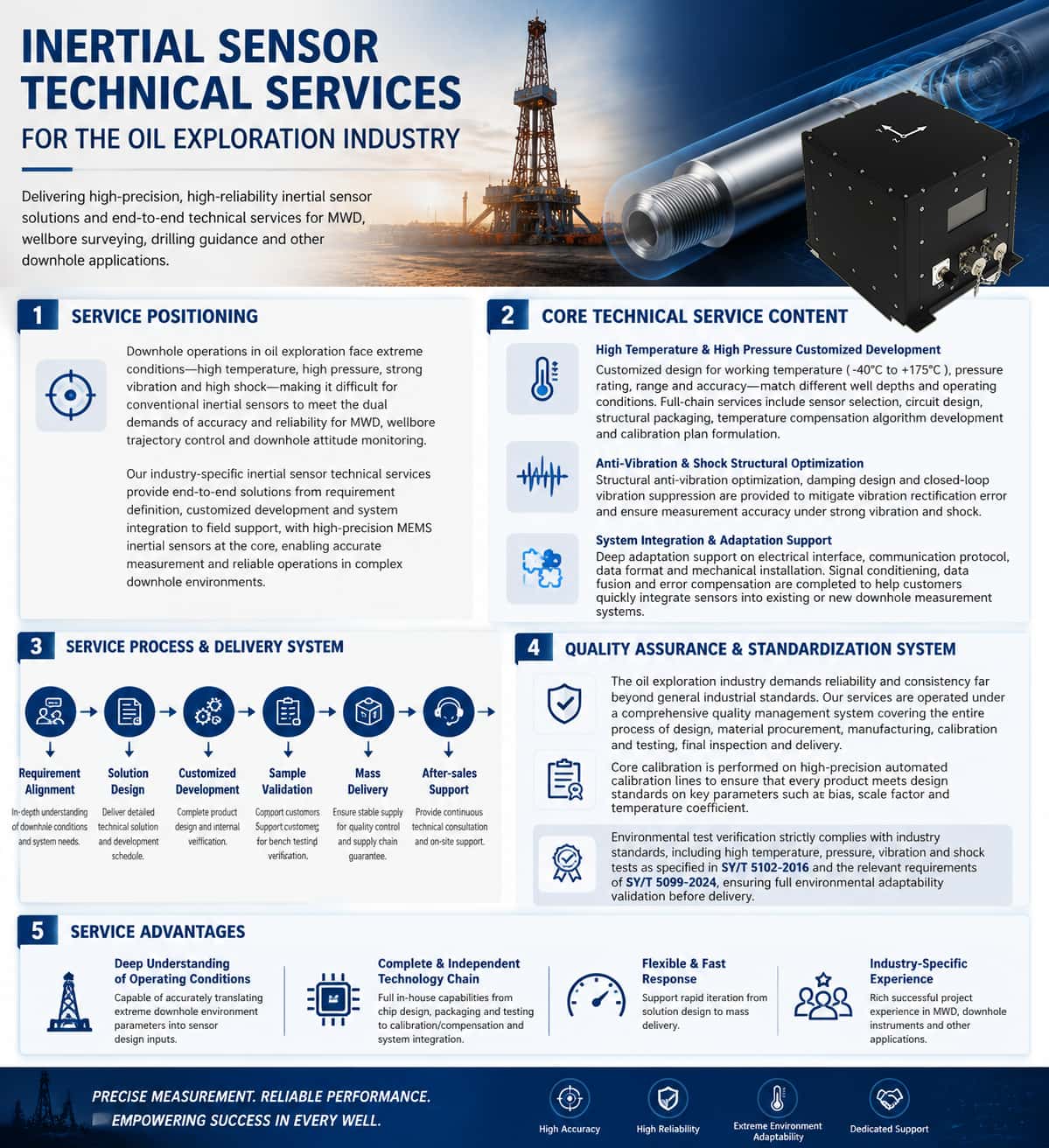
The oil and gas industry places unique and rigorous demands on inertial sensors. Whether for Measurement While Drilling (MWD), wellbore trajectory control, or downhole attitude monitoring, IMU sensors perform indispensable core measurement functions. However, downhole environments are characterized by extreme conditions—including high temperatures, high pressures, intense vibrations, and severe shocks—while varying well conditions, depths, and bottom-hole assemblies (BHAs) impose distinct requirements regarding sensor performance, dimensions, interfaces, and operating temperature ranges. Standard off-the-shelf products often fail to fully meet specific operational needs, making customized development the norm within the inertial sensor supply chain for this industry. Meanwhile, the lifecycle of oil and gas exploration equipment—from R&D to mass production—follows a typical trajectory: customized development, small-batch prototyping, and volume supply. This process reflects both the industry's uncompromising pursuit of product quality and reliability and the unique role inertial sensors play as critical components within supply chain management. These three stages are detailed below. 1. Customized Development: Application-Driven, Deeply Tailored Solutions Customized development of inertial sensors for the oil and gas industry essentially involves translating the specific downhole operational requirements of the client into engineered sensor solutions. Requirement Alignment and Solution Design. Customized development begins with a deep understanding of the client's application scenario—including well depth and temperature ranges, downhole pressure ratings, drill string vibration and shock profiles, installation space and interface constraints, measurement accuracy requirements, and communication protocols and data formats. Sensor manufacturers must be capable of rapidly responding to customization requests, particularly for specialized needs such as wide measurement ranges, vibration resistance, high-shock tolerance, and extended temperature ranges. The design phase encompasses system-level tasks—such as sensor selection, circuit design, structural design, thermal management, and vibration-resistant design—culminating in the delivery of a detailed technical proposal and development timeline. Independent Control of Core Technologies. The customized development of high-performance inertial sensors involves multiple technical stages, including structural design, ASIC circuit design, packaging and testing, and calibration and compensation. Possessing fully proprietary structural architectures and rapid customization design methodologies serves as the technical foundation for quickly meeting client-specific requirements. Meanwhile, autonomous and controllable packaging and testing lines, along with automated batch calibration assembly lines, lay the foundation for consistency, yield rates, and production capacity during the customization phase, paving the way for subsequent mass production. Design Verification and Iteration. Customized development is not a one-off delivery but a closed-loop process involving multiple rounds of design, verification, and iteration. Sensor performance, structure, and algorithms are continuously optimized based on test data and field application feedback from the customer until all operational requirements are fully met. 2. Small-Batch Prototyping: A Bridge Between Design and Physical Product Small-batch prototyping is a critical link connecting customized design with mass production; its core value lies in "verifying the highest risks at the lowest cost." Purpose and Scope of Prototyping. Small-batch prototyping typically involves producing a limited number of units (ranging from a few to several dozen) prior to formal mass production. These samples are used by customers for integration testing, downhole field verification, and system-level commissioning. The prototyping phase entails completing the full assembly, calibration, testing, and burn-in processes to ensure the samples accurately represent the performance standards of the final mass-produced units. For downhole oil and gas applications, prototypes must also undergo environmental reliability testing, such as high-temperature/high-pressure tests and vibration/shock tests. Rapid Iteration and Engineering Optimization. The small-batch prototyping phase often involves design fine-tuning and optimization—such as minor structural dimension adjustments, temperature compensation algorithm tweaks, or changes to interface definitions. The ability to respond quickly during this stage directly determines the project's overall timeline. Manufacturers with comprehensive R&D, production, and testing systems can ensure seamless, rapid transitions from conceptual design and sample testing to volume supply. Transition Management from Prototyping to Mass Production. Small-batch prototyping serves not only as technical verification but also as a trial run for production processes. Small-batch production allows for the early identification of potential bottlenecks in manufacturing, testing, and the supply chain, ensuring thorough preparation for subsequent volume supply. 3. Volume Supply: Quality Systems and Supply Chain Assurance Volume supply represents the final delivery stage of customized development and serves as the ultimate test of an inertial sensor supplier's comprehensive capabilities within the oil and gas industry. Quality Management System. The oil and gas industry imposes quality management system requirements on suppliers that far exceed those of general industrial sectors. API Q1 is a quality management system standard specific to the oil and gas industry, introduced by the American Petroleum Institute (API); it is more rigorous than ISO 9001. The API Q1 specification covers the entire process—from design and production to the supply chain—requiring organizations to demonstrate their ability to consistently provide reliable products. For inertial sensor manufacturers, establishing and operating an API Q1 quality management system represents a pivotal leap from merely being "capable of manufacturing" to "delivering reliable performance." Supply Chain Management. During the mass supply phase, sensor manufacturers must establish stable raw material supply channels, controllable outsourced processing resources, and efficient logistics and delivery systems. Ancillary materials—such as specific inertial sensors, chassis, housings, PCBs, and various electronic components—are often procured externally, necessitating strict supplier qualification audits and quality control. Core processes—including high/low-temperature sensor calibration, error compensation, performance testing, and assembly/debugging—are performed independently by the manufacturer, leveraging their own technical strengths. Batch Calibration and Consistency Control. The accuracy of inertial sensors depends not only on the chip itself but, more importantly, on the precision of calibration and compensation. During mass supply, manufacturers require fully in-house developed automated batch calibration lines. By combining proprietary equipment structures and fixtures with optimized calibration algorithms and communication architectures, they can ensure that every product meets performance standards while achieving high-volume output. The consistency and repeatability of mass-produced products regarding key metrics—such as bias, scale factor, and temperature coefficients—serve as critical benchmarks for evaluating mass supply capabilities. Summary The lifecycle of inertial sensors for the oil and gas industry—spanning custom development, small-batch prototyping, and mass supply—forms a complete value chain connecting market demands to finished products. Custom development translates downhole operating conditions into product specifications; small-batch prototyping mitigates technical risks through physical verification; and mass supply relies on quality management systems and supply chain capabilities to ensure reliable delivery. For manufacturers, possessing both robust technical expertise and comprehensive service capabilities is essential; these factors constitute the industry's entry threshold and core competitiveness.
Read More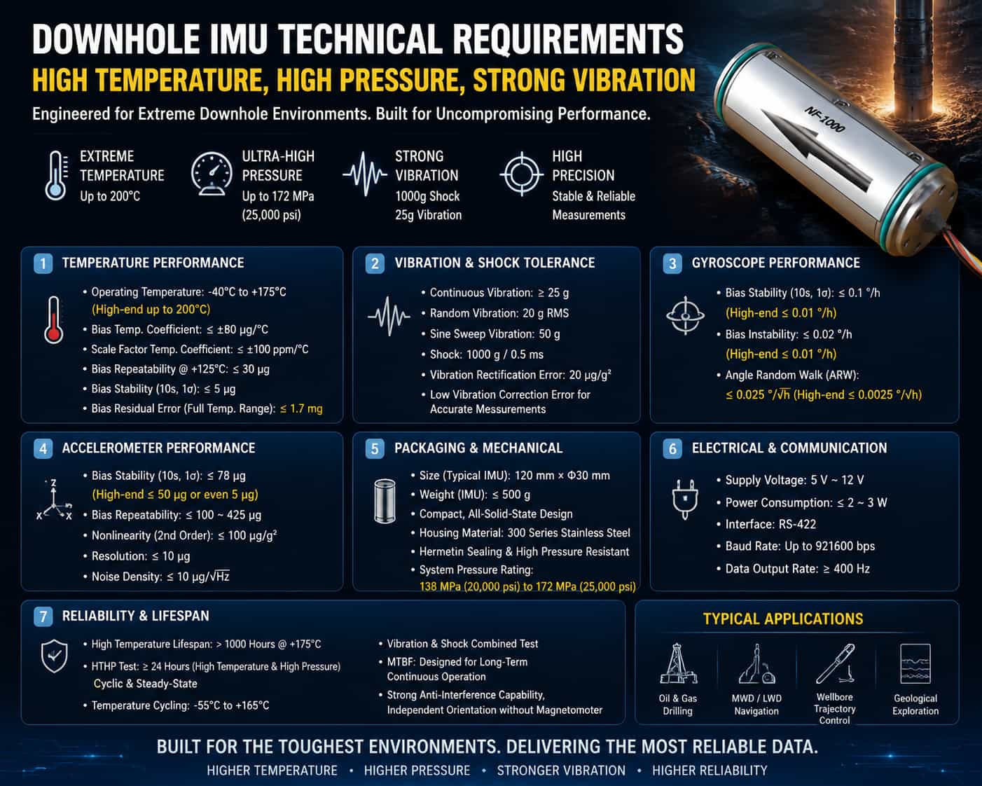
I. Introduction In downhole operations such as oil drilling and geological exploration, Inertial Measurement Units (IMUs) perform core functions including wellbore trajectory control, Measurement While Drilling (MWD), attitude determination, and navigation/positioning. However, the downhole environment is a "purgatory" for sensors: temperatures can exceed 150°C or even 200°C, pressures surpass 100 MPa, and the drill string is subjected to continuous, intense vibration and high-impact loads. In such environments, conventional IMU sensors are highly susceptible to accuracy drift, reduced service life, and even total failure. Therefore, defining the rigorous technical specifications for IMU sensors operating in high-temperature, high-pressure, and high-vibration downhole environments is crucial for ensuring the safety and accuracy of drilling operations. The technical specifications for downhole IMU sensors can be categorized into six key dimensions: temperature adaptability, vibration and shock tolerance, accuracy and stability, packaging and dimensional constraints, electrical and power characteristics, and operational life and reliability. These are detailed below. II. Temperature Adaptability Specifications Temperature represents the most severe challenge posed by the downhole environment to IMU sensors. The global geothermal gradient is generally 25°C per kilometer of depth; in ultra-deep wells, bottom-hole temperatures often exceed 150°C. Consequently, the operating temperature range is a primary technical specification. Operating Temperature Range: Downhole IMU sensors typically require an operating temperature range of -40°C to +125°C, while high-end products must withstand -40°C to +175°C or higher. Some sensors designed for ultra-deep wells can already tolerate extreme temperatures of 180°C to 200°C. The lower limit of the operating temperature range cannot be overlooked either, as equipment must withstand low temperatures during operations in cold regions or winter conditions. Full-Temperature-Range Compensation and Temperature Stability: Merely having the capability to operate across a wide temperature range is insufficient to meet accuracy requirements. Sensors must undergo precision compensation across the entire temperature range to ensure low drift and high repeatability despite extreme temperature fluctuations. Key specifications include: the bias temperature coefficient typically needs to be controlled within ±80 μg/°C, and the scale factor temperature coefficient within ±100 ppm/°C. In a high-temperature environment of +125°C, the accelerometer's bias repeatability must be controlled within 30 μg, and its bias stability (10-second 1σ) must be less than 5 μg. Residual bias error across the temperature range is a key parameter for assessing temperature adaptability; high-end products can keep this within 1.7 mg. III. Vibration and Shock Tolerance Specifications During rotary drilling, the downhole drill string is subjected to continuous wide-band random vibration and instantaneous, intense shocks caused by the drill bit breaking rock. This represents the second major challenge for IMU sensors. Continuous vibration tolerance: Sensors must withstand continuous vibration environments, typically requiring tolerance for continuous vibration exceeding 25g (gravitational acceleration). Under random vibration conditions, some high-performance sensors have successfully undergone combined testing involving 20g RMS random vibration and 50g sinusoidal swept-sine vibration. Instantaneous shock tolerance: Drill bit impacts generate extremely high peak instantaneous accelerations; sensors must withstand high-intensity shocks in the range of 1000g/0.5ms. This specification directly determines the sensor's survivability under harsh operating conditions. Vibration suppression capability: Beyond merely "withstanding" vibration, sensors must also "suppress" the impact of vibration on measurement accuracy. Vibration rectification error is a critical factor; advanced closed-loop architectures can reduce this error tenfold, achieving a vibration suppression capability of 20 μg/g². Low vibration rectification error ensures that true gravity and angular velocity signals can be clearly extracted amidst the complex vibrations of the drill string. IV. Accuracy and Stability Specifications While meeting environmental adaptability requirements, IMU sensors must also possess sufficient measurement accuracy; otherwise, attitude determination and trajectory control would be meaningless. Gyroscope specifications: Gyro bias stability is a core parameter for measuring gyroscope accuracy. Requirements are typically below 0.1°/h (10-second 1σ), with high-end products achieving 0.01°/h or even lower. Bias instability requirements are below 0.02°/h, with some products achieving levels within 0.01°/h. Angle Random Walk (ARW) is a critical metric for gyro noise levels; requirements start as low as 0.025°/√h, with high-end products achieving 0.0025°/√h. Accelerometer specifications: Bias stability requirements are typically below 78 μg, with high-performance products achieving less than 50 μg or even 5 μg (10-second, 1σ). Bias repeatability must be controlled within the 100 μg to 425 μg range. The second-order nonlinearity coefficient must be less than 100 μg/g² to ensure linearity in acceleration measurements across a wide dynamic range. Regarding resolution, high-performance accelerometers can achieve levels below 10 μg. Noise density, a key indicator of the accelerometer's noise floor, is typically required to be below 10 μg/√Hz. Long-term stability: Given that downhole operations can span weeks or even months, the long-term stability of sensor bias and scale factor is crucial. The combined monthly repeatability for bias must be controlled within 150 μg, and for scale factor, within 150 ppm. The combined monthly repeatability for the nonlinearity coefficient must be controlled within ±40 μg/g². V. Packaging and Dimensional Constraints Downhole space is extremely limited; IMU sensors must meet strict miniaturization and packaging requirements. Physical dimensions: Sensors require a compact design to fit into downhole tools with limited diameters. A typical high-performance IMU measures approximately 120 mm × Φ30 mm. Discrete components, such as accelerometers, require even greater miniaturization, with typical dimensions as small as Φ18.2 × 16 mm. Weight: Lightweight design is a standard requirement for downhole instruments. The weight of a complete IMU is typically kept under 500 g, while discrete accelerometers can weigh as little as 25 g. Structural design: An all-solid-state design with no moving parts is the preferred choice for downhole IMUs, significantly enhancing reliability in environments subject to intense vibration and high shock. An integrated cylindrical design facilitates embedding into downhole tools without altering existing equipment layouts. The housing must be constructed from corrosion-resistant, high-strength materials, such as 300-series stainless steel. Sealing and Pressure Resistance: As a core component of downhole instruments, the IMU sensor requires packaging that meets high-pressure sealing standards. Although the IMU is typically housed within a pressure-resistant tool string, its packaging design must still ensure airtight integrity and insulation performance in high-temperature, high-pressure environments. System-level pressure resistance specifications typically require ratings of 138 MPa (20,000 psi) or even 172 MPa (25,000 psi). VI. Electrical and Power Consumption Specifications Downhole power supply conditions are limited; therefore, the electrical characteristics of the IMU sensor directly impact system feasibility and operational duration. Supply Voltage: Must support a wide input voltage range to accommodate unstable downhole power conditions; typical requirements range from 5V to 12V. Power Consumption: Low power consumption is a critical requirement. The power consumption of the complete IMU unit generally needs to be kept within 2W to 3W. Low power consumption not only alleviates the load on the downhole power supply system but also minimizes the sensor's own temperature rise, facilitating thermal management in high-temperature environments. Communication Interface: Must be equipped with a bus interface suitable for long-distance downhole transmission; RS-422 is a common choice. The communication baud rate must meet real-time requirements, typically reaching up to 921,600 bps. The data refresh rate must satisfy the control system's real-time needs, with a typical value of no less than 400 Hz. VII. Operational Life and Reliability Specifications Downhole operations cannot be arbitrarily interrupted; therefore, the IMU sensor must possess sufficient operational life and reliability. High-Temperature Operational Life: The sensor must be capable of continuous operation for several thousand hours at its rated operating temperature. At the extreme operating temperature of +175°C, a service life exceeding 1,000 hours is required. Reliability Testing: The sensor must pass a series of environmental reliability tests, including High-Temperature High-Pressure (HTHP) cycling and steady-state tests (typically ≥24 hours), temperature cycling tests (e.g., -55°C to +165°C), and combined high-temperature vibration tests. Mean Time Between Failures (MTBF) serves as a quantitative measure of reliability and must meet the requirements for continuous downhole operation. Anti-interference capability: In downhole environments characterized by strong magnetic interference, the IMU must possess the ability to orient itself autonomously—independent of the Earth's magnetic field—thereby overcoming the failure issues faced by traditional magnetic compasses in ferromagnetic environments (such as inside steel casings). Conclusion The technical specifications for downhole IMUs—designed to withstand high temperatures, high pressures, and intense vibrations—encompass six key dimensions: temperature adaptability, tolerance to vibration and shock, measurement accuracy and stability, package size, electrical power consumption, and operational lifespan/reliability. These parameters are interconnected and mutually constraining. Industry trends indicate a continuous rise in upper operating temperature limits—moving from 125°C toward 150°C, 175°C, and even 200°C—alongside ongoing improvements in vibration suppression and measurement accuracy, as well as optimized miniaturization and low-power designs. These technological advancements are driving the evolution of downhole IMU sensors toward higher temperature and vibration tolerance, greater accuracy, and extended service lives, thereby providing increasingly robust technical support for the exploration and development of deep-earth oil and gas resources.
Read More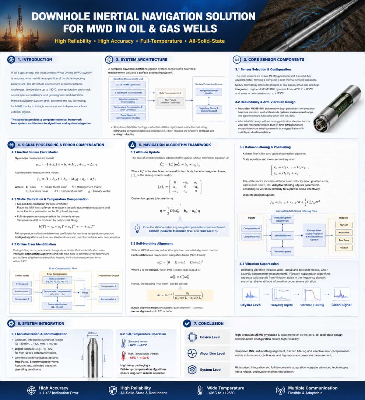
Introduction In oil and gas drilling engineering, Measurement While Drilling (MWD) systems perform the critical task of acquiring real-time borehole trajectory parameters. The downhole environment imposes extremely rigorous demands on navigation systems—including temperatures exceeding 150°C, continuous intense vibration and shock, severe spatial constraints, and significant geomagnetic field distortion—all of which create technical barriers for downhole navigation. Inertial Navigation Systems (INS) have emerged as a key technical approach for MWD due to their high level of autonomy and independence from external signals. This paper provides a technical analysis covering five aspects: system architecture, core components, error compensation, navigation algorithms, and system integration. System Architecture A complete inertial MWD system consists of a downhole measurement unit and a surface processing system. The downhole unit is installed within a drill collar near the drill bit and integrates an Inertial Measurement Unit (IMU)—comprising tri-axial gyroscopes and tri-axial accelerometers—along with signal acquisition circuitry, a power module, and communication interfaces. The surface system is responsible for data reception, navigation computation, borehole trajectory visualization, and decision support. Current mainstream solutions employ strapdown inertial measurement technology, in which the IMU is rigidly mounted inside the drilling tool. By eliminating complex mechanical stabilization structures, this approach fundamentally enables system miniaturization and enhances reliability. Core Sensor Components Sensor Selection and Configuration The core sensors of the LWD (Logging While Drilling) inertial navigation system consist of a tri-axial MEMS gyroscope and a tri-axial MEMS accelerometer, providing comprehensive six-degree-of-freedom inertial sensing capabilities. MEMS technology has become the mainstream choice due to advantages such as low power consumption, compact size, and high integration potential. High-end MEMS IMUs operate within a temperature range of -40°C to +125°C, with some accelerometers capable of withstanding temperatures up to +175°C. Redundant Configuration and Vibration-Resistant Design Redundant MEMS-IMU configuration is a key method for enhancing reliability. A typical dual-inertial-navigation architecture incorporates both high-precision and low-precision IMUs, balancing accuracy and cost while extending the dynamic measurement range. The system remains functional even if one sensor unit fails. Regarding vibration resistance, the fully solid-state design contains no moving mechanical parts, fundamentally eliminating mechanical wear and resonance-induced fatigue. An internal platform structure encases the core sensing elements within a robust mount, utilizing a multi-layer design to absorb and dampen vibration energy. Signal Processing and Error Compensation Inertial Sensor Error Models Measurements from MEMS inertial sensors contain various error components. The gyroscope measurement model is: ω̃ = ω + b_g + s_g∙ω + M_g∙ω + n_g + ε_g(T) The accelerometer measurement model is: ã = a + b_a + s_a∙a + M_a∙a + n_a + ε_a(T) + g Where: "b" = bias; "s" = scale factor error; "M" = installation error matrix; "n" = random noise; "ε(T)" = temperature drift; "g" = gravitational acceleration vector. Achieving high-precision measurement requires the calibration and compensation of each error term. Static Calibration and Temperature Compensation Static error compensation is performed during the factory calibration phase. Taking the six-position calibration of an accelerometer as an example, observation equations—$y = H \cdot X + v$—are established by placing the IMU in six different orientations. The error parameter vector $X$ is then solved using the least-squares method. Full-temperature-range compensation is critical for dynamic compensation. Polynomial fitting models are commonly used to characterize temperature drift: $\varepsilon(T) = k_0 + k_1 T + k_2 T^2 + \dots + k_n T^n$ Fitting coefficients ($k_0, k_1, \dots, k_n$) are determined through full-temperature-range calibration experiments to enable real-time temperature correction. In recent years, intelligent algorithms—such as neural networks—have also been introduced to efficiently compensate for nonlinear errors. Online Error Identification Error parameters change dynamically during the drilling process, a scenario that traditional offline calibration struggles to address. Online error identification utilizes intelligent optimization algorithms and real-time data to dynamically identify error parameters and achieve adaptive compensation, thereby keeping the borehole inclination measurement error within 1.43°. The complete error compensation process is as follows: 5. Navigation Algorithm Framework 5.1. Attitude Update The core of strapdown inertial navigation computation is the update of the attitude matrix; its differential equation is: Let be the attitude transformation matrix from the carrier frame to the navigation frame.The skew-symmetric matrix of the vector: The discretization solution employs a quaternion update algorithm, and the quaternion differential equation is: Three key navigation parameters—azimuth, inclination, and tool face angle—can be extracted from the attitude matrix. 5.2. Self-North-Seeking Initial Alignment In the absence of GPS signals downhole, self-north-seeking serves as the core technology for initial alignment. The projection of the Earth's angular velocity of rotation onto the navigation frame (North-East-Up coordinate system) is: ,corresponds to the local latitude. When the IMU is stationary, the gyro output is: From this, the heading angle (relative to true north) is calculated: The system offers multiple alignment modes: rapid alignment with an accuracy of approximately 1°, and precision alignment achieving 0.5° or better. 5.3. Kalman Filtering and Positioning Kalman filtering is the core optimal estimation algorithm for the inertial navigation system; the state and observation equations are as follows: The state vector comprises attitude errors , velocity errors, position errors, and sensor errors. To address the downhole vibration environment, adaptive filtering is employed; parameters are dynamically adjusted based on vibration intensity to effectively suppress noise. The discrete position recursion formula is:
Read More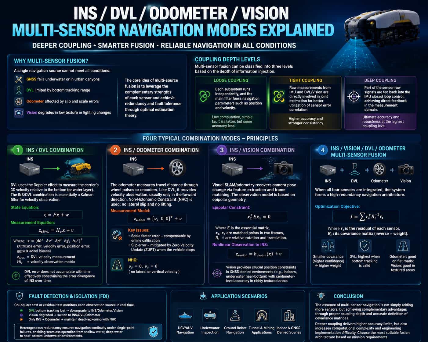
A single navigation source struggles to meet the requirements for full operational coverage: GNSS fails underwater or in urban canyons; DVL is limited by bottom-tracking range; odometry suffers from wheel slip and scale factor errors; and vision-based systems degrade in low-texture environments or under varying lighting conditions. The core concept of multi-source fusion lies in leveraging the complementary characteristics of various sensors to achieve redundancy and fault tolerance through optimal estimation theory. This paper systematically analyzes four typical integrated navigation modes based on two dimensions: coupling depth and information complementarity. **Classification of Coupling Depth** Multi-source fusion can be categorized into three levels based on the depth of information integration: * **Loose coupling** represents the lowest level of coupling, where subsystems perform independent calculations, and a master filter fuses navigation parameters such as position and velocity. Its advantages include low computational load and simple fault isolation; however, accuracy loss arises primarily from the independent nature of the subsystem calculations. * **Tight coupling** elevates observation to the level of raw measurements; raw data from the IMU and DVL (or vision sensors) are directly involved in a joint estimation process, utilizing the temporal correlation of sensor error characteristics to achieve superior estimation. * **Deep coupling** goes a step further by incorporating raw signals from certain sensors into the IMU's closed-loop control, establishing direct feedback in the measurement domain; this represents the highest level of coupling, enabling ultimate precision and maximum robustness. **Principles of Four Integrated Navigation Modes** (1) **INS/DVL Integration** The DVL measures the vehicle's 3D velocity relative to the seabed (or water layer) using the Doppler effect. INS/DVL integration is essentially a Kalman filtering process based on velocity observations: DVL velocity measurements serve as external observations to correct INS velocity errors, thereby suppressing position drift. The state equations and observation equations can be expressed as follows: Here, the state vector $x$ includes attitude, velocity, and position errors, as well as gyro and accelerometer biases, while $H$ is the velocity observation matrix. DVL errors do not accumulate over time, effectively constraining the error growth of the inertial navigation system. INS/Odometer Integration The odometer measures travel distance via wheel pulses or encoders; like the DVL, it falls under the category of velocity observation. However, its constraint is typically limited to forward velocity, necessitating the use of non-holonomic constraints (NHC)—which assume the vehicle neither sideslips nor bounces (i.e., lateral and vertical velocities are zero). Its observation model can be expressed as: Key issues associated with odometry include scale factor errors and wheel-slip errors; the former can be compensated for through online calibration, while the latter requires velocity resetting at standstill intervals using Zero-Velocity Update (ZUPT) techniques. (3) INS/Vision Integration Visual SLAM/odometry recovers changes in camera pose through feature point extraction and inter-frame matching, with an observation model that can be described by epipolar geometry constraints: Here, E = t∧R is the essential matrix, where R and t represent the relative rotation and translation between two frames, forming a nonlinear observation of the inertial navigation system's attitude and position: Vision provides critical positional constraints in GNSS-denied environments (such as indoors or near the seabed), achieving centimeter-level accuracy in texture-rich areas. Tightly coupled visual-inertial systems typically employ sliding-window optimization (e.g., MSCKF) to jointly optimize visual reprojection errors and IMU pre-integration factors, yielding an order-of-magnitude improvement in accuracy compared to loosely coupled systems. (4) Multi-source fusion of INS, vision, DVL, and odometry When all four sensors are integrated, the system establishes a highly redundant navigation architecture. The objective function for optimization is the weighted sum of the residuals from each sensor: The covariance matrix Σ is central to determining fusion weights: the smaller the covariance (indicating lower uncertainty), the higher the weight assigned to the sensor. The DVL carries the highest weight when bottom-tracking is valid; odometry ranks second on smooth terrain; and vision provides lateral constraints in areas rich in visual texture. A Fault Detection and Isolation (FDI) mechanism monitors observation sources in real-time for anomalies using Chi-square or residual tests. If DVL bottom-tracking fails, the system automatically degrades to an INS/odometry/vision fusion mode; if vision degrades, it switches to INS/DVL/odometry; if only INS and odometry remain, it reverts to a pure INS mode constrained by Non-Holonomic Constraints (NHC). A heterogeneous redundant design ensures navigation continuity despite single-point failures, enabling seamless coverage across diverse operational scenarios—from shallow and deep water to near-bottom underwater environments. Conclusion Multi-sensor integrated navigation is not merely about increasing the number of sensors; rather, it relies on the judicious selection of coupling depth and the precise definition of covariance matrices to achieve complementary sensor performance. While deeper coupling offers higher potential accuracy, it also increases computational complexity and engineering implementation challenges; therefore, the optimal fusion architecture should be selected based on specific mission requirements.
Read More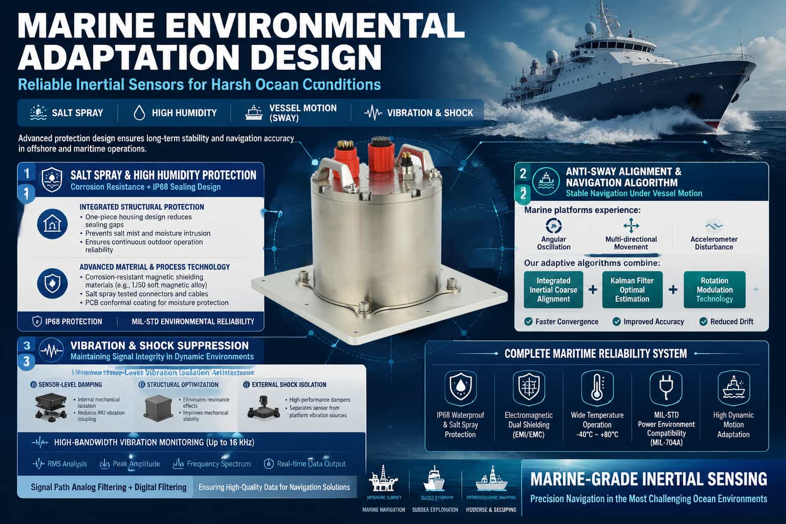
The marine environment poses severe challenges to inertial navigation systems (INS): salt spray corrosion, high humidity condensation, continuous swaying motion, and multi-dimensional vibration all directly affect the system's accuracy and reliability. If the INS cannot effectively cope with these environmental stresses, alignment failures, accuracy degradation, and even hardware damage will occur. Therefore, adaptive design is the core technological barrier that distinguishes marine-grade INS from general-purpose products. Salt Spray and High Humidity Environment Protection Design Chloride ions in salt spray are highly corrosive to metal structural components and electrical connections, while high humidity environments can lead to decreased insulation performance and signal crosstalk. Effective protection strategies should be developed from two aspects: structural sealing and material selection. Integrated structural design reduces assembly gaps and the number of connectors. A one-piece molded shell can fundamentally block the salt spray intrusion path, and combined with positioning grooves and sealing gasket structures, ensures continuous protection during long-term outdoor operations. Regarding material and process selection, the fiber optic ring frame and cover should use magnetic shielding materials (such as 1J50 soft magnetic alloy) to achieve magnetic protection while also ensuring corrosion resistance. Connectors and cables must meet salt spray testing standards, and circuit boards must undergo a three-proof coating process. IP68 protection, conforming to MIL-STD standards, is currently the industry's effective solution for high-humidity salt spray environments. Alignment and Navigation Algorithms under Swaying Conditions Under swaying conditions, the initial alignment of the inertial navigation system (INS) faces two major disturbances: angular sway (periodic attitude changes) and linear vibration (accelerometer output fluctuations). Traditional static base alignment algorithms struggle to converge under these conditions. Anti-sway alignment methods employ an integral inertial frame coarse alignment strategy, utilizing attitude updates to eliminate the influence of angular sway and weakening linear vibration interference through force integration. Based on this, feedback-corrected Kalman filtering is used for fine alignment optimal estimation. Experiments show that this method significantly improves both horizontal and vertical heading accuracy under swaying conditions compared to traditional rotation modulation schemes. Rotation modulation technology is another effective means of suppressing gyro scaling factor errors. By periodically rotating the IMU, constant drift is modulated into a periodically changing signal, which cancels each other out during integration, thereby reducing the long-term impact of swaying on heading accuracy. Vibration Suppression and Shock Resistance Design Vibration affects inertial navigation system (INS) accuracy through two mechanisms: first, mechanical resonance causes IMU output distortion; second, high-frequency vibration couples into the gyroscope and accelerometer measurement channels, forming spurious signals. A three-stage vibration reduction architecture is the current mainstream design approach: the first stage achieves internal damping isolation at the IMU sensor level; the second stage eliminates resonant frequencies through shell structure optimization; and the third stage uses external dampers to physically separate the equipment from the carrier structure. Some high-end systems also integrate high-bandwidth (up to 16kHz) vibration monitoring tools, outputting RMS, peak amplitude, and frequency for each frequency band in real time, providing data support for structural optimization. Analog filtering in the signal pipeline can pre-attenuate vibration noise at the front-end hardware level, and, in conjunction with digital filtering algorithms, ensures the signal quality entering the calculation stage. Comprehensive Protection System In addition to the above-mentioned specialized designs, mature maritime INS systems also need to consider: power environment adaptability (meeting MIL-704A standards), electromagnetic double-layer shielding (to cope with interference from shipboard radar and communication equipment), and wide temperature range operation capability (-40℃~80℃). These measures together constitute a complete design system for adaptability to harsh environments, which is the fundamental guarantee for the inertial navigation system to maintain mapping-level accuracy under marine conditions.
Read More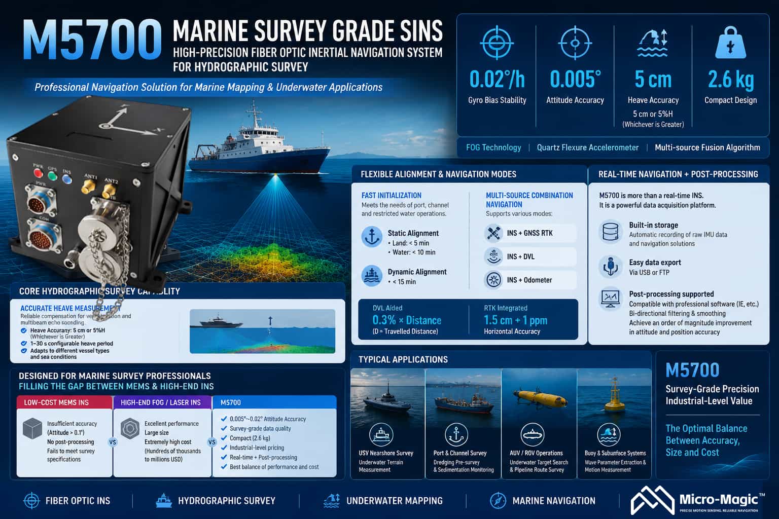
The M5700 Fiber-Optic Inertial Navigation System is a high-precision strapdown inertial navigation system designed for marine surveying and high-end navigation applications. It integrates fiber-optic gyroscopes, quartz flexure accelerometers, and multi-source fusion navigation algorithms. With a gyroscope bias stability of 0.02°/h and an attitude accuracy of 0.005°, the system establishes a strong technical position in the field of maritime surveying. **Core Surveying Capabilities** Heave measurement is a critical requirement in marine surveying. The M5700 offers a heave accuracy of 5 cm or 5% of heave height (whichever is greater), effectively compensating for the impact of vessel motion on multibeam bathymetric data. The system supports configurable heave periods ranging from 1 to 30 seconds, adapting to various sea conditions and vessel characteristics. Alignment solutions are flexibly adapted to operational scenarios: static base alignment takes less than 5 minutes (on land) and less than 10 minutes (in water), while dynamic base alignment takes less than 15 minutes, meeting the need for rapid operations in restricted waters such as ports and channels. Multi-source integrated navigation supports various modes, including Inertial/GNSS, Inertial/DVL, and Inertial/Odometer. With DVL assistance, position accuracy reaches 0.3% of distance traveled (D); when integrated with GNSS RTK, horizontal accuracy reaches 1.5 cm + 1 ppm, ensuring navigation continuity during GNSS signal outages. **Post-processing Capabilities** Post-processing capability is a key differentiator that sets the M5700 apart from purely real-time navigation products. The system features built-in storage, automatically recording raw IMU data and navigation solutions upon power-up, which users can easily export via USB or FTP. The stored IMU data can be directly imported into professional post-processing software (such as IE) for bidirectional filtering and smoothing, yielding attitude and position accuracy an order of magnitude better than real-time solutions. This capability allows the M5700 to serve not only real-time operations but also as a data acquisition front-end, providing the raw data foundation for refined processing and meeting the rigorous accuracy requirements of applications such as hydrographic surveying and underwater terrain modeling. Market Positioning The M5700 is precisely positioned for the mid-range marine surveying and mapping market. Its core clientele includes hydrographic bureaus, maritime safety administrations, waterway authorities, marine geological survey agencies, and manufacturers of unmanned surface vessels (USVs) and ROVs. The current market is sharply polarized: low-end MEMS products lack sufficient accuracy (attitude >0.1°) and lack post-processing capabilities, failing to meet surveying standards; conversely, high-end fiber-optic or laser-based inertial navigation systems offer superior performance but are bulky and prohibitively expensive (ranging from hundreds of thousands to over a million RMB), exceeding the budgets of most commercial projects. Built around fiber-optic gyroscope technology, the M5700 delivers genuine survey-grade data with attitude accuracy in the 0.005°–0.02° range. It combines a compact 2.6 kg design and industrial-grade pricing with dual-mode output (real-time navigation and post-processing), effectively filling this market gap. Typical applications include nearshore underwater topographic surveying using small-to-medium USVs; pre-dredging sweeps and siltation monitoring in port channels using manned vessels; underwater target searches and pipeline route surveys using AUVs/ROVs; and wave parameter extraction for buoy and subsurface mooring systems. The M5700 enables professional users to obtain attitude and heave data that strictly comply with surveying standards within a limited budget, making it the optimal solution for balancing performance and cost in marine surveying projects.
Read More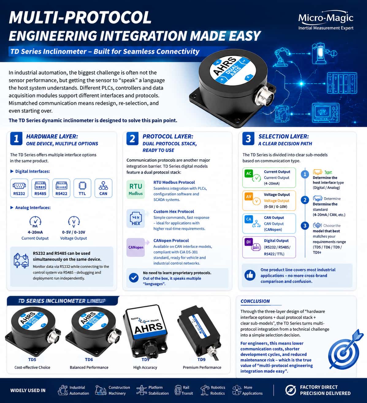
In the era of rapid development in industrial automation and the Internet of Things (IoT), the "communication capability" between sensors and control systems often determines the complexity of project implementation and overall system reliability. With their extensive communication interface configurations, the TD series of dynamic inclinometers offers flexible, comprehensive solutions for attitude measurement needs across diverse scenarios. 1. Overview of Communication Interfaces: Flexible Selection and Adaptation The TD series encompasses a wide range of models covering all mainstream communication methods used in the industrial sector, broadly categorized into digital and analog interfaces. Digital interfaces include RS232, RS485, RS422, TTL, and CAN bus; analog interfaces are available in both current and voltage types, supporting outputs such as 4–20mA and 0–20mA (current) and 0–5V, 0.5–4.5V, and 0–10V (voltage). Regarding communication protocols, the products are compatible with Modbus RTU, the custom 0x68 protocol, and CANopen, truly achieving "multi-purpose functionality and on-demand adaptation." 2. Digital Interfaces: Flexible Data Exchange Channels TD series models with digital interfaces support various output methods, including RS232, RS485, RS422, TTL, and CAN. This "multi-interface" design philosophy allows engineers to select the communication method best suited to their specific requirements: RS232 is ideal for short-range, point-to-point communication, offering ease of debugging and strong compatibility. RS485 supports long-distance transmission of up to 2,000 meters and allows for multiple sensor nodes, making it the preferred choice for industrial fieldbuses. RS422 supports full-duplex communication, making it suitable for scenarios requiring simultaneous data transmission and reception. TTL operates at 3.3V/5V logic levels, facilitating direct integration with embedded systems (such as STM32 and Arduino). CAN bus is designed specifically for automotive and industrial control applications, offering robust interference resistance and high real-time performance. 3. Analog Interfaces: Classic, Reliable Industrial Signals For traditional industrial environments that still rely heavily on PLC analog data acquisition modules, the TD series provides a comprehensive range of analog output solutions. Current-output models support 4–20mA, 0–20mA, and 0–24mA ranges. The 4–20mA range is the most common industrial standard, offering advantages such as strong noise immunity and suitability for long-distance transmission. Zero-point output corresponds to 12mA (for the 4–20mA mode) or 10mA (for the 0–20mA mode), with angle calculation based on a simple, reliable linear proportional relationship. Voltage-output models support three output ranges—0–5V, 0.5–4.5V, and 0–10V—ensuring compatibility with the analog input modules of various PLCs. Zero-point output corresponds to 2.5V (for the 0–5V mode) or 5V (for the 0–10V mode), utilizing a similarly straightforward calculation method. The primary advantage of analog interfaces is their "plug-and-play" capability; there is no need to write complex communication protocols. Angle values can be derived directly by acquiring voltage or current readings via an ADC, significantly lowering the barrier to system integration. 4. Communication Protocols: A Blend of Standardization and Customization At the protocol level, the TD series balances standardization with flexibility. The Modbus RTU protocol, a de facto standard in industrial automation, is widely supported via the RS485 interface. By using standard Modbus function codes (such as 0x03 for data reading), the device can easily interface with various PLCs, HMI/SCADA software, and control systems. The custom protocol is a highly efficient hexadecimal communication protocol used by digital models. Data frames begin with the identifier 0x68 and include fields for data length, address code, command word, data payload, and checksum. This protocol supports a comprehensive range of functions—including reading single-axis or dual-axis angles, setting relative/absolute zero points, adjusting baud rates, toggling between request-response and automatic output modes, and modifying module addresses—all characterized by concise commands and rapid response times. The CANopen protocol is specifically designed for products with CAN interfaces and utilizes the standard CANopen protocol stack. Parameter configuration is handled via SDOs (Service Data Objects), while real-time angle data transmission occurs via PDOs (Process Data Objects). It supports features such as node ID configuration (default 0x05), baud rate settings (configurable from 100kbps to 1Mbps), and multiple data output rates (5Hz to 50Hz), fully meeting the requirements of industrial control and automotive applications. 5. Selection Recommendations When selecting a model for a specific project, consider the following factors: Control System Interface: If the system already utilizes an RS485 bus, prioritize RS485+Modbus; if using PLC analog modules, opt for 4–20 mA current output or 0–10 V voltage output. Transmission Distance: For long distances (>50 meters), RS485 or 4–20 mA current output is recommended; for short distances, RS232, TTL, or voltage output are suitable options. Real-time Requirements: For high-real-time applications (such as robotics or vehicle control), a CAN interface is recommended; for general industrial monitoring, either digital or analog interfaces will suffice. Multi-node Networking: When multiple sensors need to be connected in parallel, RS485+Modbus or CAN bus is the optimal choice. Conclusion By featuring a dual-interface design (supporting both digital and analog outputs) and compatibility with multiple protocols—including Modbus, custom protocols, and CANopen—the TD series dynamic inclinometers truly embody the design philosophy of "one platform, multiple interfaces, and on-demand adaptation." Whether you are building a new Industrial IoT system or upgrading a traditional PLC control cabinet, the TD series offers the ideal communication solution, making inclinometer data acquisition simpler than ever.
Read More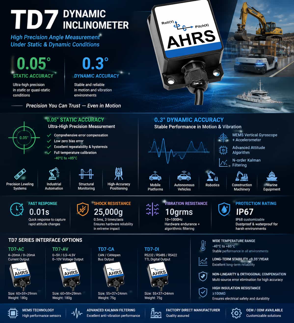
The TD7 series represents a new generation of high-performance dynamic inclinometers, available in four interface configurations: current output (TD7-AC), voltage output (TD7-AV), CAN output (TD7-CA), and digital output (TD7-DI). This series achieves high levels of accuracy in both dynamic and static measurement modes; the key accuracy parameters are detailed below. 1. Dynamic Accuracy vs. Static Accuracy The core accuracy specifications for the TD7 series are a dynamic measurement accuracy of 0.3° and a static accuracy of 0.05°. These figures reflect the sensor's performance under two distinct operating conditions. The dynamic accuracy of 0.3° represents the maximum error when measuring inclination in environments characterized by motion or vibration. The TD7 incorporates an internal vertical gyroscope and accelerometer, an integrated attitude solver, and optimal digital filtering for noise reduction. Combined with an N-order Kalman filter algorithm, it accurately outputs the object's attitude angles even amidst strong vibration and movement. This specification is critical for evaluating the sensor's suitability for applications involving mobile platforms, vehicles, robots, or vibrating machinery. The static accuracy of 0.05° represents the combined error under stationary or quasi-static conditions across the full operating temperature range of -40°C to +85°C. This figure encompasses errors arising from absolute linearity, repeatability, hysteresis, zero-point offset, and horizontal axis misalignment. A static accuracy of 0.05° is considered high-performance in the field of industrial inclination measurement. The nearly six-fold difference between these two values serves as a reminder that accuracy decreases during dynamic operation—an inherent characteristic of dynamic measurement systems. 2. Temperature Drift and Zero-Point Stability The zero-point temperature drift is ±0.01°/°C (for TD7-AC/AV models) or ±0.05°/°C (for TD7-CA/DI models). Taking the TD7-AC as an example, the zero-point may drift by approximately 0.6° when the ambient temperature shifts from 25°C to 85°C. For equipment operating outdoors or across wide temperature ranges, this parameter directly impacts long-term measurement reliability. The sensitivity temperature coefficient is ≤200 ppm/°C (TD7-AC/AV) or ≤150 ppm/°C (TD7-CA/DI). This parameter indicates the extent to which temperature fluctuations affect the sensor's "ratio of output change to angular change." A value of 200 ppm/°C means that for every 1°C change in temperature, the sensitivity undergoes a relative change of approximately 0.02% (two parts in ten thousand). The TD7 series employs various techniques—such as non-linearity compensation, orthogonality compensation, and temperature drift compensation—to eliminate sources of error, ensuring stable measurement performance across a wide temperature range of -40°C to +85°C. 3. Long-term Stability The long-term stability specification is <0.35°. This figure represents the maximum deviation between the sensor's output and its initial value after one year of continuous operation at room temperature. It implies that over the sensor's average service life of 55,000 hours (approximately 6.3 years), accuracy will drift slowly over time, with the maximum deviation remaining within 0.35°. 4. Interpretation of Key Response Time and Environmental Reliability Parameters Response Time (0.01s) This refers to the time required for the output to reach a stable, standard value following a step change in angle. A response speed of 0.01 seconds (10 ms) enables the sensor to track rapid changes in attitude in real-time. This makes it suitable for time-critical applications such as robotic motion control and dynamic marine navigation, serving as the temporal guarantee for achieving 0.3° dynamic accuracy. Shock Resistance (25,000g, 0.5ms, 3 shocks per axis) The sensor's internal MEMS structure sustains no permanent damage or zero-point offset after enduring an instantaneous shock of 25,000 times the acceleration due to gravity. This specification ensures that the device's long-term stability (<0.35°/year) remains unimpaired by accidental events like drops or collisions, acting as the first line of defense for hardware reliability. Vibration Resistance (10grms, 10–1000Hz) In environments subject to broadband random vibration (10–1000 Hz), the sensor not only withstands continuous stress at the hardware level but also effectively filters out vibration as noise using an N-order Kalman filtering algorithm. The synergy between hardware resilience and algorithmic filtering ensures the realization of 0.3° dynamic accuracy during motion. Ingress Protection Rating (IP67; IP68 customizable) IP67 indicates complete protection against dust and the ability to withstand short-term immersion (1 meter depth for 30 minutes), while IP68 meets requirements for long-term, continuous immersion. Featuring a matte-anodized aluminum alloy housing and sealed cabling, the unit effectively prevents moisture and dust ingress—which could otherwise cause circuit corrosion or degrade insulation performance (≥100 MΩ)—ensuring stable, long-term operation in harsh environments such as outdoor, bridge, and marine applications. 5. Model Differences All four models share essentially identical core accuracy specifications (dynamic: 0.3°; static: 0.05°), with the primary differences lying in their output interfaces: TD7-AC: 4–20 mA / 0–20 mA current output; TD7-AV: 0–5 V / 0.5–4.5 V / 0–10 V voltage output; TD7-CA: CAN/CANopen bus output; TD7-DI: Supports multiple digital interfaces, including RS232, RS485, RS422, and TTL. Additionally, the TD7-CA and TD7-DI models are more compact (55 × 37 × 24 mm) and lighter (75 g), whereas the TD7-AC and TD7-AV models measure 60 × 59 × 29 mm and weigh 180 g.
Read More
Technical Background: Transitioning from Static Measurement to Dual Static-Dynamic Modes Traditional inclinometers rely on MEMS accelerometers to measure the component of gravitational acceleration along a sensitive axis to calculate the angle, achieving high precision in static or quasi-static environments. However, when the host platform is subject to motion, vibration, or shock, external accelerations superimpose onto the gravitational acceleration, causing significant measurement distortion. This inherent limitation restricts the use of traditional inclinometers in dynamic scenarios such as mobile platforms, construction machinery, and robotics. The TD series of dynamic inclinometers fundamentally resolves this challenge through a fusion architecture combining a 3-axis MEMS accelerometer and a 3-axis gyroscope, alongside a dual-mode fusion algorithm that integrates static and dynamic capabilities. The core technology lies in the system's ability to assess the operating environment in real-time: in static mode, it employs a static algorithm to ensure ultimate precision; in dynamic mode, it automatically switches to a dynamic algorithm based on an N-order Kalman filter. By fusing the low-frequency stability of the accelerometer with the high-frequency response of the gyroscope, the system effectively suppresses measurement errors caused by vibration and shock. This technical approach enables the TD series to consistently output stable and reliable inclination data in complex dynamic environments. Product Matrix: Four Series with Differentiated Positioning The TD series addresses a wide range of needs, spanning from standard industrial-grade requirements to high-precision applications; the products are categorized into four tiers based on precision levels and application scenarios: Product Model Number of axes Static accuracy Dynamic accuracy Dimensions (mm) Positioning TD5 Three-axis 0.1° 0.5° 66×56×29 Standard industrial grade, dual dynamic/static modes TD6 Dual-axis 0.06° 0.5° 60×59×29 Dynamic type, high vibration resistance TD7 Dual-axis 0.05° 0.3° 55×37×24 High-precision dynamic, compact design TD9 Three-axis 0.02° 0.1° 78×44×26 Ultra-high precision, dual dynamic/static modes The TD5 series serves as a standard industrial-grade tri-axial inclinometer, offering a static accuracy of 0.1° and a dynamic accuracy of 0.5°. Featuring an integrated tri-axial accelerometer and gyroscope, it supports tilt monitoring across X, Y, and Z axes, with a measurement range of ±90° (tri-axial) or ±180° (optional single-axis). With a domestic content rate exceeding 85%, it is suitable for industrial applications such as forklift balance control, aerial work platforms, unloading machinery, and anti-tip protection for charging piles. The TD6 series is positioned as a purely dynamic dual-axis inclinometer, specifically designed for mobile platforms and high-vibration environments. It delivers a static accuracy of 0.06° and a dynamic accuracy of 0.5°, utilizing an integrated vertical gyroscope and an N-order Kalman filter algorithm. Error sources are eliminated through multiple techniques, including non-linear compensation, orthogonality compensation, and temperature drift compensation. With a Mean Time Between Failures (MTBF) of ≥55,000 hours and a shock tolerance of 25,000g, it excels in high-dynamic scenarios such as railway gauge measurement, bridge and dam monitoring, marine navigation attitude measurement, and wind turbine oscillation monitoring. The TD7 series represents high-precision dynamic inclinometers, boasting an improved static accuracy of 0.05° and a dynamic accuracy of 0.3°. Building upon the TD6, it features further optimized temperature drift control (≤150 ppm/℃) and a compact size of 55×37×24mm. It is ideal for applications demanding superior precision and compact dimensions, such as leveling control for precision machine tools, positioning for satellite solar arrays, and medical equipment. The TD9 series is the flagship of the TD lineup, offering exceptional static accuracy of 0.02° and dynamic accuracy of 0.1°. It incorporates a high-precision 16-bit A/D module and a temperature sensor, featuring a sensitivity temperature coefficient of ≤200 ppm/℃ and a shock tolerance of 5,500g. It supports tri-axial (X, Y, Z) tilt monitoring and is widely used in applications requiring extreme measurement precision, such as photovoltaic tracking systems, verticality monitoring for piling rigs, and vehicle overload monitoring. Output Interface Matrix: Comprehensive Coverage of Digital, Analog, and Bus Interfaces Another core advantage of the TD series is its comprehensive range of output interfaces. Each precision series offers three output types—digital, analog, and bus—allowing users to make flexible selections based on the requirements of their backend control systems: Digital Output (DI): Utilizes RS232, RS485, RS422, or TTL signal levels and supports standard Modbus RTU or custom hexadecimal protocols. Data is transmitted directly in digital format with high interference immunity, making it suitable for direct integration with digital systems such as PLCs and industrial PCs. Voltage Output (AV): Outputs an analog voltage signal, facilitating easy connection to traditional voltage-based data acquisition cards or instruments for direct signal reading and processing. Current Output (AC): Uses the industrial standard 4–20 mA current loop output. It offers strong interference immunity, making it particularly well-suited for long-distance transmission and harsh industrial environments. CAN Bus Output (CA): Supports the CAN 2.0 protocol, making it ideal for distributed control systems—such as those in automotive and robotics applications—that require high-speed bus communication. Core Technical Features The entire TD series shares the following core technology platforms: Dynamic-Static Dual-Mode Fusion Algorithm: The system automatically identifies its current operating state by analyzing acceleration and angular velocity data in real time. It employs a static algorithm during stationary periods to ensure maximum precision, and switches to a dynamic algorithm during movement, fusing gyroscope data to compensate for acceleration-induced interference. This mechanism enables a single sensor to handle two vastly different operating conditions: static installation and dynamic carrier applications. Comprehensive Temperature Compensation and Aging: Before leaving the factory, all products undergo rigorous calibration, temperature compensation, and long-term stability (aging) testing. The operating temperature range spans -40°C to +85°C, with a storage temperature range of -55°C to +100°C. Industrial-Grade Protection and Reliability: The entire series features an IP67 protection rating (IP68 available upon request) and comes standard with a 1.5-meter shielded cable that is wear-resistant, oil-resistant, and rated for a wide temperature range. Insulation resistance is ≥100 MΩ, and vibration resistance meets 10 grms (10–1000 Hz) standards. Flexible Communication and Power Supply: Output interfaces include options for RS232, RS485, RS422, TTL, and CAN bus, supporting both Modbus RTU and custom hexadecimal protocols. The wide input voltage range (DC 9–36 V, with 5 V optional) accommodates various power supply conditions found in industrial environments. Selection Recommendations The four products in the TD series form a comprehensive lineup covering a wide spectrum of specifications—ranging from standard industrial grade to ultra-high precision, 3-axis to 2-axis configurations, and general-purpose to compact designs. The TD5 serves as a cost-effective choice for standard industrial applications requiring 3-axis monitoring, while the TD6—with its optimization specifically for dynamic performance—is better suited for mobile platforms and high-vibration environments. The TD7 offers an optimal solution when both high precision and a compact footprint are required. Finally, for applications demanding the utmost precision—such as solar tracking and high-accuracy monitoring—the TD9 represents the pinnacle of domestic MEMS inclinometer technology, delivering a static accuracy of 0.02° and a dynamic accuracy of 0.1°. With a domestic content rate exceeding 85%, the series not only overcomes key technological barriers but also provides industries with complete tilt measurement solutions that span the full range from static to dynamic monitoring and from standard to high-precision performance.
Read More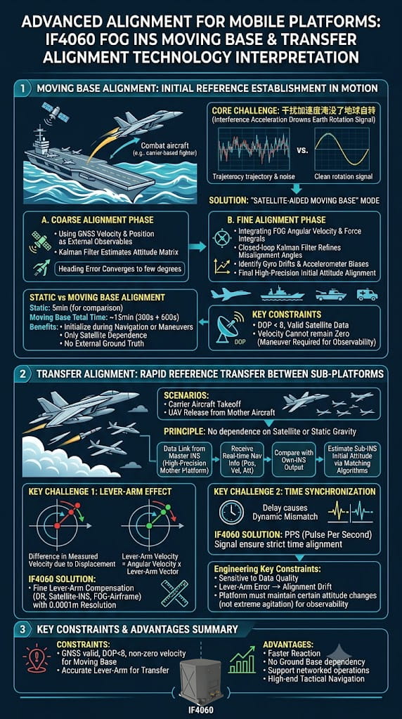
The IF4060 fiber-optic inertial navigation system (INS) not only possesses high-precision autonomous north-finding capabilities but also demonstrates exceptional tactical value through two advanced functions: dynamic base alignment and transfer alignment. These capabilities directly determine the system's rapid response and operational effectiveness when deployed on mobile platforms such as carrier-based aircraft, vehicle-mounted weapon systems, and UAV swarms. 1. Dynamic Base Alignment: Establishing an Initial Reference in a Swaying Environment The primary challenge of dynamic base alignment is that the disturbance accelerations caused by the carrier's motion overwhelm the reference signals—such as the Earth's angular velocity and the gravity vector—typically used for traditional analytical alignment. The IF4060 addresses this issue using a "satellite-aided dynamic alignment" mode, which operates in two stages: Coarse Alignment Stage: Velocity and position data from a satellite navigation system serve as external observations to construct a Kalman filter; this roughly estimates the attitude matrix and converges the heading error to within a few degrees. Fine Alignment Stage: Building upon the coarse alignment, this stage incorporates the INS's integrated angular velocity and specific force data. A closed-loop Kalman filter is used to refine the estimation of misalignment angles while simultaneously identifying gyro drift and accelerometer bias, ultimately achieving high-precision initial attitude initialization. Compared to static base alignment (5 minutes), dynamic base alignment takes approximately 15 minutes (300s + 600s). Although it requires more time, it allows for initialization while the platform is underway or maneuvering; furthermore, the alignment relies entirely on satellite navigation data without requiring an external ground-truth reference. The manual specifies that dynamic base alignment requires valid satellite data and a DOP value of less than 8. Additionally, the carrier's velocity cannot remain constant at zero—meaning a certain level of maneuver-induced excitation is necessary to ensure system observability. 2. Transfer Alignment: Rapid Reference Transfer Between "Parent" and "Child" Platforms Transfer alignment is another advanced feature of the IF4060, designed for "parent-child" platform scenarios—such as aligning carrier-based aircraft before takeoff or aligning a UAV before its release from a mother ship. Its operating principle relies neither on satellites nor static gravity; instead, it receives real-time navigation data (position, velocity, and attitude) from a master inertial navigation system (a high-precision host platform) via a data link. By comparing this data with the output of its own internal inertial navigation system and employing matching algorithms, it back-calculates its own initial attitude and navigation parameters. The core technical challenges of transfer alignment lie in the lever-arm effect and time synchronization. Because the slave and master inertial systems are installed at different locations, differences in linear velocity arise when the carrier maneuvers (lever-arm velocity = angular velocity × lever-arm vector). The IF4060 features a precise lever-arm compensation mechanism (handling DR-to-Inertial, GNSS-to-Inertial, and Inertial-to-Platform lever arms with a resolution of 0.0001 m). This mechanism translates the slave system's measurements to the master system's reference point, thereby eliminating matching errors caused by structural flexure and external lever-arm offsets. Simultaneously, the PPS (Pulse Per Second) signal ensures strict alignment of the time references between the master and slave systems, preventing dynamic mismatches caused by time latency. 3. Key Constraints for Engineering Implementation Both dynamic-base alignment and transfer alignment are highly sensitive to input data quality. During dynamic-base alignment, the system fails to converge effectively if the GNSS velocity reading remains constantly zero or the DOP (Dilution of Precision) value exceeds limits. In transfer alignment, if lever-arm parameters are incorrectly configured, a fault indicator will signal "excessive alignment drift." Furthermore, both alignment modes require the carrier to undergo a certain magnitude of attitude change during maneuvering—avoiding violent oscillation—to ensure the full-state observability of the Kalman filter. Summary The IF4060’s dynamic-base and transfer alignment capabilities essentially extend "static north-finding" to "filter-based estimation in dynamic environments" and expand "autonomous alignment" into "distributed cooperative transfer." These features elevate the IF4060 from a simple position/attitude sensor to a high-end tactical navigation node capable of rapid response within networked combat systems.
Read Moreleave a message
Scan to Wechat :
