




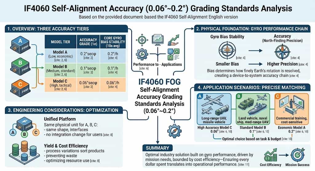
The IF4060 fiber-optic inertial navigation system is available in three models—A, B, and C—corresponding to low, medium, and high precision levels, respectively. Their self-north-seeking heading alignment accuracies (1σ) are 0.2°secφ, 0.1°secφ, and 0.06°secφ. This classification system is not arbitrary; rather, it is based on a comprehensive assessment of core component performance, application requirements, and cost-effectiveness. **Physical Basis for Precision Classification** Self-north-seeking accuracy is fundamentally determined by the bias stability of the inertial components. The gyroscopes in the three IF4060 models feature bias stabilities (10-second average) of 0.2°/h, 0.1°/h, and 0.06°/h, respectively. Gyroscope bias stability is the critical factor governing north-seeking accuracy: the lower the bias, the more precisely the gyroscope can resolve the Earth's angular velocity component, resulting in higher north-seeking accuracy. The three precision tiers correspond directly to the three levels of gyroscope performance, establishing a complete precision chain extending from the component level to the system level. **Industry Positioning of Precision Levels** From an industry perspective, a north-seeking accuracy of 0.06°secφ falls into the high-precision tactical category, capable of meeting demanding requirements such as precision guidance and autonomous UAV navigation. The 0.1°secφ level represents medium-precision tactical grade, suitable for applications like land vehicle and naval vessel navigation. The 0.2°secφ level targets applications that are cost-sensitive and have relatively relaxed precision requirements. Together, these three levels cover the entire spectrum of needs, ranging from "high-end/cutting-edge" to "economical/practical." **Engineering Considerations for Tiered Design** The strategy of offering three precision levels on a single platform reflects mature engineering principles. All three models share identical external characteristics—such as form factor and interfaces—allowing users to switch flexibly between precision levels without altering their system integration schemes. Regarding component selection, fiber-optic gyroscopes naturally exhibit performance variations during production; classifying and shipping products based on actual measured performance is the most economical and rational approach. This method prevents the waste of high-performance components while ensuring that every unit is utilized to its full potential. Precise Matching to Application Scenarios The 0.06° class is suited for missions requiring exceptional heading accuracy, such as long-range UAV reconnaissance and missile launcher alignment. The 0.1° class meets the needs of most tactical vehicles, naval navigation systems, and short-to-medium-range UAVs. The 0.2° class is appropriate for civil or training applications where cost control is strict and accuracy requirements are moderate. Users can select the optimal option from these three accuracy tiers based on mission requirements and budget constraints. The IF4060’s three-tier accuracy classification represents an optimal solution—grounded in gyroscope performance, driven by application needs, and balanced by cost-effectiveness—ensuring that every penny is spent where it counts most.
Read More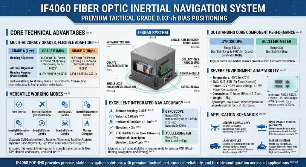
The IF4060 fiber-optic inertial navigation system (INS) is a single-axis rotation-modulated system primarily composed of a miniaturized fiber-optic gyroscope, quartz accelerometers, a servo mechanism, a power supply module, a data acquisition and processing module, and a satellite navigation module. Characterized by its compact size, light weight, high precision, and low cost, the product is capable of self-calibrating certain inertial component errors. As a high-end tactical-grade INS, the IF4060 is suitable for a wide range of demanding applications, including small-to-medium-sized UAVs and underwater robots. Core Technical Advantages 1. Multiple Precision Levels for Flexible Adaptation The IF4060 is available in three models—A, B, and C—corresponding to low, medium, and high precision levels, respectively; they share identical external characteristics, such as form factor and interfaces. Heading alignment accuracies are 0.2°secφ, 0.1°secφ, and 0.06°secφ (self-north-seeking), respectively; attitude alignment accuracy is 0.005° across all models; and heading hold accuracy (pure inertial mode) is 0.1°/h, 0.05°/h, and 0.03°/h, respectively. This three-tier precision design allows the IF4060 to flexibly meet the varying navigation accuracy requirements of different missions, handling everything from routine reconnaissance to high-precision strike operations. 2. Comprehensive Operating Modes The IF4060 supports multiple operating modes, including pure inertial, inertial/satellite, inertial/DVL, inertial/odometer, inertial/visual, and marine compass modes. It also supports functions such as self-north-seeking, transfer alignment, satellite-aided moving-base alignment, and high-precision post-processing. This comprehensive mode coverage ensures highly reliable navigation capabilities in complex environments—including GPS-denied, underwater, land, and aerial scenarios—fully meeting the adaptability requirements of tactical-grade products for complex battlefield conditions. 3. Excellent Integrated Navigation Precision In satellite-integrated navigation mode, attitude hold accuracy reaches 0.008°, velocity accuracy is 0.02 m/s, horizontal position accuracy is better than 1.5 m, and vertical position accuracy is better than 3 m. When utilizing a satellite carrier-phase differential link, the system achieves a horizontal accuracy of 1 cm + 1 ppm and a vertical accuracy of 2 cm + 1 ppm. This exceptional level of integrated navigation precision ensures the IF4060 fully meets the rigorous requirements for precise positioning, navigation, and timing (PNT) demanded by tactical-grade combat platforms. 4. Superior Core Component Performance The IF4060 is equipped with a gyroscope featuring a measurement range of 500°/s, a bias stability of up to 0.06°/h (10s average), and a bandwidth of 400 Hz; the accelerometer offers a measurement range of 30g and a bias stability of 50 μg. These high-performance inertial components provide a robust hardware foundation for the system's high-precision navigation capabilities. Adaptable to Harsh Environments and Tactical Demands The IF4060 operates within a temperature range of -45°C to +70°C, and its electromagnetic compatibility complies with the GJB151B standards for Air Force aircraft. It supports a wide input voltage range of 12V to 36V and consumes less than 12W of power. With dimensions of 118mm × 104mm × 117mm and a weight of only 1.8 kg, its lightweight, low-power, and wide-temperature design allows for flexible integration and deployment across various tactical platforms. Regarding interfaces, the IF4060 provides RS422, RS232, Ethernet, and PPS input/output ports, with customizable CAN interface options available. It supports a data update rate of up to 200 Hz, ensuring real-time responsiveness in highly dynamic operational scenarios. Application Scenarios Leveraging the aforementioned superior performance, the IF4060 fiber-optic inertial navigation system is widely used in: Small and medium-sized UAVs: Its lightweight design combined with high-precision navigation capabilities ensures reliable autonomous flight, target positioning, and engagement; Underwater robots: Integrated Inertial/DVL navigation and heave measurement capabilities meet the requirements for long-endurance, high-precision underwater navigation; Land vehicles: Integrated Inertial/Odometer navigation combined with an automatic north-finding function makes it suitable for tactical platforms such as armored vehicles and missile launchers; Marine systems: Marine compass modes and high-precision attitude measurement meet the needs of ship navigation and weapon system alignment. Conclusion With its single-axis rotation modulation technology, core components comprising high-performance fiber-optic gyroscopes and quartz accelerometers, flexible configuration across precision grades, comprehensive operational modes, and superior integrated navigation accuracy, the IF4060 establishes itself as a high-end tactical-grade inertial navigation system. Whether for UAVs, underwater robots, land vehicles, or marine systems, the IF4060 delivers precise and stable navigation solutions through exceptional performance, reliable environmental adaptability, and flexible configuration capabilities.
Read More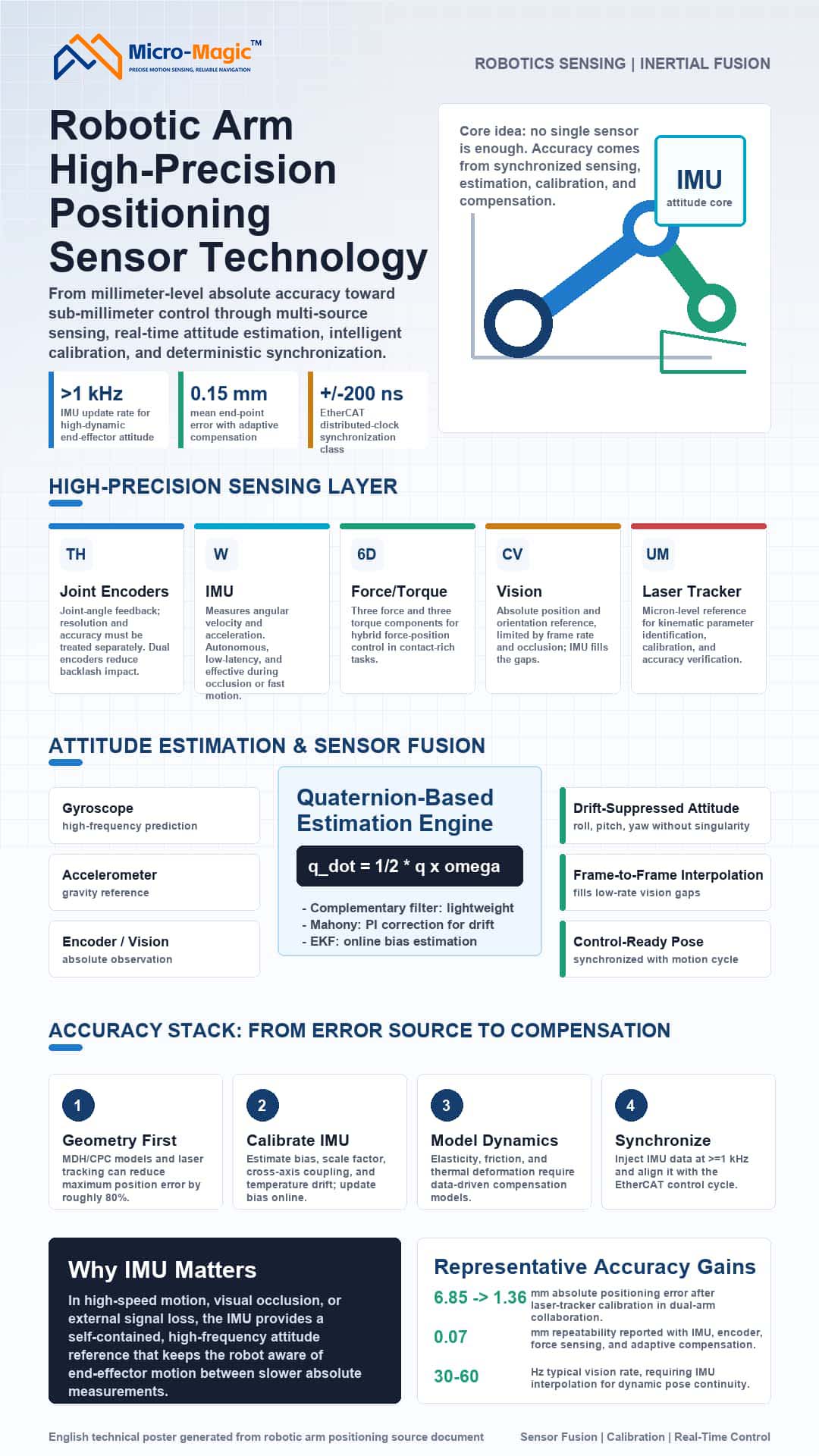
Introduction The absolute positioning accuracy of robotic arms—transitioning from the millimeter to the sub-millimeter scale—is constrained by multiple error sources: geometric parameter deviations (accounting for over 80%), sensor drift, elastic deformation, and communication jitter. Relying on single-sensor inputs or purely kinematic control is insufficient to meet the demands for dynamic, high-precision performance. Particularly during high-speed motion or in scenarios involving visual occlusion, the IMU—characterized by high-frequency operation, autonomy, and zero latency—serves as a cornerstone for pose estimation. Current technological trends favor a combination of multi-source sensor fusion, intelligent calibration, and high-real-time synchronization. High-Precision Positioning and Sensing Technologies Joint Encoders Encoders determine the accuracy of joint angle feedback. Key metrics: resolution and accuracy must not be conflated. Optical encoders can achieve an accuracy of 5 arcseconds and 23-bit resolution; magnetic encoders offer robust resistance to contaminants; and high-end systems employ dual-encoder setups to eliminate the effects of backlash. Inertial Measurement Units (IMUs)—The Core of Pose Estimation IMUs integrate tri-axial gyroscopes and accelerometers to directly measure the angular velocity and linear acceleration of the end-effector. Gyroscope integration yields relative pose data with update rates exceeding 1 kHz—far surpassing vision systems—while accelerometers provide an absolute gravity reference during static states to calibrate integration drift. However, IMUs suffer from gyroscope integration drift (which can reach 30° after 10 minutes of inactivity) and accelerometer motion noise; resolving these issues is the central challenge addressed by sensor fusion. The unique advantage of the IMU lies in its independence from external signals and immunity to occlusion or latency-induced jitter, making it an irreplaceable autonomous sensor for high-frequency pose sensing at the robotic arm's end-effector. Six-Axis Force Sensors These sensors simultaneously measure three force components and three torque components, enabling hybrid force/position control. With an accuracy of 0.5% and repeatability error of 0.1%, they are utilized in contact-based tasks such as precision assembly and grinding. Vision Systems Configured as either "eye-in-hand" or "eye-to-hand," binocular vision systems can achieve positional accuracy of 1.2 mm and orientation accuracy of 0.15°, though they are limited by refresh rates (30–60 Hz) and occlusion issues. IMUs can be used to perform high-frequency pose interpolation between visual frames. External Calibration Equipment A laser tracker (offering micron-level accuracy) serves as the reference tool for kinematic calibration, parameter identification, and accuracy verification. Attitude Estimation and Sensor Fusion Attitude Representation Methods Euler angles are intuitive but suffer from the gimbal lock problem; degrees of freedom are lost when the pitch angle θ = ±90°. Quaternions: q = q₀ + q₁i + q₂j + q₃k, satisfying q₀² + q₁² + q₂² + q₃² = 1. Rotation operation: p' = qpq⁻¹ Quaternions are singularity-free and allow for smooth interpolation, making them the standard attitude representation in modern robotic systems. The core of IMU attitude estimation lies in solving the quaternion differential equation. Fundamentals of IMU Attitude Estimation: Quaternion Differential Equation Updating the quaternion using angular velocity ω = [ωₓ, ωᵧ, ωᵨ]ᵀ: q̇ = ½ q ⊗ ω Discretization (first-order integration): qₖ₊₁ = qₖ ⊗ (cos(‖ω‖Δt/2), (ω/‖ω‖)sin(‖ω‖Δt/2)) This equation forms the basis for all IMU-based attitude estimation algorithms. Complementary Filtering and the Mahony Algorithm Complementary filtering fuses gyroscope integration (reliable at high frequencies) with accelerometer data (reliable at low frequencies): θ(t) = α·θ_gyro(t) + (1-α)·θ_acc(t) (α typically ranges from 0.98 to 0.995) The Mahony filter introduces PI closed-loop correction: gyroscope drift is compensated using an error term *e*—derived from the cross product of the accelerometer measurement *a_m* and the gravity reference *g_ref*—where *e* = *a_m* × *g_ref* and *ω_corr* = Kₚ*e* + Kᵢ∫*e*dt. This method is computationally efficient and widely used in embedded systems for real-time attitude estimation of IMUs mounted on robotic arm end-effectors. Extended Kalman Filter (EKF)—Optimal Fusion Framework The EKF uses gyroscope integration for prediction and accelerometer data (along with magnetometer and encoder-based forward kinematics) for observation. The state vector is defined as x = [qᵀ, b_gᵀ]ᵀ (attitude quaternion + gyroscope bias). Prediction: $\dot{\hat{x}} = f(\hat{x}, \omega_m - b_g)$, $P = FPF^T + Q$ Update (using accelerometer observations of the gravity vector): $K = PH^T (HPH^T + R)^{-1}$ $\hat{x}^+ = \hat{x} + K(z - h(\hat{x}))$ The EKF enables online estimation of gyroscope bias, significantly suppressing long-term drift. A tightly coupled EKF integrating IMU data with encoders or vision systems is the standard architecture for achieving high-precision pose estimation of robotic arm end-effectors. Multi-source Fusion Strategy Heterogeneous sensors are fused at the data, feature, or decision level. As a high-frequency internal sensor, the IMU is often combined with encoders (low-frequency, high-precision angular data), vision systems (absolute position but low frame rate), and 6-axis force sensors (contact information) to form either loosely or tightly coupled systems. Hybrid fusion is currently the mainstream approach for achieving micron-level precision, with the IMU providing an indispensable real-time reference. Error Analysis and Calibration Compensation Dominance of Geometric Errors The classical DH model relies on idealized assumptions. Extended models (such as MDH and CPC) introduce additional geometric parameters. Calibration using a laser tracker can reduce maximum positional error by approximately 80%. IMU Error Calibration MEMS IMUs require calibration for bias, scale factors, cross-coupling, and temperature drift. Accelerometers are typically calibrated using the factory six-position method, while gyroscopes are calibrated using rate turntables. In robotic arm systems, kinematic constraints (such as static phase detection) can be utilized to update IMU bias online, effectively suppressing integration drift. Laser Tracker Calibration Process The robot traverses a set of predefined points while the laser tracker records end-effector coordinates; kinematic parameter deviations are then identified and compensated for. Following calibration, the absolute positioning accuracy of the dual-arm collaborative robot improved from 6.85 mm to 1.36 mm. Non-geometric Errors and Dynamic Compensation Non-geometric factors—such as joint elasticity, thermal deformation, and friction—cannot be adequately described by traditional models. Data-driven calibration methods (e.g., neural networks, Gaussian processes) enable the learning of error mappings from measured data. Compensation models integrating IMUs, encoders, and six-axis force sensors, combined with adaptive control, can reduce the mean end-effector positioning error to 0.15 mm and achieve a repeatability of 0.07 mm. Real-time Communication and Multi-axis Synchronization Multi-axis coordination requires the deterministic transmission of control commands. The EtherCAT industrial Ethernet bus employs an "on-the-fly processing" mechanism; its Distributed Clock (DC) synchronization error is as low as ±200 ns, with a jitter of ±5 μs. IMU data must be fed into the master controller at a rate of ≥1 kHz via high-bandwidth interfaces (such as SPI) and aligned with EtherCAT cycles to ensure strict frequency synchronization between attitude fusion and motion control. Trends and Conclusions High-precision robotic arm positioning is evolving toward a paradigm of multi-modal sensing, AI-based dynamic compensation, and real-time edge computing. As the core component for high-frequency, autonomous attitude sensing, the IMU—deeply integrated with encoders, vision systems, and force sensors—will play an increasingly indispensable role in high-speed, highly dynamic scenarios. Achieving absolute positioning accuracy at the sub-millimeter or even micron level requires coordinated optimization across four layers: sensing, computation, calibration, and synchronization.
Read More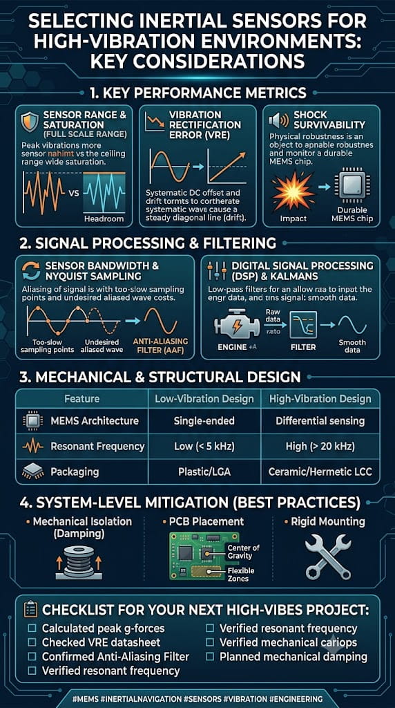
1. Introduction: Imagine a scenario where a welding robot operates continuously on an automotive assembly line, with the end of its robotic arm subjected to instantaneous shocks of 15g at a frequency of 80Hz. In this context, if the wrong IMU is selected, the bias drift of a standard sensor could accumulate to 1.2° within just 30 minutes, leading to positioning failure and a safety shutdown. This is no exaggeration. In high-vibration industrial environments—whether in stamping workshops, CNC machining, heavy-duty AGV operations, or heavy construction machinery—the challenge facing IMU sensors is not merely a matter of precision, but of fundamental viability. Vibration affects IMUs primarily through two channels: first, direct mechanical coupling, where vibration transmits through the mounting base to the sensor, interfering with the response of its micromechanical structure; second, Vibration Rectification Error (VRE), where the accelerometer’s DC rectification response to AC vibration generates an additional offset—a particularly critical issue for tilt-sensing applications. Furthermore, industrial environments experience drastic temperature fluctuations (-40°C to 85°C); since MEMS sensors are highly temperature-sensitive, an uncompensated gyroscope can exhibit bias drift on the order of ±10°/s. Therefore, selecting an IMU for high-vibration conditions requires addressing two core issues simultaneously: vibration interference resistance and temperature drift compensation. This article explores these two key aspects, systematically outlining the critical technical specifications and the decision-making process for product selection. 2. The Nature of Vibration Interference and Anti-Vibration Strategies 2.1. Understanding Vibration Rectification Error (VRE) In high-vibration environments, the most common failure mode for an IMU is not simply "inaccurate measurement," but rather "bias shift caused by vibration"—this is known as Vibration Rectification Error (VRE). For accelerometers, the sensor produces an unintended DC offset in response to AC vibration; such DC offsets are particularly detrimental in tilt-sensing applications. For gyroscopes, the primary issue is g-sensitivity, where linear vibration couples through the device's mechanical structure to superimpose a spurious angular rate signal onto the gyroscope's output. The combined effect of these issues can range from attitude drift to complete control system instability. 2.2. Mitigating Vibration at the Hardware Level When selecting products, priority should be given to IMUs featuring hardware-level vibration resistance designs rather than standard models that merely boast impressive specifications. The following vibration-resistant design features are key selection criteria: (1) Differential/Closed-Loop Sensing Architecture IMUs employing a differential gyroscope architecture can effectively suppress interference from linear acceleration and mechanical vibration. Closed-loop MEMS structures, combined with independent temperature compensation channels between the MEMS element and the ASIC circuitry, also significantly enhance vibration resistance. (2) Mechanical Filters and Vibration-Immune Designs Some industrial-grade sensors incorporate on-chip mechanical filters to attenuate high-frequency environmental vibration interference. For instance, Murata’s SCA3400 accelerometer utilizes a "vibration-immune design" capable of suppressing environmental vibration interference above 200 Hz. (3) Physical Isolation and Reinforced Packaging A dual-layer metal-ceramic housing combined with specialized damping materials can suppress mechanical noise coupling. The U4930 from Maixinmin Micro employs a hermetically sealed metal housing with specialized damping materials, suppressing mechanical noise interference while maintaining an IP67 protection rating. (4) Redundant Sensor Architecture A dual-IMU redundant architecture compensates for errors through real-time data comparison, further enhancing output reliability in high-vibration environments. 2.3. Suppressing Vibration Noise via Algorithms Even with optimal hardware selection, vibration noise cannot be entirely eliminated. Robust vibration-resistance solutions invariably incorporate noise reduction processing at the algorithmic level. (1) Adaptive Bandwidth Filtering One cutting-edge approach involves adaptive data preprocessing, where the filtering bandwidth is continuously adjusted via sinusoidal estimation to mitigate the impact of vibration and sensor noise prior to attitude estimation. Adaptive Kalman filter modules can dynamically adjust the noise covariance matrix and automatically optimize weighting based on external vibration frequencies, achieving an output noise density as low as 0.008°/s/√Hz. (2) Combination of Wavelet Filtering and Kalman Filtering Research indicates that by employing Gaussian-weighted moving average filtering combined with wavelet filtering for initial noise suppression, followed by PID-based fusion of the denoised data, and finally further optimization via Kalman filtering, the standard deviation of vibration noise can be reduced by 93.83%. (3) LMS and Extended Kalman Filter (EKF) Method For vibration scenarios such as vehicle bodies, the Least Mean Square (LMS) method can be used for front-end preprocessing to enhance the signal-to-noise ratio. Subsequently, the complementary characteristics of accelerometers and gyroscopes are utilized to filter out gyroscope bias noise, followed by final filtering using an Extended Kalman Filter. Results from a four-hour field experiment demonstrate that this method significantly reduces the impact of vehicle vibration on the IMU. 2.4. Key Selection Criteria for Vibration Environments When selecting a device, particular attention should be paid to the following vibration-related technical parameters: ` Vibration Rectification Error (VRE) / Vibration Rectification Coefficient: This is the most direct indicator of vibration resistance, typically measured in mg/g². Lower values indicate superior vibration resistance. ` Vibration Resistance: Expressed in grms (e.g., ≥20 grms or 10 g RMS over the 20 Hz–2 kHz range). ` Bandwidth Selection: Select a bandwidth that matches the target vibration frequency. An excessively wide bandwidth captures high-frequency in-band vibration, leading to higher VRE. Industrial-grade IMUs often intentionally limit output bandwidth to 100–200 Hz as an anti-aliasing design measure. ` Shock Tolerance: Typically required to be ≥2000 g or higher to ensure that accidental, severe shocks do not damage the IMU. 3. Temperature Drift Compensation Strategies and Accuracy 3.1. How Significant is the Impact of Temperature on IMUs? The sensitive structures of MEMS accelerometers and gyroscopes (such as silicon-based micromechanical beams, proof masses, and capacitive plates) undergo thermal expansion and contraction with temperature changes. This alters mechanical stiffness and capacitive gaps, resulting in output signal drift. For example, the Young's modulus of silicon decreases at a rate of approximately -60 ppm/°C as temperature rises; within the -40°C to 85°C range, the uncompensated bias drift of a gyroscope can reach the order of ±10°/s. Therefore, when selecting a device, one must focus on the IMU's stability across the full temperature range rather than relying solely on room-temperature specifications. 3.2. Technical Approaches to Temperature Drift Compensation Currently, there are two main technical paths for temperature drift compensation: Path 1: Hardware-level temperature compensation This involves integrating independent temperature sensors and compensation channels to monitor temperature and correct the output in real-time within the chip. Digital closed-loop systems are used to correct drift in real-time; for instance, the self-compensation feature in certain industrial-grade accelerometers can suppress temperature drift to ±0.003 mg/°C. Wafer-level encapsulation techniques and the selection of highly stable packaging materials help reduce thermal stress within the package. Path 2: Software/algorithm-level temperature compensation Software compensation relies on mathematical methods to analyze the relationship between temperature and the MEMS gyroscope's output data. It ensures output accuracy without incurring additional hardware costs, offering advantages such as simplicity, lower cost, and ease of parameter adjustment. Mainstream methods include polynomial fitting, piecewise linear/piecewise fitting, and interpolation techniques (such as Lagrange interpolation). Fundamentally, these methods predict and subtract temperature drift by establishing a mathematical mapping model between temperature and sensor error. The core concept involves using experimental data to train a function that maps temperature (or the rate of temperature change) to bias or scale factor corrections; during operation, the current temperature is input into this function to calculate the compensation value, thereby ensuring output stability across the entire temperature range. 3.3. Key Selection Metrics Related to Temperature Drift The following temperature-related parameters should be evaluated during the selection process: Full-temperature bias stability: Measures the variation in bias across the -40°C to 85°C temperature range, expressed in °/h or mg. High-quality industrial-grade IMUs can achieve a full-temperature bias of ≤150°/h (for gyroscopes). Bias temperature coefficient: Expressed in mg/°C or °/h/°C; lower values indicate better performance. For example, the accelerometer temperature offset is 0.026 mg/°C, while the gyroscope sensitivity temperature variation is only 0.0013%/°C. Temperature compensation method: Check the product specifications to see if they explicitly state the use of full-temperature-range calibration and compensation algorithms. Operating temperature range: Industrial grade is typically -40°C to 85°C, while more demanding applications may extend this range to -55°C to 125°C. 4. Selection Reference Based on Performance Grade For high-vibration industrial operating conditions, the following performance grade framework can be used as a reference for selection: Selection Grade Key Vibration and Temperature Compensation Characteristics Application Scenarios High-Performance Tactical Grade VRE 0.03 mg/g²; 10 g RMS vibration resistance; calibrated across the full -40°C to 71°C temperature range Robotics, navigation, stabilized platforms Industrial General-Purpose Grade -40°C to 85°C operating range; 0.026 mg/°C temperature drift; fault-tolerant design AGVs, agricultural machinery, precision GNSS Embedded Compact Grade Full-temperature compensation; ≥20 g RMS vibration resistance; ≥2000 g shock resistance Automotive, airborne, surveying and mapping High-Reliability/Long-Life Grade 10-year drift <0.5 mg; on-chip mechanical filter for vibration resistance (>200 Hz) Bridge monitoring, wind power, high-end equipment Redundant Dual-IMU Grade Dual IMU redundancy; IP67 protection; vibration damping; 0.5°/h bias stability Satellites, aerial surveying, harsh environments Summary When selecting an IMU for high-vibration industrial environments, the following key factors must be considered: (1) Vibration resistance: Focus on VRE (Vibration Rectification Error), vibration resistance ratings, mechanical filter design, and algorithmic noise reduction capabilities. (2) Thermal drift compensation: Focus on bias stability across the full temperature range, bias temperature coefficients, compensation algorithms, and wide-temperature calibration. (3) Comprehensive protection: Focus on shock resistance, IP protection ratings, and redundancy design. (4) Avoiding pitfalls: Relying solely on room-temperature specifications can be misleading; it is essential to request measured data regarding VRE and performance across the full temperature range. Ultimately, the selection of a suitable IMU should be based on a precise understanding of the specific application scenario—including vibration spectrum, temperature range, accuracy requirements, and installation space—alongside thorough communication with the supplier and, where necessary, empirical verification using prototypes.
Read More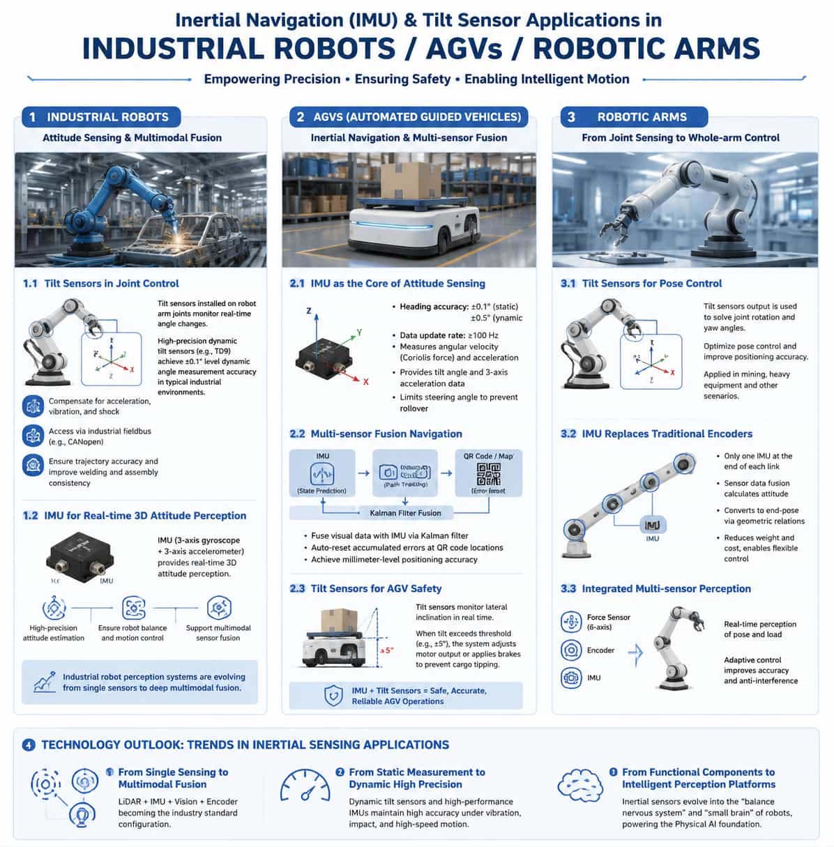
1. Introduction Driven by the wave of intelligent manufacturing and automation, industrial robots, Automated Guided Vehicles (AGVs), and robotic arms are becoming core execution units in modern industrial production systems. However, whether it involves high-speed AGVs navigating complex factory floors or multi-axis robotic arms performing micron-level operations during precision assembly, accurate attitude sensing and motion control are indispensable capabilities. Inertial Measurement Units (IMUs) and inclinometers serve as the core components that provide these devices with functions akin to a "sense of balance" and a "cerebellum." 2. Industrial Robots: Attitude Sensing and Multimodal Fusion Industrial robots operating in scenarios such as welding, assembly, and material handling demand extremely high precision and repeatability regarding motion trajectories. While traditional encoders provide joint angle information, relying solely on them often fails to meet high-precision control requirements—especially under conditions of high-speed movement, vibration, shock, or long-term operation. The introduction of inertial navigation sensors and inclinometers provides a new dimension of attitude sensing for industrial robots. 2.1. Application of Inclinometers in Joint Control In industrial robots, dynamic inclinometers installed at robotic arm joints monitor angular changes across various axes in real time. High-precision dynamic inclinometers—based on 3D MEMS accelerometers and gyroscopes—utilize intelligent algorithms to fuse signals from both sensors. This effectively compensates for the impact of acceleration, vibration, and shock on angular output. For instance, the TD9 model from Maixinminwei achieves dynamic angle measurement accuracy better than ±0.1° in typical industrial environments. Integrating such sensors into control systems via industrial fieldbuses (such as CANopen) enables real-time trajectory calibration, ensuring consistency in tasks like welding and assembly; in automotive manufacturing, this significantly improves the positional accuracy of vehicle body weld points. From a technical perspective, to address issues such as low measurement accuracy and complex control algorithms associated with industrial robot angle sensors, researchers have designed an accuracy analysis method based on smoothing filters. By applying a Savitzky-Golay filter to the raw data acquired by the sensors, output errors are effectively reduced. 2.2. IMU Provides Real-Time 3D Spatial Attitude Sensing The role of Inertial Measurement Units (IMUs) in industrial robots is becoming increasingly critical. An IMU typically comprises a three-axis gyroscope and a three-axis accelerometer; integrating gyroscope data yields changes in attitude, while combining this with accelerometer data allows for the calculation of accurate pitch and roll angles. High-performance MEMS IMUs provide robots with real-time 3D spatial attitude sensing, ensuring stability control and effective mobility. Precision inertial navigation technology is currently making rapid inroads into the industrial robotics sector. Automotive-grade IMU chips, utilizing advanced MEMS designs and ceramic hermetic packaging, offer high precision, high reliability, and stability across a wide temperature range. A trend toward the deep integration of LiDAR sensing and precision inertial navigation has emerged, with the two technologies being combined to develop multi-modal sensor fusion solutions for fields such as embodied AI and industrial robotics. This trend signifies a shift in industrial robot perception systems from single-sensor setups to deep multi-modal fusion. 3. AGV: Inertial Navigation and Multi-Source Fusion Positioning Automated Guided Vehicles (AGVs) are key components of logistics systems in smart factories; their navigation accuracy directly impacts material handling efficiency and production safety. Traditional navigation methods—such as magnetic strip guidance and QR code positioning—suffer from limitations like fixed paths, high deployment costs, and susceptibility to environmental interference. In contrast, the application of inertial navigation and tilt sensors has revolutionized AGV navigation. 3.1. The IMU as the Core of AGV Attitude Sensing The IMU is the core component enabling attitude and motion sensing in AGVs; without it, the vehicle would lose its ability to sense attitude, leading to motion control failure and a significant drop in operational precision. AGV-based IMU modules utilize three-axis MEMS sensors, achieving heading angle accuracy of ±0.1° in static conditions and ±0.5° in dynamic conditions, with data refresh rates typically exceeding 100 Hz. High-precision IMUs measure the Coriolis force via MEMS gyroscopes to accurately detect any angular velocity deviations from linear motion; simultaneously, their accelerometers provide data on the vehicle's tilt (inclination) relative to the horizontal plane and three-axis acceleration. Building on this, the system sets a maximum steering angle threshold to actively limit the steering range during turns, thereby effectively preventing rollovers. 3.2. Multi-sensor Fusion Navigation Single sensors have inherent limitations in complex environments: visual SLAM systems suffer from reduced localization accuracy due to dynamic environmental factors, while inertial navigation systems (INS) are prone to drift errors that accumulate over time. Consequently, multi-sensor fusion has become the mainstream solution for AGV navigation. In practical applications, INS signals are used for AGV state prediction, while path-tracking navigation and RGB-D visual navigation combine to form a multi-camera vision system that corrects accumulated INS errors through system observation. A Kalman filter algorithm fuses visual and inertial data, allowing accumulated errors to be automatically reset at QR code locations. An AGV navigation algorithm combining dual-PID control with inertial navigation technology achieves millimeter-level positioning accuracy via a dual-closed-loop control architecture, while simultaneously reducing the required density of QR code placement. In space-constrained environments with poor satellite signals—such as edible fungus factories—researchers have utilized Error-State Kalman Filters to fuse encoder and IMU data, achieving reliable navigation in narrow aisles and feature-sparse environments. In degraded environments like cable tunnels, visual-inertial SLAM algorithms based on point-line feature fusion effectively resolve localization challenges in settings with repetitive textures. 3.3. Inclinometers Ensuring AGV Operational Safety Inclinometers play a pivotal role in AGV anti-rollover systems. An inclinometer integrated into the AGV chassis dynamically monitors the vehicle's tilt angle during turns or load fluctuations; if the tilt exceeds a preset threshold (e.g., ±5°), the system immediately adjusts motor output power or applies the brakes to prevent cargo from tipping over. Inclinometers with high protection ratings (such as IP69K) are capable of withstanding harsh warehouse conditions, including wet floors and dust. 4. Robotic Arms: From Joint Sensing to Whole-Arm Control Robotic arms are core actuators in industrial automation, and their motion accuracy and flexibility directly determine production quality and efficiency. The application of inertial sensors and inclinometers in robotic arms is evolving from simple angle measurement toward full-state perception and intelligent control. 4.1. Precise Control of Robotic Arm Pose Using Tilt Sensors Tilt sensors play a crucial role in controlling the pose of robotic arms. An existing patented invention discloses a pose control method based on tilt sensors; by constructing a mathematical model and calculating the robotic arm's rotation and yaw angles from the sensor outputs, the method optimizes pose control and enhances positioning accuracy. This technology has already been applied in demonstration projects for intelligent coal mining operations. In heavy equipment such as coal mining roadheaders, mounting explosion-proof dynamic tilt sensors on the cutting boom allows for the measurement of the cutting head's pitch angle. When combined with angle sensors to measure the yaw angle, the system can obtain precise real-time data on the cutting head's orientation relative to the machine body. This system features a simple structure, ease of installation, and strong environmental adaptability. 4.2. IMUs Replacing Traditional Encoders Cable-driven linkage robotic arms feature slender bodies and flexible movement, enabling them to perform tasks such as inspection and maintenance in confined spaces and complex, unstructured environments. However, the large number of kinematic joints makes installing encoders at every joint costly; furthermore, if the robotic arm's outer diameter is too small, suitable encoders may not even be available. To address this challenge, a state-sensing and control method based on external IMUs was developed for cable-driven linkage robotic arms. An IMU is placed at the end of each linkage segment; sensor data fusion is used to calculate the IMU's orientation in real-time, which is then converted into the orientation of the segment's end based on geometric relationships. This approach effectively reduces the robotic arm's weight and enhances control flexibility. In the field of flexible robotic arms, multi-IMU sensor fusion frameworks are employed to estimate position and orientation. Flexible links are modeled as a series of rigid segments, with joint angles estimated using accelerometer and gyroscope data. Implementing closed-loop control via real-time IMU orientation feedback significantly improves the operational robustness and flexibility of the robotic arm. 4.3. Comprehensive Sensing via Multi-Sensor Integration Modern high-precision robotic arm motion control systems are evolving toward multi-sensor integration. By integrating six-axis force sensors, encoders, and IMUs, the system can sense the robotic arm's pose and load in real-time; when combined with adaptive sliding mode control algorithms, this integration significantly enhances motion accuracy and disturbance rejection capabilities. At the end-effector level, methods utilizing IMUs to acquire pose data in real-time can effectively compensate for pose deviations caused by joint torsion and connection errors. 5. Technological Outlook: Deep Multi-Sensor Fusion The application of inertial navigation and inclinometer sensors in industrial robots, AGVs, and robotic arms is characterized by three major trends: First, the evolution from single-mode sensing to multi-modal fusion. Since a single sensor cannot address all the challenges of complex industrial environments, multi-sensor fusion—combining LiDAR, IMUs, vision systems, and encoders—is becoming the industry standard. Second, the shift from static measurement to high-precision dynamic sensing. Traditional static inclinometers can no longer meet the demands of high-speed motion scenarios; conversely, dynamic inclinometers and high-performance IMUs fuse accelerometer and gyroscope data to maintain high-precision output even under conditions of vibration, shock, and rapid movement. Third, the upgrade from functional components to intelligent sensing platforms. Driven by the development of embodied AI and humanoid robots, inertial pose sensors are evolving from simple measurement elements into the "balance nerves" and "cerebellum" of robots. Relevant enterprises have established comprehensive technology and product ecosystems—spanning sensor chips, modules, and system assemblies—that serve as the "physical AI foundation" for robots and intelligent devices.
Read More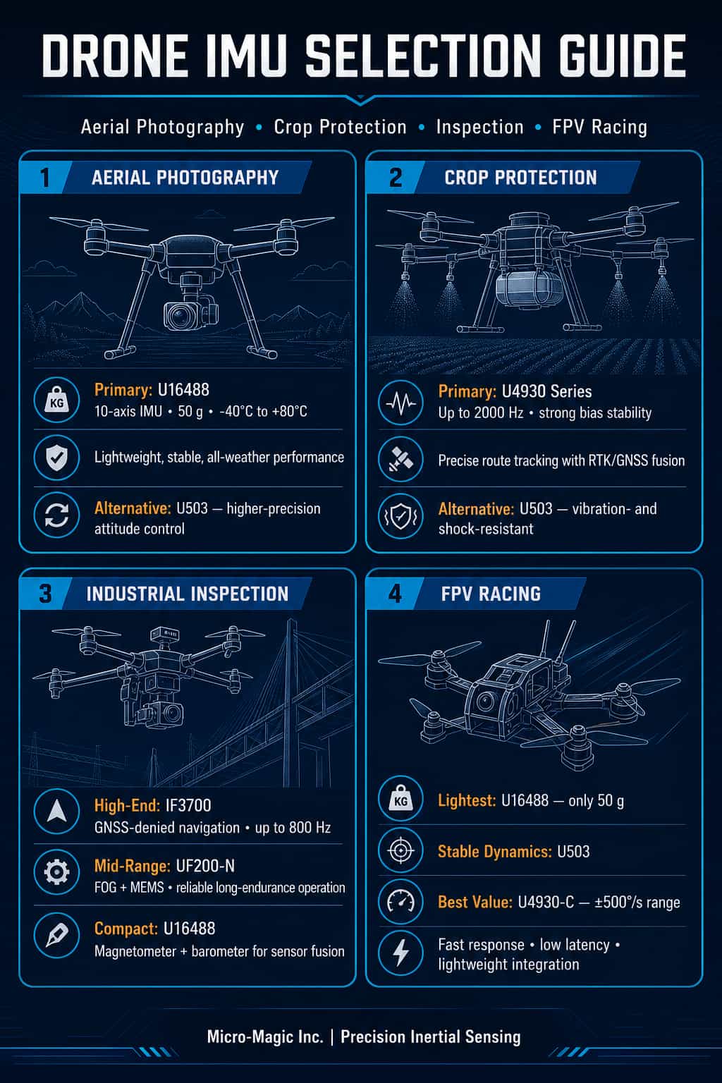
In the rapidly evolving drone industry, the Inertial Measurement Unit (IMU)—acting as the "sensory hub" of the flight control system—directly determines an aircraft's stability, precision, and reliability. Different application scenarios place vastly different demands on IMU performance: aerial photography drones prioritize ultra-stable image output; agricultural drones require precise flight path tracking; inspection drones demand long-duration, high-precision navigation; and racing drones prioritize dynamic response and lightweight design. As a leading domestic supplier of inertial sensors, Micro-Magic Inc. offers a comprehensive product portfolio ranging from MEMS inertial navigation modules to fiber-optic gyro systems, backed by extensive application experience in fields such as drones, autonomous driving, and robotics. This article focuses on four key drone segments—aerial photography, agricultural operations, inspection, and racing—and recommends the most noteworthy IMU models from Micro-Magic Inc. to assist developers in making precise product selections. I. Aerial Photography Drones: Ensuring Rock-Solid Stability in Every Frame For aerial photography drones, the core requirements for an IMU are high attitude accuracy, low noise, and excellent temperature stability. Whether for cinema-grade hexacopters or portable camera drones, the attitude data output by the IMU directly dictates the effectiveness of gimbal stabilization and overall image quality. Recommended Model: (1) U503 High-Precision 6-Axis MEMS Inertial Navigation Module The U503 is a high-precision, high-performance 6-axis MEMS inertial measurement module widely used in navigation, control, and measurement applications. Integrating high-performance sensors within a standalone unit—and featuring a hermetically sealed design and internal vibration damping—this module meets the rigorous demands of high-precision, high-dynamic navigation in harsh environments. In aerial photography scenarios, this ensures that the U503 provides stable, reliable attitude data to the flight controller even during strong winds or rapid maneuvers, effectively suppressing image jitter. (2) U16488 High-Performance MEMS IMU (Drop-in replacement for ADIS16488A) The U16488 is a high-precision, 10-axis MEMS inertial measurement unit integrating a tri-axial gyroscope, tri-axial accelerometer, tri-axial magnetometer, and barometer. It features a gyro bias instability as low as 0.5°/h (typical Allan variance) and an accelerometer bias instability of 20 μg. With its compact dimensions (47 × 44 × 14 mm) and lightweight profile (only 50 g), it is ideally suited for aerial photography drones with strict size and weight constraints. Additionally, the U16488 incorporates full-temperature calibration and compensation mechanisms, maintaining excellent measurement accuracy across a wide temperature range of -40°C to 80°C, thereby ensuring stable, high-quality aerial imagery output under diverse climatic conditions. II. Agricultural Spraying Drones: Precision Spraying Begins with Precision Sensing The operational characteristics of agricultural spraying drones dictate unique requirements for IMU performance: long-duration continuous operation, robust vibration resistance, and high-precision fusion with RTK/GNSS systems. Since these operations typically take place at low altitudes and low speeds in high-vibration environments, IMU bias stability and temperature drift control are critical. Recommended models: (1) U4930 Series High-Precision 6-Axis MEMS IMU (Drop-in replacement for HG4930) The U4930 series is a flagship industrial-grade MEMS inertial measurement module from Maixinmin Micro, available in three performance tiers: U4930-A, U4930-B, and U4930-C. The U4930-A model boasts a gyro bias instability as low as 0.03°/h, an angular random walk of only 0.02°/√h, and an accelerometer bias instability of 30 μg. This series supports a maximum data output rate of 2000 Hz and operates reliably within an ambient temperature range of -40°C to 80°C. For agricultural spraying drones, a 2000Hz update rate enables the real-time capture of even the slightest airframe vibrations and disturbances; combined with RTK/dual-antenna GNSS, this achieves centimeter-level flight path accuracy, effectively preventing overspraying or missed areas. Notably, the U4930 series serves as a direct drop-in replacement for the Honeywell HG4930, offering a cost-effective domestic alternative. (2) U503 (Also suitable for agricultural spraying applications) As previously mentioned, the U503 features internal vibration damping and exceptional vibration and shock resistance, making it ideally suited to the operational demands of agricultural drones, such as frequent takeoffs and landings and exposure to low-altitude vibrations. III. Inspection Models: Maintaining Heading in GNSS-Denied Environments Tasks such as power line, pipeline, and bridge inspections impose the most rigorous demands on IMUs, requiring long-duration pure inertial navigation capabilities, resilience against GNSS-denied conditions, and autonomous north-finding functions. Inspection drones often operate in areas where satellite signals are obstructed—such as near high-voltage towers, in canyons, or inside tunnels—requiring the IMU to independently maintain positional and attitude accuracy. Recommended Model: (1) IF3700 Satellite-Free Autonomous Navigation INS System The IF3700 is a high-end inertial navigation system developed by MaiXinMinWei specifically for satellite-free environments. It utilizes a high-precision closed-loop fiber-optic gyroscope (with a full-temperature bias stability of 0.01°/h) and a high-precision quartz accelerometer (20μg) to achieve high-precision pure inertial heading measurement. Its pure inertial performance is impressive: within one hour, the heading angle error is ≤0.01° (RMS), the attitude angle error is ≤0.005°, and the position error is ≤1 nautical mile/hour. In integrated navigation mode, heading accuracy is ≤0.02°, attitude accuracy is ≤0.005°, and RTK positioning accuracy is ≤2cm. It supports a maximum data update rate of 800Hz and offers multiple interfaces, including RS232, RS422, CAN, Ethernet, and USB. For aircraft such as large fixed-wing inspection drones and Vertical Take-Off and Landing (VTOL) UAVs, the IF3700 serves as a primary navigation unit. It maintains high-precision position and attitude output even when satellite signals are lost, ensuring the continuity and safety of inspection missions. (2) UF200-N High-Performance Fiber-Optic & MEMS Accelerometer Combined IMU The UF200-N is an Inertial Measurement Unit (IMU) based on high-precision fiber-optic gyroscopes and MEMS accelerometers. It adopts a modular design, offering high reliability and excellent cost-effectiveness. Its fiber-optic gyroscope features a measurement range of ±500°/s, a bias stability of 0.5°/h (10s smoothing), and an angular random walk as low as 0.02°/√h; the MEMS accelerometer offers a range of ±30g and a bias stability of 30μg. The UF200-N supports multiple interfaces, including RS422, RS232, and PPS; it has a steady-state power consumption of only 10W and weighs no more than 0.5kg. For medium-to-large inspection drones, the UF200-N provides high-precision, pure-inertial navigation capabilities within a lightweight package. It maintains stable position and attitude output even in complex environments where GNSS signals are unavailable, making it ideal for long-endurance missions—such as power grid and pipeline inspections—that demand strict precision and reliability. Additionally, its strong vibration and shock resistance allow it to fully meet the rigorous environmental requirements of industrial-grade inspection applications. (3) U16488 (Comprehensive Navigation with Magnetometer and Barometer) In addition to the high-precision MEMS IMU mentioned earlier, the U16488 integrates a three-axis magnetometer and a barometer, providing comprehensive environmental sensing capabilities. This makes it particularly suitable for inspection missions requiring multi-source data fusion: the magnetometer assists with heading calibration, while the barometer aids in altitude measurement, creating a triple-redundancy system that ensures the reliability of the inspection trajectory. IV. Racing Models: The Ultimate Pursuit of Speed, Precision, and Lightness The requirements for IMUs in racing drones (FPV drones) differ significantly from those in other applications: they demand ultra-high dynamic response, an extremely wide measurement range, minimal weight, and low-latency output. Every extreme roll, rapid dive, and instant acceleration pushes the performance limits of the IMU. Recommended Models: (1) U503 (Balancing Lightness and High Dynamics) Although positioned as a high-precision MEMS inertial navigation module, the U503 is designed with high-dynamic applications in mind. Its sealed housing and internal vibration-dampening design ensure stable attitude output even amidst intense vibration and shock. For professional-grade racing drones, it offers an ideal balance between precision and dynamic response capabilities. (2) U4930-B / U4930-C The U4930-B and U4930-C versions offer wider gyroscope measurement ranges (with the U4930-C reaching ±500°/s) while providing different trade-offs between bias stability and cost. For budget-conscious racing drone developers, the U4930-C delivers an ultra-wide ±500°/s range at a lower cost, fully capturing the high angular rate movements typical of competitive flight; meanwhile, the U4930-B version is available for professional racing models that demand higher precision. (3) U16488: The Ultimate Lightweight Choice Weighing just 50g, the U16488 is the lightest of the four recommended products—a crucial advantage for racing drones where every gram saved counts. Its dual SPI/UART communication interfaces also facilitate rapid integration with mainstream flight controller boards. V. Model Overview and Quick Selection Chart To facilitate quick comparison and selection, the table below summarizes the key features of the models recommended in this article: Model Product Type Key Advantages Data rate Weight Recommended Use Cases U4930 - A/B/C 6-Axis MEMS IMU Output rates up to 2000 Hz; high-precision accelerometer 2000 Hz 130g Plant protection, aerial photography U503 6-Axis MEMS IMU Internal shock absorption; resistant to vibration and shock 2000 Hz 220g Aerial photography, plant protection, racing U16488 10-Axis MEMS IMU Integrated magnetometer and barometer; ultra-lightweight design SPI/UART 50g Aerial photography, racing, inspection IF3700 Fiber-Optic INS/GNSS Integrated Navigation System Autonomous navigation without satellite signals; 0.003° attitude accuracy 800 Hz 7000g Inspection, industrial-grade aerial surveying UF200-N Fiber-Optic IMU Fiber-optic gyroscope and MEMS accelerometer; high reliability 200 Hz 500g Inspection, long-endurance flight VI. Model Selection Summary and Recommendations For aerial photography drones, the U16488 is the top recommendation; its ultra-lightweight design (50g) combined with full 10-axis functionality ensures a balance between image quality and flight endurance. If superior attitude accuracy is required, the U503 serves as an excellent alternative. For agricultural drones, the U4930 series is the primary choice. The U4930-A variant, in particular, offers the high stability and 2000Hz output rate needed to meet precision spraying requirements perfectly. Manufacturers requiring deep customization and integration can opt for the configurable version of the U4930A. For inspection drones, selection should be tiered based on budget and accuracy requirements: the IF3700 is the premier choice for high-end, large-scale drones, as its satellite-free autonomous navigation capability is crucial for inspection missions; the UF200-N (featuring a fiber-optic IMU) is suitable for mid-range models; and the U16488 is recommended for compact drones, offering the advantages of multi-source sensor fusion through its integrated magnetometer and barometer. For racing drones, balance is key. The U16488 represents the optimal solution for extreme weight reduction, while the U503 excels in stability during high-dynamic maneuvers; meanwhile, the U4930-C stands out as a cost-effective option offering an ultra-wide measurement range (±500°/s).
Read More
1. Introduction: Technological Landscape and Market Overview of Inertial Navigation Systems As an autonomous navigation technology that does not rely on external signals, Inertial Navigation Systems (INS) are experiencing unprecedented growth driven by the rapid advancement of frontier technologies such as artificial intelligence, autonomous driving, and commercial aerospace. Amidst fierce market competition and rapid technological evolution, Micro-Electro-Mechanical Systems (MEMS) and Fiber Optic Gyroscopes (FOG) have emerged as the two dominant technological pathways in the INS sector. Each offers distinct advantages; consequently, selecting the right technology for specific application scenarios has become a critical challenge for engineers and procurement teams. The choice between MEMS and FOG is not merely a contest of technical performance specifications but requires a comprehensive evaluation of mission duration, environmental conditions, precision thresholds, SWaP (Size, Weight, and Power) constraints, and budget. 2. Core Comparison: MEMS INS vs. Fiber Optic INS 2.1. Operating Principles and Technical Differences MEMS INS relies on micro-scale capacitive or piezoresistive structures to measure motion by detecting mechanical displacement; these systems can be packaged at the chip level, enabling low-cost, mass production. In contrast, Fiber Optic INS utilizes the Sagnac effect, employing kilometer-long optical fiber coils to detect rotation; its all-solid-state design ensures a long service life and resilience in extreme environments. The primary advantage of Fiber Optic INS is high precision—achieving bias stability as low as 0.001°/h and maintaining navigation capabilities for tens of minutes to several hours following a loss of GNSS signal. MEMS INS excels in extreme miniaturization, low power consumption, cost-effectiveness, instant startup, and high shock resistance. In recent years, the drift rate of tactical-grade MEMS has dropped to a few degrees per hour, and high-end products can maintain an attitude accuracy of 0.01° during a 60-second GNSS outage, steadily narrowing the performance gap with Fiber Optic INS. 3. In-depth Analysis of MEMS INS Application Scenarios 3.1. UAVs and the Low-Altitude Economy Consumer-grade and logistics drones represent key application scenarios for MEMS INS. In environments with weak GNSS signals—such as forests, underground parking facilities, and urban canyons—MEMS IMUs provide drones with continuous and precise pose (position and orientation) data. For small and medium-sized drones with flight times under 40 minutes, their lightweight and low-power characteristics align perfectly with SWaP (Size, Weight, and Power) requirements; furthermore, they have seen annual order growth exceeding 200% in emerging sectors such as low-altitude logistics and unmanned inspections. 3.2. Autonomous Driving and Smart Vehicles Intelligent driving has become the largest source of growth in the civil inertial navigation market. In practical applications, vehicles equipped with MEMS IMU modules can achieve continuous, precise positioning—keeping errors within 8 centimeters—even in areas where satellite signals are completely lost, such as three-level underground parking garages, thereby successfully executing autonomous parking. MEMS INS technology meets the precision requirements of most high-precision, industrial, and consumer-grade applications, offering "sufficient" accuracy through exceptional cost control. 3.3. Robotics and Physical Agents As the commercialization of intelligent equipment—such as humanoid robots, robot dogs, and AGVs—accelerates, market demand for inertial attitude sensors has experienced structural growth, given their role as the "balance nerves" and "cerebellum" of robots. When robots traverse complex terrain, GNSS signals may be interrupted; MEMS INS provides precise orientation to ensure stable operation. In industrial automation, MEMS INS has become an industry standard for tasks ranging from AGV autonomous navigation to industrial robotic arm attitude control, thanks to its compact size and low cost. 3.4. Precision Agriculture and Surveying While agricultural drones and autonomous farm machinery have relatively moderate requirements for navigation system precision, they demand high resilience against vibration, temperature fluctuations, and environmental contaminants. MEMS INS has become the mainstream choice in precision agriculture due to its excellent shock resistance and cost-effectiveness. From seeding monitoring to variable-rate fertilization, MEMS INS provides agricultural equipment with stable, reliable pose-sensing capabilities; moreover, the low cost per unit—compared to fiber-optic solutions—makes large-scale commercial deployment feasible. 4. In-depth Analysis of Fiber-Optic INS Application Scenarios 4.1. Aerospace and Defense Equipment Fiber-optic INS applications in the aerospace and defense sectors represent the "gold standard." Whether for high-dynamic tactical missiles, satellite attitude control, or navigation systems for large transport aircraft and fighter jets, fiber-optic gyroscopes (FOGs)—with their exceptionally low bias drift and superior long-term stability—remain indispensable core components. In the aerospace sector, fiber-optic inertial navigation systems (INS) operate independently of external radiation sources and are unaffected by geography, weather, or harsh environments; their operational scope spans aerospace, land surface, underground, open oceans, and even the deep sea. For instance, navigation and control systems for high-dynamic platforms based on FOG technology possess robust capabilities in vehicle navigation and control, finding widespread application in tactical missiles and satellite platforms. In the defense sector, FOGs serve as core components for strategic equipment such as missile guidance systems, military UAVs, and naval vessel attitude control systems, making them a key focus of international technology export controls. 4.2. Marine Navigation and Unmanned Underwater Systems For marine platforms such as deep-sea autonomous underwater vehicles (AUVs), unmanned underwater vehicles (UUVs), and surface vessels, satellite navigation signals often fail to penetrate the water; in such scenarios, fiber-optic INS becomes the sole navigation option. Fiber-optic INS can achieve a pure inertial navigation positional accuracy of better than 1 nautical mile (RMS) over one hour and a heading error of no more than 1 degree over 72 hours—capabilities that are critical for underwater missions lasting days or even weeks. State-of-the-art products also feature "north-seeking" capabilities, allowing them to rapidly determine true north in environments devoid of GNSS signals or free from magnetic interference, thereby serving as a cornerstone for shipborne navigation and underwater exploration. Fiber-optic gyro-based inertial navigation systems have become essential for maintaining mission stability in unmanned vehicles operating amidst high winds, complex terrain, and electronic warfare environments. 4.3. High-Speed Rail Track Inspection and Heavy Engineering High-speed rail track inspection imposes extremely stringent accuracy requirements on navigation systems, necessitating millimeter-level precision in the measurement of track geometric parameters. Thanks to their superior long-term stability and low-drift characteristics, fiber-optic INS units have become standard equipment on railway maintenance and inspection vehicles; these products are widely applicable across sectors ranging from high-speed rail track inspection to civil industries such as oil and gas, and coal mining. In scenarios where GNSS signals are completely unavailable—such as underground mines and tunnels—fiber-optic hybrid navigation systems have achieved positioning accuracy better than 0.1% of the distance traveled, maintaining stable, continuous operation in complex environments as deep as 1.4 kilometers underground. 4.4. Ocean-going Vessels and Offshore Platforms Navigation systems for ocean-going vessels must withstand months or even years of continuous maritime operation; any navigation failure could lead to catastrophic consequences. Thanks to their all-solid-state structure, absence of rotating friction components, exceptionally long service life, and high resistance to electromagnetic interference, fiber-optic INS units serve as a "trusted anchor" for marine inertial navigation. In high-precision applications such as offshore drilling platforms and dynamic positioning (DP) systems, fiber-optic gyro systems provide continuous attitude and heading references, ensuring the safety and efficiency of offshore operations. Offshore oil drilling platforms operating in the open ocean—where GNSS signals cannot be relied upon—also require the absolute orientation references provided by fiber-optic INS. 5. Integrated Selection and Decision-Making Framework Regarding cost, the significantly lower cost of MEMS INS has the potential to transition inertial navigation technology from a "military luxury" to the realm of civilian consumer products. A single tactical-grade MEMS system costs in the range of a few thousand dollars, whereas a navigation-grade fiber-optic INS can cost tens or even hundreds of thousands of dollars. If the project budget is limited and accuracy requirements are of moderate priority, MEMS INS is the more pragmatic choice. Regarding accuracy and stability, fiber-optic INS is required if positioning accuracy within a few hundred meters must be maintained for more than 30 minutes following a loss of GNSS signal. However, if mission durations are typically under 15 minutes and satellite signals are generally available, a high-performance MEMS INS is fully capable of handling the task. Regarding SWaP (Size, Weight, and Power) constraints, MEMS INS units are far superior to fiber-optic solutions, making them the ideal choice for drones, wearable devices, and microrobots. Although fiber-optic INS units have been significantly reduced in size through compact design, they still cannot compete with chip-scale MEMS in terms of miniaturization. Regarding environmental adaptability... MEMS INS offers exceptional shock resistance, making it suitable for applications involving vehicle turbulence or the intense vibrations experienced by drones; in contrast, fiber-optic INS excels in harsh environments characterized by extreme temperatures, high deep-sea pressures, and strong electromagnetic interference. Conclusion MEMS INS and fiber-optic INS represent two distinct evolutionary paths in inertial navigation technology. Leveraging the extreme integration of chip-based technology, MEMS has brought inertial navigation to mass-market civilian applications such as automobiles, drones, and robotics. Meanwhile, fiber-optic technology—drawing on the essence of all-solid-state optics—maintains the pinnacle of precision and reliability in cutting-edge sectors like aerospace, deep-sea exploration, and defense equipment. For engineers and procurement decision-makers, the crucial takeaway is that there is no single "best" technology—only the technology best suited to the specific application. A truly sound selection decision requires a balanced consideration of mission requirements, environmental challenges, and budget constraints.
Read More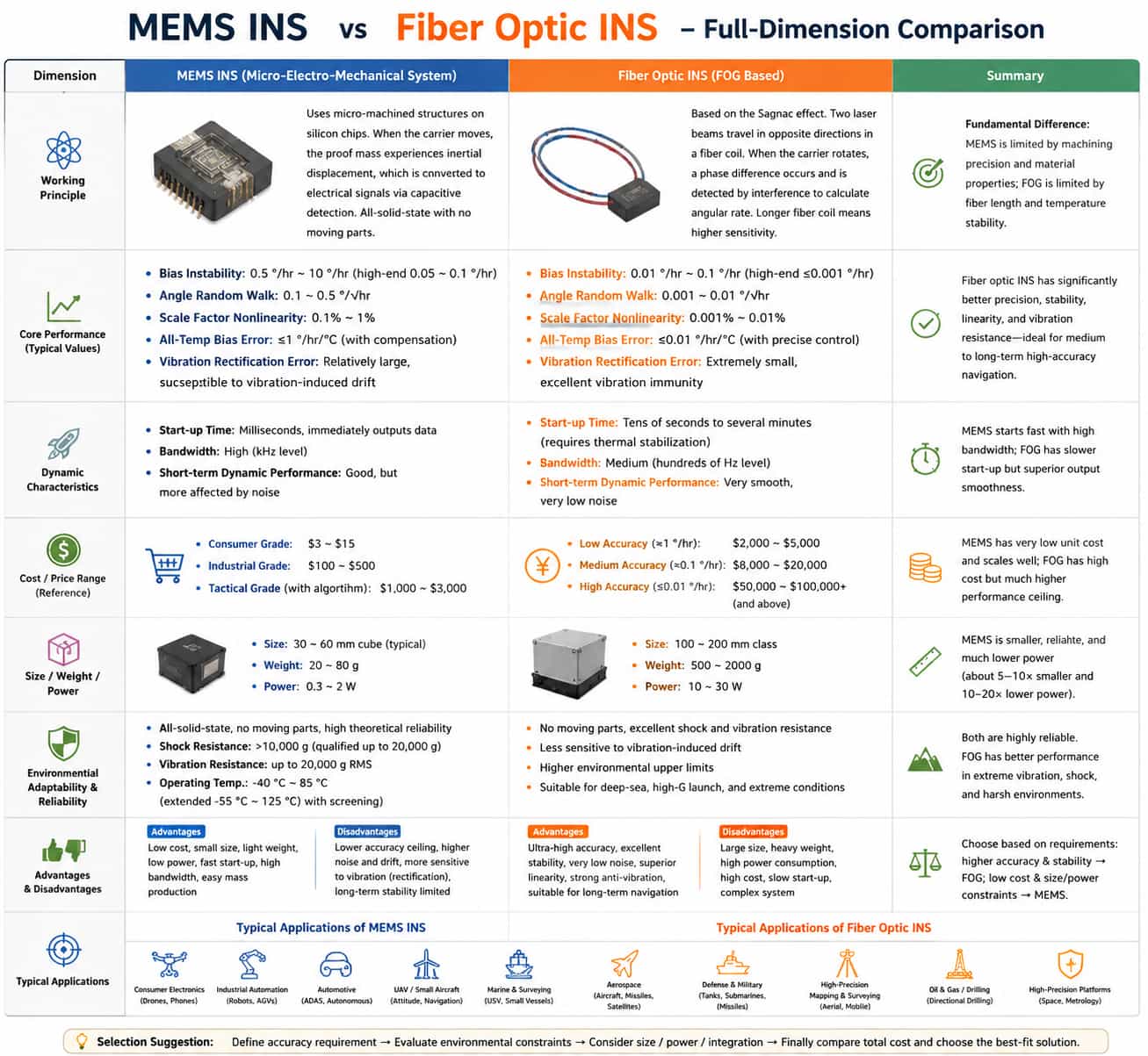
Current mainstream technical approaches for inertial navigation systems fall into two categories: MEMS-based inertial navigation (utilizing Micro-Electro-Mechanical Systems) and fiber-optic inertial navigation (based on optical interference principles). These two technologies differ fundamentally in their physical principles, performance metrics, cost structures, and application scenarios. This article provides a comprehensive, multidimensional comparison of these technologies to assist engineers in making informed decisions during the selection process. I. Fundamental Differences in Operating Principles MEMS inertial navigation systems employ silicon micromachining technology to fabricate movable micro-masses on a chip; when the carrier moves, inertial forces cause these masses to displace, generating electrical signals via capacitance changes—a fully solid-state design with no rotating parts. Fiber-optic inertial navigation systems rely on the Sagnac effect, where a laser beam is split into two beams propagating in opposite directions within a fiber-optic coil; carrier rotation creates an optical path difference between the beams, and angular velocity is calculated through interference detection. Sensitivity increases with the length of the fiber coil. These differences in principle dictate the inherent characteristics of each technology: MEMS systems function as "solid-state mass" sensors—insensitive to vibration but limited by manufacturing precision—whereas fiber-optic systems act as "optical interferometers," capable of high precision but significantly influenced by fiber length and temperature. II. Comparison of Core Performance Parameters Bias stability is the primary metric for measuring inertial navigation accuracy. Typical values for MEMS inertial navigation range from 0.5°/h to 10°/h; while high-end tactical-grade products can achieve 0.05°/h to 0.1°/h, they are approaching the technology's precision ceiling. In contrast, fiber-optic inertial navigation systems typically exhibit bias stability between 0.01°/h and 0.1°/h, with high-end products reaching 0.001°/h (arc-second level). Fiber-optic systems demonstrate a clear advantage in scenarios requiring pure inertial navigation over durations ranging from several minutes to tens of minutes. Angle random walk reflects the impact of white noise on attitude integration. Typical values for MEMS inertial navigation range from 0.1°/√h to 0.5°/√h, whereas fiber-optic systems can achieve values as low as 0.001°/√h to 0.01°/√h. This means that during short-term dynamic maneuvers, the attitude output from fiber-optic inertial navigation systems is smoother and exhibits less jitter. Scale factor nonlinearity: For MEMS inertial navigation systems, this typically ranges from 0.1% to 1%, whereas fiber-optic systems can achieve 0.001% to 0.01%. This nonlinearity advantage is crucial for high-dynamic maneuvers (such as those performed by missiles or fighter jets). Full-temperature bias error: MEMS silicon materials have high temperature coefficients; without compensation, the thermal drift of MEMS inertial systems can reach tens or even over a hundred °/h/°C. Modern high-end MEMS products utilize integrated temperature compensation and polynomial fitting to reduce thermal drift to within 1°/h/°C. Fiber-optic systems are also temperature-sensitive, but the temperature coefficient of the fiber coil itself can be partially mitigated through symmetrical winding techniques; combined with precise temperature control, the full-temperature error can be kept below 0.01°/h/°C. Vibration rectification error: MEMS inertial systems are prone to DC drift under high-frequency, intense vibration—an inherent flaw. Fiber-optic systems, lacking moving proof masses, exhibit excellent vibration resistance, maintaining accuracy far better than MEMS systems in vibrating environments. Startup time and response characteristics: MEMS inertial systems output data immediately upon power-up, with startup times in the millisecond range. Fiber-optic systems require a warm-up and stabilization period (typically ranging from tens of seconds to several minutes) because the light source and fiber coil must reach thermal equilibrium; otherwise, significant zero-point drift occurs. III. Cost Structure and Price Range MEMS inertial systems benefit from large-scale semiconductor manufacturing processes, resulting in very low unit costs. Prices range from $3–$15 for consumer-grade MEMS IMU chips, $100–$500 for industrial-grade modules (featuring temperature compensation and calibration), and approximately $1,000–$3,000 for tactical-grade MEMS inertial systems (including algorithms). The cost of fiber-optic inertial systems is primarily driven by the fiber coil, precision winding processes, the light source (SLD), and the photodetector. Fiber coils require high-precision winding, entailing high labor and equipment costs, and—unlike chips—cannot benefit from the same economies of scale to drive down prices. Low-precision fiber-optic gyroscope (FOG) modules (bias stability in the 1°/h range) are priced at approximately $2,000–$5,000; medium-precision units (0.1°/h range) cost about $8,000–$20,000; and high-precision units (0.01°/h range or better) can exceed $50,000–$100,000. Regarding cost structure, MEMS devices have extremely low marginal costs, making them suitable for mass deployment; conversely, fiber-optic inertial navigation systems (INS) have high per-unit costs, though their performance ceiling far exceeds that of MEMS. IV. Size, Weight, and Power Consumption High-precision industrial MEMS INS units typically feature a miniature modular design, often measuring just 30–60 mm on a side. Their compact structure—free of redundant optical components—allows for direct integration into wind turbine platforms or small host equipment with minimal installation footprint. In contrast, fiber-optic INS units incorporate fiber coils, laser sources, optical demodulation circuits, and thermal control structures; consequently, they generally measure 100–200 mm, occupy 5–10 times the volume of MEMS units, require significant installation space, and are unsuitable for integration into compact equipment. MEMS INS units utilize silicon-based MEMS technology, keeping the total weight generally between 20 g and 80 g. This ultra-light weight imposes no additional load on offshore floating platforms or lightweight mounting structures, making them ideal for lightweight installations and stress-free mounting. Fiber-optic INS units, however, feature complex optical structures and heavy metal housings and thermal insulation components, resulting in a total weight of 500–2,000 g. This substantial weight limits their use to heavy, fixed platforms and renders them unsuitable for monitoring scenarios requiring lightweight designs or strict load constraints. MEMS inertial navigation systems are driven by chip-based circuitry and operate with extremely low power consumption—typically just 0.3 to 2 W in a steady state. They support long-term battery operation and continuous (24/7) low-power monitoring, making them ideal for lightweight equipment deployed in remote field or open-ocean environments lacking a continuous power supply. In contrast, fiber-optic inertial navigation systems require continuous power for the laser source, optical signal demodulation, and temperature control modules. Their baseline operating power generally ranges from 10 to 30 W—dozens of times higher than that of MEMS systems—and they require auxiliary heat dissipation structures, limiting their use to fixed engineering platforms with stable mains power and ample power capacity. V. Environmental Adaptability and Reliability MEMS inertial navigation systems are all-solid-state devices with no moving parts, offering high theoretical reliability. However, under conditions of high shock (>10,000g) and intense vibration, the silicon proof mass may stick or fracture. Military-grade MEMS units, featuring specialized packaging, can withstand shocks of up to 20,000g. Their standard operating temperature range is -40°C to 85°C, which can be extended to -55°C to 125°C through screening. Fiber-optic inertial navigation systems also lack moving parts; since the fiber-optic coil is essentially made of glass fiber, it offers superior shock and vibration resistance compared to MEMS. However, the coil is sensitive to bending and stress, and improper packaging can lead to increased optical loss. Fiber-optic systems offer a higher ceiling for environmental adaptability, making them suitable for extreme conditions such as deep-sea submarine pressure, continuous ship motion, and high-G launch environments. Summary of Comprehensive Comparison MEMS inertial navigation systems excel in terms of size, weight, power consumption, cost, and startup speed, but lag behind in maximum achievable accuracy and resistance to vibration-induced drift. Fiber-optic systems excel in ultra-high accuracy, long-term stability, and resistance to environmental interference, but are less competitive regarding size, power consumption, cost, and startup time. There is no "right" or "wrong" choice—only the question of suitability: first determine accuracy requirements, then consider environmental constraints, and finally evaluate the economic factors.
Read More
A gyro north-finder is an inertial measurement device that utilizes the gyroscopic effect to sense the Earth's angular velocity of rotation, thereby autonomously determining the direction of true north. Unaffected by external magnetic fields and independent of satellite signals such as GPS, it provides a stable and reliable azimuth reference under harsh conditions—including environments with strong electromagnetic interference, underground spaces, and polar regions. Its core operating principle involves using a high-precision gyroscope to sense the Earth's rotational angular velocity vector; the angle between the carrier's reference axis and true north is then calculated and output as azimuth information. This article presents a systematic comparative analysis of gyro north-finders across four dimensions: accuracy definitions, technical standards, application scenarios, and key selection criteria. I. Accuracy Definitions: From Core Metrics to Comprehensive Evaluation Systems Regarding accuracy definitions, north-finding accuracy is expressed as a 1σ standard deviation, measured in degrees or arcseconds. A comprehensive evaluation should encompass absolute north-finding error, repeatability, circular linearity, and attitude measurement error. Fiber-optic north-finders can achieve static accuracy levels of 0.02° or even 0.001°; leveraging the Sagnac effect and all-digital closed-loop control, their bias instability can be as low as 0.002°/h. The performance of MEMS north-finders has improved significantly in recent years; high-end products have achieved bias instability better than 0.02°/h, with typical north-finding accuracy ranging from 0.5° to 1° (e.g., the Maixinminwei NF1100 achieves ≤1°×sec(L), while the NF1200 reaches 0.5°×sec(L)), and some miniature products can achieve 0.25° accuracy within three minutes. Fiber-optic solutions lead in absolute accuracy, whereas MEMS solutions offer advantages in size and cost. II. Technical Standards: A Multi-Level System Spanning Military Specifications to National Standards The technical standard system for gyro north-finders encompasses multiple levels—including national military standards, industry standards, and national standards—providing a comprehensive framework for product design, manufacturing, testing, and acceptance. Both fiber-optic and MEMS gyro north-finders must adhere to the requirements of this standard system; compliance is particularly stringent in the military sector, where the relevant standards carry greater mandatory force. At the national military standard level, GJB 2863A-2015, *General Specification for Gyro North-Finders*, serves as the guiding document. It stipulates general requirements, detailed requirements, and quality assurance provisions, acting as the fundamental basis for the development and production of all military-grade north-finders. At the national standard level, GB/T 45570-2025, *General Technical Requirements for Optical Gyroscopes*, is the latest released national standard. It covers product classification, technical requirements, test methods, and specifications for marking and packaging regarding fiber-optic gyroscopes and laser gyroscopes. Its Appendix B provides reference data on key performance indicators for typical fiber-optic gyroscope products, serving as a crucial technical basis for the design, production, and acceptance of fiber-optic north-finders. Additionally, some enterprises manage production in accordance with quality system standards such as ISO 9001:2008. At the gyroscope component level, GJB 10024-2021, *Test Methods for MEMS Gyroscopes*, specifies the test conditions, items, and methods for MEMS gyroscopes; it applies to functional and performance testing of MEMS gyroscopes used in inertial navigation, guidance, and control systems. GJB 8898-2017, *General Specification for Fiber-Optic Gyroscopes*, specifically standardizes the performance requirements and test methods for fiber-optic gyroscopes. III. Application Scenarios: Cross-Domain Applications Ranging from the Battlefield Frontline to Underground Engineering Gyro north-finders are applied across both military and civil sectors, covering a wide range of operational conditions—from static, high-precision referencing to dynamic, real-time orientation. Due to differences in performance characteristics and structural design, MEMS north-finders and fiber-optic gyro north-finders have distinct application scenarios. In the military sector, gyro north-finders are core equipment for the rapid and covert orientation of weapon systems. With their arc-second-level static accuracy, fiber-optic north-finders are widely used for high-precision alignment tasks involving artillery, missile launchers, radar antennas, and naval inertial navigation systems. Leveraging advantages such as compact size, low power consumption, and rapid startup, MEMS north-seeking instruments are seeing significantly increased application on lightweight weapon platforms. They facilitate rapid pre-launch alignment for missiles, rockets, artillery, and UAVs, and can even be embedded in handheld soldier terminals, underwater vehicles, and guided munition platforms—scenarios where fiber-optic solutions are difficult to implement. In environments characterized by electromagnetic interference or GPS denial, the fully autonomous and interference-resistant nature of MEMS north-seeking instruments makes them an ideal tool for covert orientation in mobile weapon systems. In the civil sector, fiber-optic north-seeking instruments are primarily used for directional control in tunnel shield tunneling, providing a stable true-north reference deep within tunnels where GPS signals are unavailable. In oil and gas exploration, they are installed near the drill bit to measure borehole azimuth and inclination in real-time; serving as a key technology for directional drilling, they achieve an accuracy of approximately ±0.1°. In geodesy and precision engineering, these instruments provide high-precision azimuth references for total stations and laser trackers, and are used for deformation monitoring of structures such as bridges and dams, achieving static accuracy of ≤0.02°. Thanks to their cost-effectiveness, miniaturization, and low power consumption, MEMS north-seeking instruments provide reliable orientation and attitude control in GPS- or magnetometer-free environments like coal mine tunneling and general mining operations; additionally, integrated MEMS systems can achieve a heading accuracy of 0.25° in railway trains. Overall, MEMS technology enables smaller, lighter north-seeking instruments that meet the needs of most civil industries with mid-to-high-level accuracy, making them particularly suitable for fields with constrained surveying environments. Regarding environmental adaptability, fiber-optic north-seeking instruments are sensitive to temperature fluctuations and bulky, requiring drift compensation when significant temperature gradients exist underground. Conversely, MEMS north-seeking instruments offer vibration and shock resistance and compact integration capabilities, though their high-temperature tolerance is limited to approximately 85°C. Consequently, fiber-optic solutions hold the advantage in scenarios involving continuous high-temperature downhole drilling. IV. Key Selection Considerations: A Comprehensive Trade-off Analysis When selecting between MEMS and fiber-optic north-seeking instruments, one must weigh multiple factors—including accuracy requirements, operating environments, dynamic characteristics, size and weight, cost budgets, and integration capabilities—as priorities vary significantly depending on the application scenario. Accuracy requirements dictate the technology choice: For high-precision applications requiring accuracy of ≤0.1°—such as shipborne inertial navigation system alignment or the establishment of high-precision geodetic benchmarks—fiber-optic north-seeking instruments are typically the only option, offering static accuracy of 0.02° or even 0.001°. Conversely, if the required accuracy falls between 0.2° and 1.0° and cost-sensitivity is a factor, MEMS is the superior choice; some MEMS products offer rapid alignment within 30 seconds (1° accuracy) or precise alignment within 90 seconds (0.5° accuracy), demonstrating clear advantages in dynamic response. Size, weight, and power consumption are increasingly critical factors in modern applications. MEMS north-seeking instruments can be miniaturized to approximately 40mm cubes, weighing less than 70g with power consumption as low as 1.5W, making them ideal for payload-sensitive platforms such as individual soldier equipment. Traditional fiber-optic instruments are significantly larger and consume more power; despite recent optimizations, they still lag orders of magnitude behind MEMS in these areas, making MEMS virtually the only viable technology for space-constrained applications. · Environmental adaptability is another key selection factor. MEMS north-seeking instruments offer superior vibration and shock resistance, making them suitable for dynamic platforms like vehicles and aircraft; neither technology is susceptible to magnetic field interference. Fiber-optic solutions hold the advantage in high-temperature environments (lacking semiconductor temperature limitations), making them particularly suitable for continuous high-temperature downhole drilling. While MEMS devices have slightly lower high-temperature tolerance, both technologies generally cover an operating temperature range of -40°C to +80°C. · Mechanical structure and indexing mechanisms also directly influence the selection decision. Fiber-optic north-seeking instruments utilize a single-axis gyroscope combined with a mechanical indexing mechanism; while they offer high static accuracy, their dynamic performance is limited, and they are prone to drift under vibration. In contrast, MEMS north-seeking instruments typically employ a three-axis strapdown configuration that eliminates the need for indexing mechanisms, resulting in superior dynamic response and vibration resistance; meanwhile, some low-cost single-axis MEMS models achieve cost reductions while maintaining accuracy through rotational modulation techniques. · Cost considerations are crucial during the selection process. Fiber-optic north-seeking instruments entail high initial procurement costs, with high-end models reaching hundreds of thousands of yuan. Conversely, MEMS north-seeking instruments benefit from semiconductor mass-production processes, offering significantly lower costs for equivalent accuracy. If accuracy requirements are not overly stringent and cost is the primary constraint, MEMS technology offers a clear economic advantage. Both technologies feature all-solid-state designs with manageable maintenance costs; however, MEMS devices offer higher levels of integration and typically exhibit lower failure rates. · Integration capabilities and communication interfaces represent key technical details in the selection process. Mainstream gyro north-seeking instruments support serial interfaces such as RS422, RS232, and CAN, with data output frequencies typically ranging from 100 Hz to 200 Hz; users should ensure compatibility with their host system's interface types and data protocol requirements. Regarding GNSS integration, some high-end products offer PPS synchronization input and TOV output functions, enabling time synchronization between inertial data and external satellite receivers. Selecting a gyro north-seeking instrument is a systematic process involving considerations of accuracy, cost, operating environment, dynamic characteristics, and integration. The MEMS and fiber-optic technological paths each possess distinct core advantages and operational limits; neither is inherently superior to the other. Users should conduct a comprehensive assessment of their mission requirements to strike an optimal balance between these two approaches: for strategic-level applications prioritizing maximum accuracy regardless of cost, fiber-optic north-seeking instruments remain the irreplaceable choice; for tactical-level and civilian scenarios prioritizing miniaturization, rapid response, and cost-effectiveness, MEMS north-seeking instruments offer a more pragmatic and flexible solution. As MEMS gyroscope accuracy continues to improve and fiber-optic gyroscope miniaturization technology advances, the boundaries between these two technologies are becoming increasingly blurred. Future selection decisions will likely focus more on the specific constraints of the mission scenario rather than on technological labels alone—a shift that will undoubtedly provide end-users with a wider range of options and superior cost-performance value.
Read More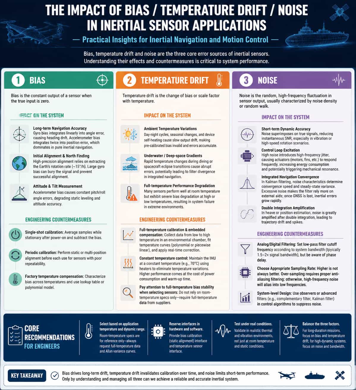
In inertial navigation and motion control projects, sensor bias, thermal drift, and noise are the three core error sources affecting system performance. The following section outlines their manifestations, impact on the system, and mitigation strategies from an engineering perspective. 1. Bias Bias refers to the constant static output of a sensor under zero-input conditions. In engineering applications, bias directly affects long-term integration accuracy and alignment capabilities: · Long-term navigation accuracy: Gyroscope bias accumulates linearly into angular error through integration; the higher the bias, the faster the heading drift. Accelerometer bias translates into position error through double integration, becoming a primary error source—particularly in pure inertial dead reckoning without external corrections. · Initial alignment and north-seeking: High-precision north-seeking requires extracting the north-pointing component from the Earth's angular velocity (approx. 15°/h); if gyroscope bias is excessive, the signal is overwhelmed, rendering effective alignment impossible. · Attitude and tilt measurement: Accelerometer bias directly causes constant offsets in pitch and roll angles, affecting static horizontal attitude accuracy. Engineering mitigation: · Single-event calibration/compensation: Perform static sampling and averaging after power-up, then subtract the constant offset value. · Periodic calibration: For sensors with poor repeatability, perform static-base or indexing alignment before each use. · Factory-level thermal compensation: Record bias values at various temperatures to establish lookup tables or polynomial models. 2. Thermal Drift Thermal drift refers to the variation in sensor bias or scale factor caused by temperature changes. In wide-temperature operating environments, errors induced by thermal drift are often one to two orders of magnitude larger than room-temperature bias: · Ambient temperature fluctuations: Diurnal temperature variations, seasonal changes, and equipment self-heating cause slow drift in sensor output, invalidating pre-calibrated bias values and leading to the accumulation of integration errors over time. · Underwater/deep-space temperature gradients: Rapid temperature changes—such as when a vehicle dives or a spacecraft enters/exits a shadow zone—can cause abrupt errors due to thermal drift, potentially leading to divergence in integrated navigation filters. Performance degradation across the temperature range: Many sensors exhibit excellent specifications at room temperature, but their zero-bias performance deteriorates significantly at high or low temperatures, potentially causing total system failure in extreme environments. Engineering countermeasures: · Full-temperature calibration + embedded compensation: Sensor output is captured in real-time within a thermal chamber across the operating temperature range; a temperature curve (polynomial or piecewise linear) is fitted, and the chip or navigation computer applies real-time corrections based on the current temperature. · Constant temperature control: In high-end applications (such as strategic-grade inertial navigation systems), heaters maintain the IMU at a constant temperature (e.g., 70°C) to eliminate temperature fluctuations, albeit at the cost of increased power consumption and longer startup times. · Prioritizing full-temperature zero-bias stability during selection: Many suppliers provide only room-temperature specifications—which can be misleading for a project—so it is essential to demand full-temperature performance data. 3. Noise Noise refers to random, high-frequency fluctuations in the sensor output, typically characterized by random walk coefficients or noise density. Its impact is primarily observed in short-term dynamics and system stability: · Short-term dynamic accuracy: Noise superimposed on the true signal reduces the instantaneous signal-to-noise ratio (SNR), an effect particularly pronounced during vibration or high-speed rotation. · Control loop excitation: High noise levels introduce high-frequency jitter, causing actuators (such as motors or control surfaces) to respond frequently; this increases energy consumption and may trigger mechanical resonance. · Integrated navigation convergence: In Kalman filtering, noise characteristics determine the convergence rate and steady-state variance of state estimates; excessive noise forces the filter to rely more heavily on external aiding data, meaning that if GNSS lock is lost, pure inertial errors will grow rapidly. · Double-integration amplification effect: In heave measurement or dead reckoning, noise is drastically amplified after double integration, resulting in trajectory drift or signal spikes. Engineering countermeasures: · Analog/digital filtering: Low-pass filter cutoff frequencies are set based on system bandwidth (typically 1.5 to 2 times the signal bandwidth), though this introduces phase lag. · Selecting an appropriate sampling rate: Higher is not necessarily better; oversampling necessitates anti-aliasing filtering to prevent high-frequency noise from aliasing into the low-frequency range. System-level design: Employ observers or higher-order filtering methods (such as complementary filtering or Kalman filtering) within control algorithms to suppress the impact of noise. 4. Key recommendations for project engineers · Select parameters based on the application's temperature and dynamic ranges; treat room-temperature specifications as reference only, and insist on obtaining full-temperature performance data and Allan variance curves. · Incorporate interfaces for bias compensation (static calibration) and temperature sensors into the hardware and software designs. · Conduct testing and validation under realistic thermal and vibration conditions, rather than relying solely on static tests at room temperature. · Balance bias, temperature drift, and noise: prioritize bias and temperature drift for long-endurance applications, and prioritize noise and bandwidth for high-dynamic applications.
Read More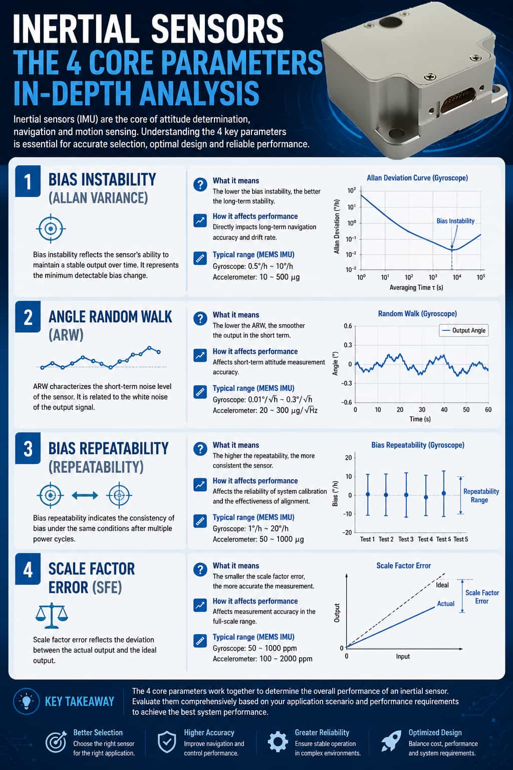
In the fields of inertial navigation, motion control, and high-precision attitude measurement, the performance of inertial sensors (gyroscopes and accelerometers) directly determines the upper limit of the entire system's accuracy. For engineers, understanding the practical significance of key parameters found in datasheets—and their impact on end-use applications—is essential for component selection and system design. This article provides an in-depth analysis of four core engineering parameters from a practical perspective: Bias Stability, Random Walk, Bias Repeatability, and Scale Factor Non-linearity. I. Bias Stability 1. Definition and Physical Significance Bias stability refers to the degree to which the sensor output fluctuates around its mean value under static conditions; it is typically characterized by the minimum point (or the flat region) on the Allan Variance curve. For gyroscopes, the unit is generally °/h (degrees per hour); for accelerometers, it is mg or μg. It reflects the stability of the sensor's output during prolonged static operation. A fiber-optic gyroscope with a bias stability of 0.01°/h implies that the fluctuation of its average output over one hour is approximately 0.01 degrees; this is a critical performance metric for navigation-grade inertial navigation systems. 2. Engineering Test Method Mount the sensor on a high-precision turntable, ensuring it remains absolutely stationary and the ambient temperature is stable (e.g., inside a temperature-controlled chamber at 25 ± 0.1°C). Continuously collect static data for several hours (at least 4 to 24 hours). Calculate the Allan Variance and extract the standard deviation at smoothing times (τ) such as 1s, 10s, and 100s; the optimal bias stability value corresponds to the transition point between the curve segment with a slope of -0.5 and the flat region. 3. Impact on the System Bias stability directly affects long-term navigation accuracy and determines the rate at which angular errors accumulate during inertial integration; for instance, a drift of 1°/h results in a heading error of approximately 1° over one hour. Furthermore, high-precision north-seeking requires extremely low bias stability (≤0.01°/h) to effectively extract the north-pointing component from the Earth's rotation rate (15°/h). 4. Engineering Misconceptions and Considerations Not all smoothing times adhere to the same standard; different manufacturers may report stability based on 10-second or 100-second smoothing, so the smoothing time must be standardized when making comparisons. Temperature effects far exceed static fluctuations; bias variation across the full operating temperature range can be one to two orders of magnitude greater than static stability. Therefore, engineering applications must focus on the equivalent stability achieved after full-temperature compensation. II. Random Walk 1. Definition and Physical Significance Random walk refers to the random error resulting from the integration of white noise. For gyroscopes, this is known as Angular Random Walk (ARW), measured in °/√h; for accelerometers, it is known as Velocity Random Walk (VRW), measured in m/s/√h or (m/s)/√h. It characterizes the energy intensity of high-frequency white noise in the sensor output. For a gyroscope with an ARW of 0.01°/√h, the standard deviation of the angular error introduced by white noise during a one-hour integration is 0.01° × √1 = 0.01°; however, if integrated for 0.01 hours (36 seconds), the error is 0.01 × √0.01 = 0.001°. The error is proportional to the square root of time. 2. Engineering Test Methods This parameter is also obtained via Allan variance analysis. At small values of τ (typically <10s), the random walk coefficient can be derived from the segment of the Allan variance curve with a slope of -0.5. Alternatively, it can be calculated by integrating the Power Spectral Density (PSD) within the relevant bandwidth. 3. Impact on the System Random walk primarily affects short-term dynamic accuracy; it superimposes noise and reduces the signal-to-noise ratio during vibration or high-speed rotation. Excessive random walk can excite the control loop, causing jitter, and—in integrated navigation systems—it affects the convergence rate and steady-state variance of the Kalman filter. 4. Engineering Misconceptions and Considerations Random walk and bias stability are independent yet related; random walk determines short-term noise, while bias stability determines long-term drift. Both must be optimized simultaneously, as focusing solely on the former may result in excessive long-term drift. III. Bias Repeatability 1. Definition and Physical Significance Bias repeatability refers to the consistency of a sensor's zero-point output across different startup events. It shares the same units as bias stability (°/h or mg). It reflects the sensor's predictability—both between batches and after each power-up. Sensors with poor repeatability require bias recalibration upon every startup; otherwise, a constant error (offset) will occur. 2. Engineering Test Methods Under identical environmental conditions, perform multiple power-up tests (≥10 times) on the same sensor, recording the stabilized bias value each time. Calculate the standard deviation (1σ) or the range (maximum minus minimum) of these bias values. 3. Impact on the System Bias repeatability determines whether the sensor requires recalibration upon each startup. If repeatability is superior to the system's allowable error, factory calibration values can be used directly; otherwise, a self-calibration process must be implemented. Furthermore, in multi-redundant configurations, repeatability directly affects consistency among sensors, thereby determining the complexity of the voting logic. 4. Engineering Misconceptions and Considerations It is crucial to distinguish between repeatability and stability: stability measures fluctuations during operation, whereas repeatability reflects shifts between different operational cycles. Even with extremely high stability (e.g., 0.01°/h), poor repeatability renders a sensor unsuitable for direct use in high-precision navigation. Compared to MEMS sensors, quartz accelerometers can achieve bias repeatability of less than 50 μg, making them particularly suitable for high-end applications requiring long-term, calibration-free operation. IV. Scale Factor Non-linearity 1. Definition and Physical Significance Scale factor non-linearity refers to the degree to which the proportional relationship between changes in sensor output and input deviates from an ideal straight line; it is typically expressed as a percentage of full scale (% FS) or in parts per million (ppm). For example, a range of ±500°/s with 50 ppm non-linearity implies a maximum non-linearity error of 500 × 50 × 10⁻⁶ = 0.025°/s. This parameter determines the sensor's measurement fidelity across a wide dynamic range (e.g., high rotation rates or high accelerations). 2. Engineering Test Methods Mount the sensor on a rate table (for gyroscopes) or a centrifuge (for accelerometers). Apply various input rates (e.g., 0, ±50, ±100, ±200, ±500°/s) and record the outputs. Fit a straight line using the least-squares method, calculate the maximum deviation of the measurement points from this line, and divide by the full-scale range to obtain the non-linearity value. 3. Impact on the System Scale factor non-linearity can become a primary source of error in high-dynamic scenarios (such as missiles or high-performance aircraft); even after multi-point calibration, non-linearity can still result in interpolation residuals. Furthermore, accelerometer non-linearity affects velocity integration accuracy, particularly during prolonged, high-maneuverability operations. 4. Engineering Pitfalls and Considerations When evaluating scale factor non-linearity, note that the absolute error value is directly related to the measurement range; one cannot judge performance based solely on the ppm value (e.g., 100 ppm yields an error of 0.01°/s at a 100°/s range, but increasing the range tenfold increases the error tenfold). Additionally, asymmetry between positive and negative directions is critical for rotationally symmetric platforms. Temperature also significantly influences non-linearity; variations across the full operating temperature range often exceed values measured at room temperature, necessitating temperature compensation. Summary When selecting components for engineering applications, avoid pursuing the "best" value for a single parameter in isolation. Instead, comprehensively weigh the four core parameters by considering system error allocation, the operating environment, calibration cycles, and cost constraints. At the same time, it is essential to require suppliers to provide Allan variance curves and full-temperature performance plots, rather than merely typical values. Only by deeply understanding the underlying physics and error propagation characteristics associated with these parameters can one design truly robust, high-performance inertial systems.
Read More
I. Brief Overview of IMU Underlying Architecture The core hardware of an Inertial Measurement Unit (IMU) consists of accelerometers and gyroscopes, which measure linear acceleration and angular velocity, respectively. Industrial-grade and higher-tier IMUs typically employ MEMS technology, while high-end units utilize fiber-optic or laser gyroscopes, paired with dedicated ASICs to perform signal conditioning, temperature compensation, and preliminary filtering. Accelerometers are based on a "spring-mass" model—where the displacement of a proof mass reflects acceleration; gyroscopes leverage the Coriolis effect—where a vibrating mass generates a measurable deflection when subjected to rotation. At the algorithmic level, the Extended Kalman Filter (EKF) fuses these two data streams: the gyroscope provides high-frequency attitude tracking, while the accelerometer (along with the magnetometer) performs long-term correction for drift. Pure inertial navigation derives attitude by integrating angular velocity and position by double-integrating acceleration; however, measurement errors amplify rapidly with each order of integration, resulting in "drift." Consequently, IMUs are typically classified into grades based on their bias stability: 1) Industrial Grade (Bias Stability: 1–10°/h): Suitable for short-duration dynamic scenarios—such as industrial robots, AGVs/AMRs, automated production lines, and high-end rehabilitation equipment—where there is a moderate requirement for long-term stability but significant sensitivity to cost. 2) Tactical Grade (0.1–1°/h): Suitable for applications requiring high dynamic response and short-duration autonomous navigation, such as missiles, UAVs, unmanned ground vehicles, eVTOL aircraft, and tactical weaponry. 3) Navigation Grade (0.001–0.1°/h): Suitable for missions requiring autonomous navigation over medium durations (ranging from tens of minutes to several hours) without external calibration, such as those involving commercial or military aircraft, ships, and medium-to-long-range missiles. With an understanding of this underlying architecture, the application logic for IMUs across various industries becomes clear: fundamentally, it involves making distinct trade-offs among "precision, real-time performance, reliability, and cost." II. Underlying Application Logic Across Various Industries 1. Autonomous Driving and High-Precision Positioning In autonomous driving and high-precision positioning scenarios, the core requirement is to achieve continuous positioning—particularly in GPS-denied environments such as tunnels and underground parking garages. The application logic involves utilizing the IMU as a reliable baseline for short-term positioning. This data is fused with inputs from GNSS, wheel odometers, and vision/LiDAR systems via tightly coupled Kalman filtering. By leveraging the high-frequency motion priors provided by the IMU (specifically angular velocity and acceleration), the system can maintain sub-meter-level position estimation for periods ranging from tens of seconds to several minutes even after GPS signals are lost. Simultaneously, through redundant design (e.g., equipping a single Level 4 autonomous vehicle with three IMUs), the system ensures safe degradation in performance in the event of a single-point failure. The fundamental logic here is to trade the cost of short-term integration drift for full-scenario availability. 2. Drones and eVTOLs In drone and eVTOL scenarios, flight control systems read angular velocity and acceleration data from the IMU at frequencies of several hundred Hertz, using a PID closed-loop mechanism to adjust motor speeds in real-time. When GPS signals are robust, the IMU assists with position control; however, in GPS-denied environments (such as indoors or within canyons), the IMU combines with barometers or optical flow sensors to enter a pure inertial navigation mode. For manned aircraft such as eVTOLs, additional requirements include compliance with airworthiness standards (e.g., DO-160G) and the adoption of redundant architectures (e.g., equipping a single aircraft with six IMUs). The core logic in this context is characterized by "high frequency, low latency, and short-term autonomy." 3. Industrial Robots and Mobile Robots The core requirements for industrial robots and mobile robots are precise position control and long-term stability, aimed at enhancing repetitive positioning accuracy and the robustness of SLAM (Simultaneous Localization and Mapping) systems. In industrial robotic arms, tactical- or navigation-grade IMUs monitor the motion trajectories of individual joints in real-time, providing closed-loop corrections to motor commands to achieve a repetitive positioning accuracy of ±0.02 mm. In AGVs (Automated Guided Vehicles) and AMRs (Autonomous Mobile Robots), the IMU provides the SLAM system with continuous, short-term motion priors; when LiDAR systems fail due to occluded fields of view or insufficient environmental features, the integrated data from the IMU "bridges" these information gaps, thereby maintaining the continuity of pose estimation. The fundamental logic here is "high-precision short-term estimation to fill sensor blind spots." 4. Defense and Aerospace The core requirements in the defense and aerospace sectors are full-lifecycle reliability in extreme environments and autonomous navigation capabilities that function for extended periods without external calibration. Strategic-grade (or navigation-grade) IMUs—typically utilizing fiber-optic or laser gyroscopes—are designed to serve as completely independent sources of information. Their underlying logic is rooted in a combination of "full-spectrum error modeling" and "thermodynamic compensation." During critical phases such as launch, flight, or underwater submersion, these IMUs must withstand high g-forces, wide temperature fluctuations, and intense electromagnetic interference; simultaneously, through exceptionally precise bias stability and random walk specifications, they ensure that positional errors remain bounded over durations spanning hours or even months. Furthermore, domestic production and technological autonomy have become absolute imperatives within this field. 5. Medical Surgery and High-End Rehabilitation The core requirements in medical surgery and high-end rehabilitation are a high dynamic range and high repeatability in the quantification of biomechanical parameters. In orthopedic surgical navigation, IMUs are affixed to surgical instruments or the patient's skeletal structure; utilizing six-degrees-of-freedom (6-DOF) pose tracking, they map the real-time position of the instruments onto pre-operative medical images. The underlying logic here is to leverage the short-term precision of tactical-grade IMUs to circumvent the occlusion-sensitivity issues inherent in optical navigation systems. In gait analysis, IMUs are worn on the limbs to capture parameters such as joint angles and acceleration; these data are then processed via sensor fusion algorithms to generate clinical metrics such as step frequency and gait symmetry. Fundamentally, this application represents "wearable, wireless, and high-dynamic-range motion quantification." Summary The fundamental application logic of IMUs across various industries can be broadly summarized as follows: leveraging their inherent advantages—specifically their independence from external signals and their high-frequency response capabilities—to address either the "problem of spatiotemporal continuity in GPS-denied environments" or the "problem of real-time closed-loop control of motion states," all within a specific, requisite level of precision. The varying requirements across different industries—regarding bias stability, dynamic range, and environmental adaptability—dictate the specific selection of IMUs, ranging from tactical-grade to strategic-grade devices. Nevertheless, the shared engineering logic underpinning all these applications remains constant: trading off a controllable degree of integration drift in exchange for an indispensable capability for autonomous situational awareness.
Read Moreleave a message
Scan to Wechat :
