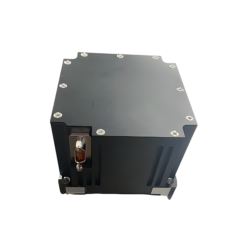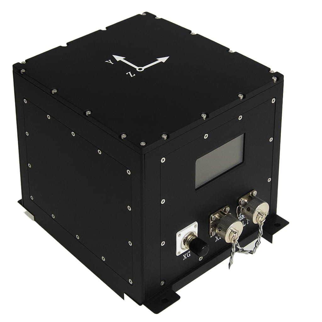
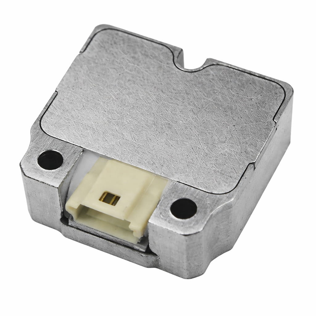
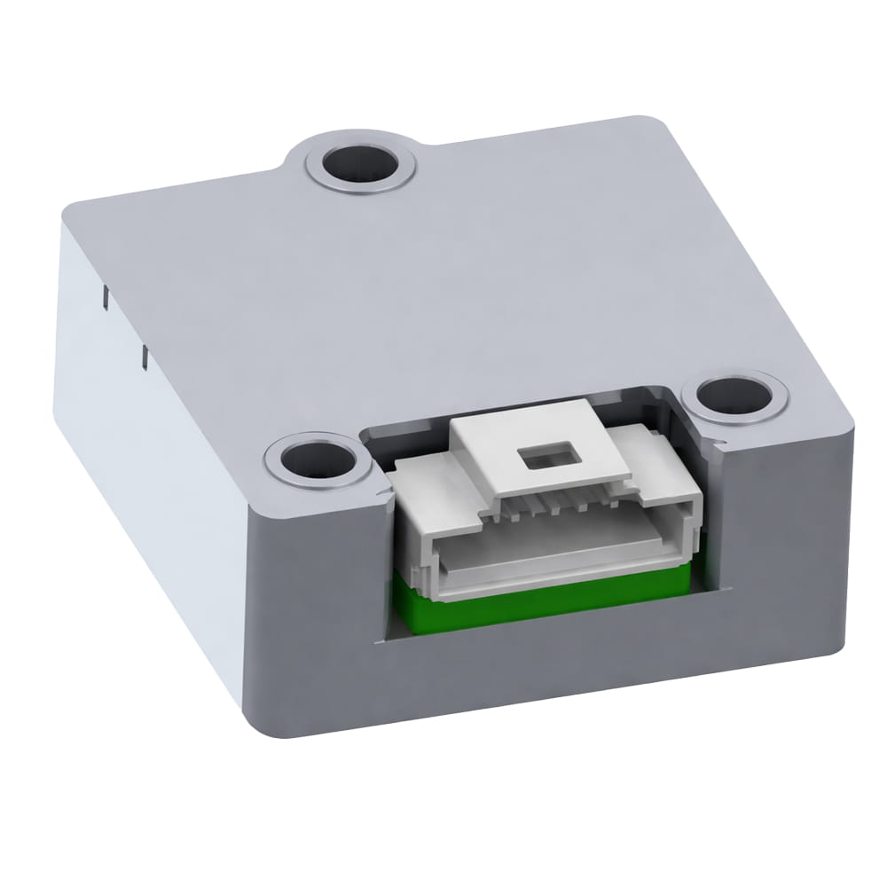
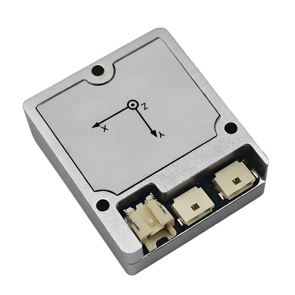
Waterproof Mems Imu U3700 High Accuracy Inertial Sensor with Canopen Modbus Protocols
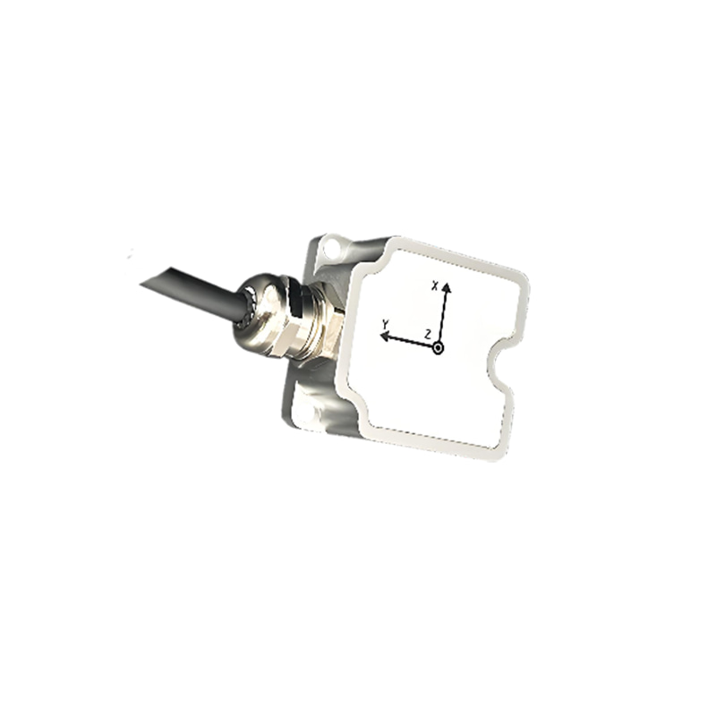
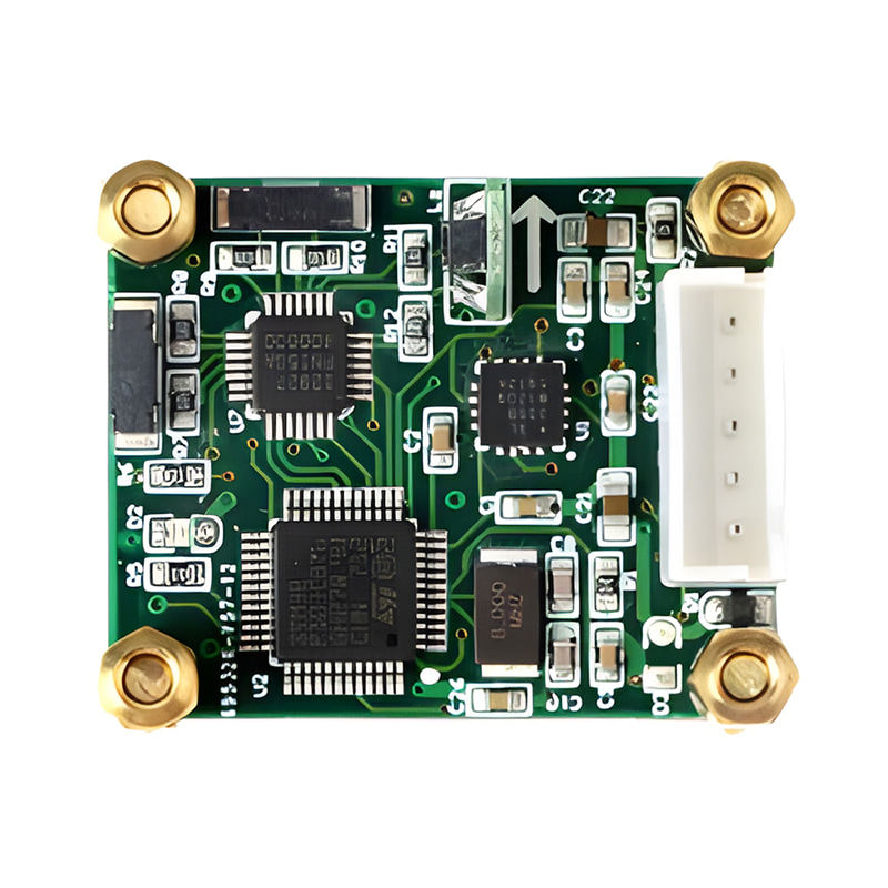
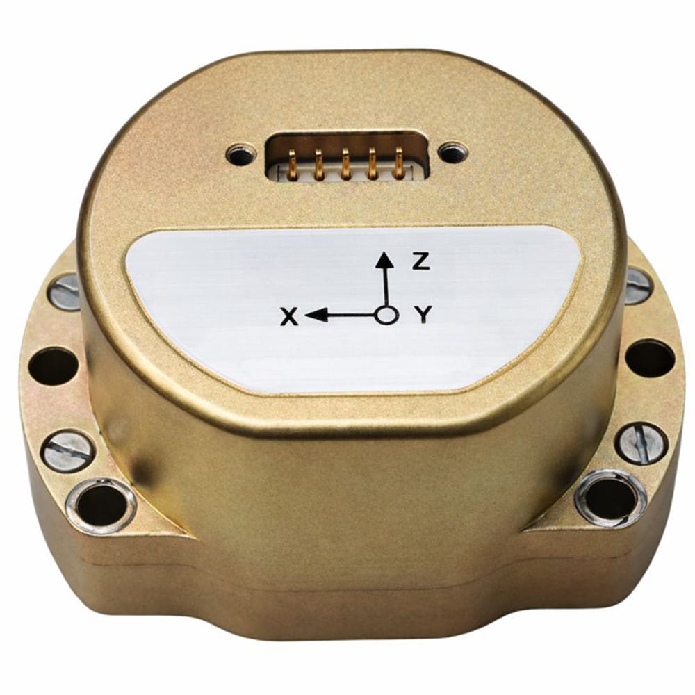
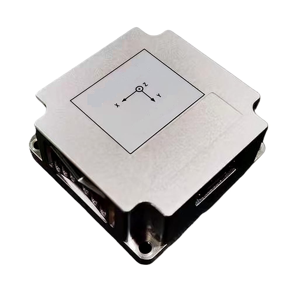
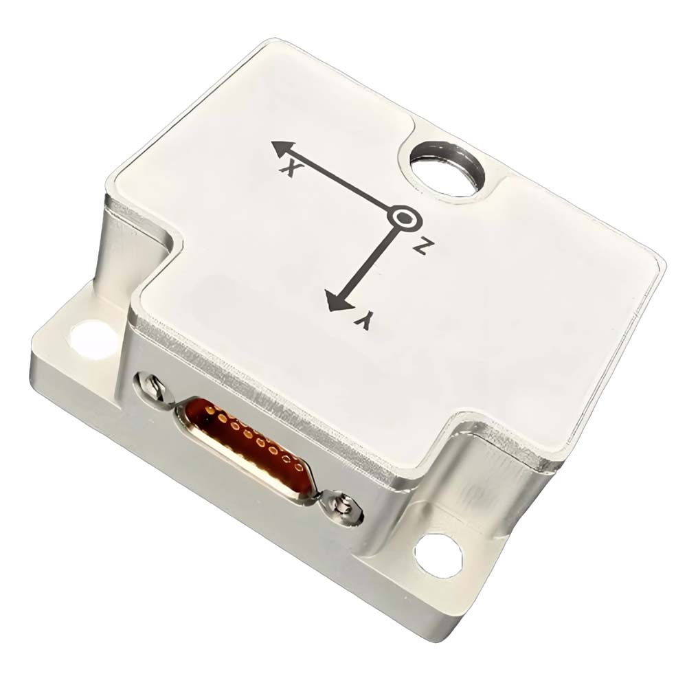
The U3700 series is an IMU/VRU/AHRS sensor composed of an array MEMS-IMU and a magnetometer. It is equipped with self-developed adaptive extended Kalman filtering, IMU noise dynamic analysis algorithm, and carrier motion state analysis algorithm, which can meet the accuracy of attitude angle under high dynamic conditions and reduce heading angle drift.
Every sensor undergoes fine compensation including temperature, zero bias, scaling factor, and cross axis before leaving the factory.
The U3700 series sensors transmit data through various interfaces such as UART (RS-232/TTL), RS-485, CAN, and have rich user configurations. The U3700 series can synchronize with the system through external triggering, and also align with external systems such as radar and camera time through synchronous output function. Multi-functional upper computer (GUI) can help quickly evaluate products, including but not limited to module configuration, data display, firmware upgrade, data recording, etc.
Part No, :
U3700Order(MOQ) :
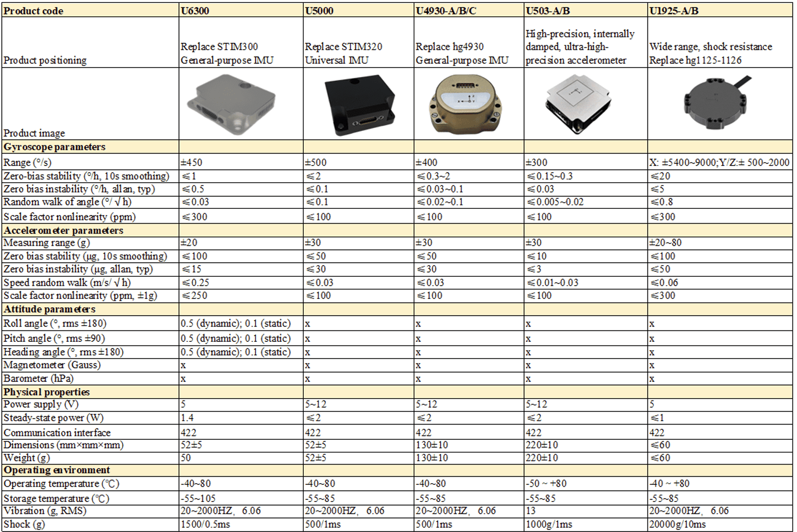
1Product Series and Parameters
| Attitude Precision | U3700-A | U3700-B | U3700-C | U3700-D | U3700-E | U3700-F | U3700-G | Unit |
| Pitch (±90°) /Roll (±180°) (static) | 0.15(nom), 0.2(max) | ° | ||||||
| Pitch (±90°) /Roll (±180°) (dynamic) | 0.15(nom) 0.3(max) | 0.15(nom) 0.2(max) |
° | |||||
| Yaw (±180°) static drift 2hrs (6DOF) ① | 0.15(nom), 0.2(max) | ° | ||||||
| Yaw (±180°) dynamic drift (6DOF) ② | 9 | 5 | ° | |||||
| Magnetic assist (AHRS)③ | 2(nom), 3(max) | ° | ||||||
| Yaw rotation error (6DOF) (rotation under 100°/s)④ | <0.8(nom) 3(max) |
<0.8(nom) 1(max) |
<0.8(nom) 1.3(max) |
° | ||||
| Note: ① Module horizontally stationary for 2 hours. ② The module was measured after 1 hour of movement on an indoor robot, 1σ ③ After geomagnetic calibration, the product needs to be configured in AHRS mode when there is no magnetic field interference in the surrounding area. ④ The turntable rotates continuously for 10 turns, and the heading angle accumulates error. |
||||||||
| Gyroscope | U3700-A | U3700-B | U3700-C | U3700-D | U3700-E | U3700-F | U3700-G | Unit |
| Measurement range | ±2000 | ±4000 | °/s | |||||
| Resolution | 16 | 20 | bit | |||||
| Scale factor(100°/s)① | <500(nom) 600(max) |
<200(nom) 350(max) |
<100(nom) 200(max) |
ppm | ||||
| Nonlinearity② | ±0.05 | %Fs | ||||||
| Noise density③ | 0.015 | 0.008 | 0.006 | 0.0025 | 0.0015 | °/s/√Hz | ||
| 3dB Bandwidth | 90(nom), 200(max) | 90(nom), 400(max) | Hz | |||||
| Zero speed output④ | ±0.1 | °/s | ||||||
| Sampling Rate | 1000 | Hz | ||||||
| Zero bias instability (Allan, 1σ) | 3 | 1.6 | 1.2 | 1.7 | 1 | °/h | ||
| Zero bias stability (10s, 1σ) | 10 | 5 | 4 | 2.3 | °/h | |||
| Zero bias repeatability (1σ) | 15 | 12 | 8 | 3.7 | 1.8 | °/h | ||
| Angle random walk (Allan 1σ) | 0.42 | 0.25 | 0.18 | 0.15 | 0.05 | °/√h | ||
| Full temperature zero bias-40-85℃⑤ | 0.07(nom), 0.2(max) | °/s | ||||||
| Accelerometer sensitivity (All 3 axis) | 0.1 | 0.05 | °/s/g | |||||
| Notes: ①: Rotate the turntable 10 times in both directions and take the average measurement ②: Maximum deviation from the best fit line within the specified range ③: Test the sample mean ④: After the initial zero-bias calibration, the zero bias can be estimated in real-time in the algorithm engine. ⑤: The temperature rise slope measured by the temperature chamber turntable in the lab is less than 3℃/min. |
||||||||
| Accelerometer | U3700-A | U3700-B | U3700-C | U3700-D | U3700-E | U3700-F | U3700-G | Unit |
| Measurement range | ±12 | ±8(nom), ±32(max) | g | |||||
| Resolution | 16 | 20 | bit | |||||
| Initial bias drift | 5(max) | 2(nom), 5(max) | mg | |||||
| Nonlinearity | 0.5 | 0.01 | %Fs | |||||
| 3dB Bandwidth | 80(nom), 200(max) | 80(nom), 400(max) | Hz | |||||
| Sampling Rate | 1600 | 1000 | Hz | |||||
| Zero bias instability (Allan, 1σ) | 0.03 | 0.018 | 0.014 | 0.012 | 0.007 | mg | ||
| Zero bias stability (10s, 1σ) | 0.07 | 0.035 | 0.025 | 0.015 | 0.008 | mg | ||
| Zero bias repeatability (1σ) | 0.34 | 0.15 | 0.1 | 0.11 | 0.05 | mg | ||
| Angle random walk (Allan, 1σ) | 0.08 | 0.04 | 0.028 | 0.018 | 0.01 | m/s/√h | ||
| Full temperature zero bias-40-85℃ (1σ) | 2(nom), 3(max) | 2.5(nom), 5(max) | mg | |||||
| Magnetometer | U3700-A | U3700-B | U3700-C | U3700-D | U3700-E | U3700-F | U3700-G | Unit |
| Range | / | / | ±8 | ±8 | / | ±20 | / | Gauss |
| Resolution (Fs=2G) | / | / | 2 | 2 | / | 2 | / | mGuass |
| Sampling | / | / | 200 | 200 | / | 200 | / | Hz |
| Linearity (Best fitting straight line Fs=2G) | / | / | 0.1 | 0.1 | 0.2 | Fs% | ||
| Temperature sensor | U3700-A | U3700-B | U3700-C | U3700-D | U3700-E | U3700-F | U3700-G | Unit |
| Range | -40 ~ +85 | ℃ | ||||||
| Offset error | ±1 | K | ||||||
| Mechanical/Environment | U3700-A | U3700-B | U3700-C | U3700-D | U3700-E | U3700-F | U3700-G | Unit |
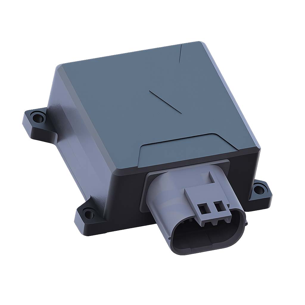
| Power supply | 4.8 ~ 48 (USB/UART(RS-232/TTL)) 7 ~ 48 (RS485/CAN) |
V | ||||||
| Power consumption | 300 | 400 | 600 | 400 | 600 | mW | ||
| Working temperature | -40 - 85 | ℃ | ||||||
| Starting time① | 2 | s | ||||||
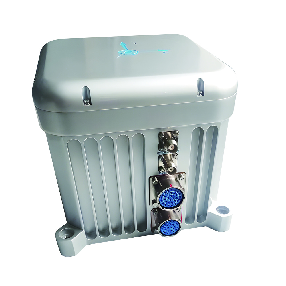
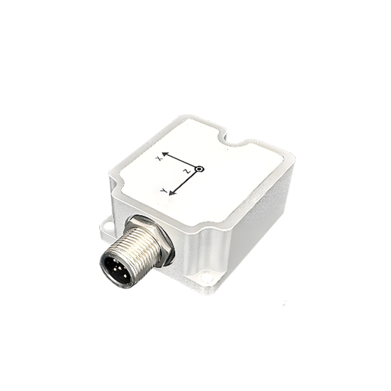
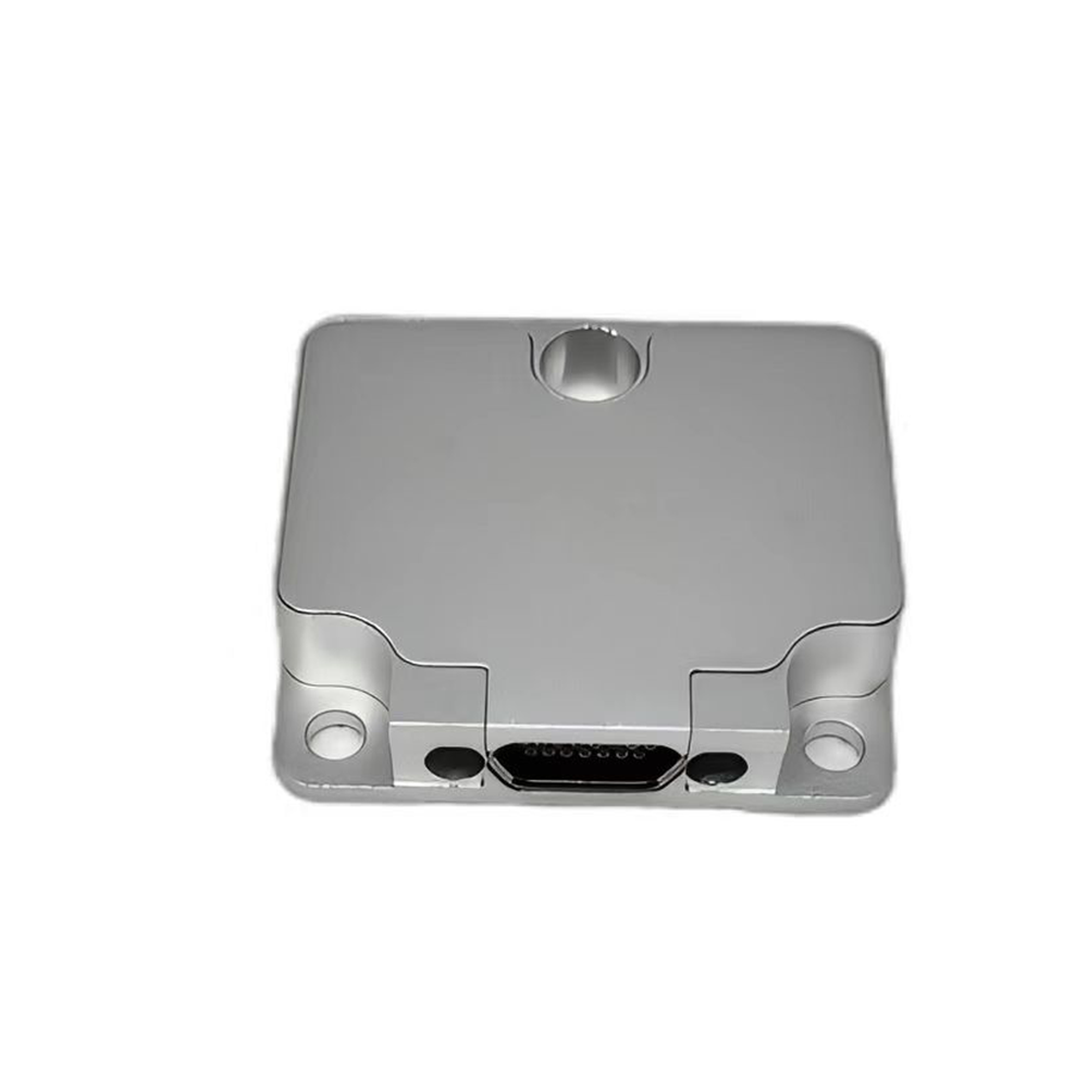
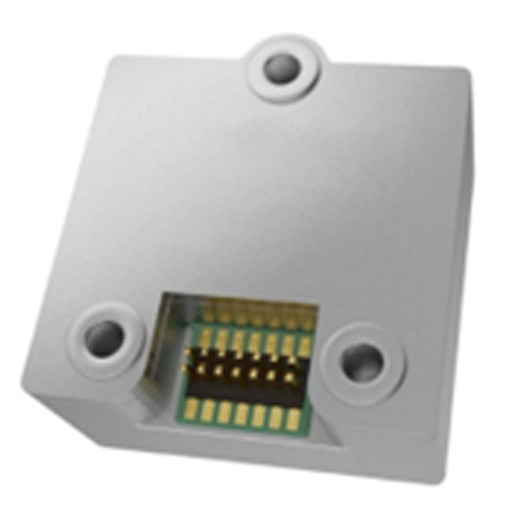
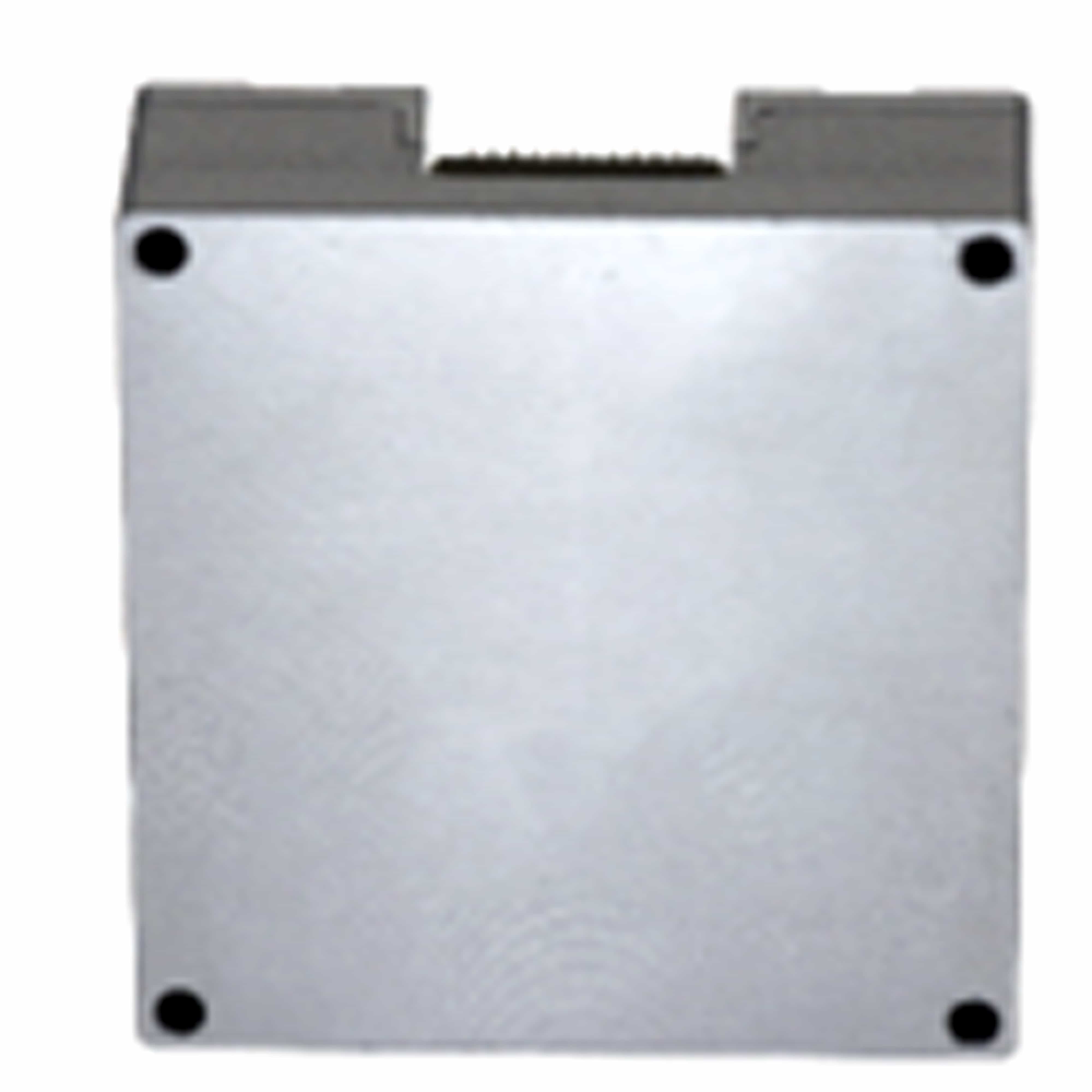
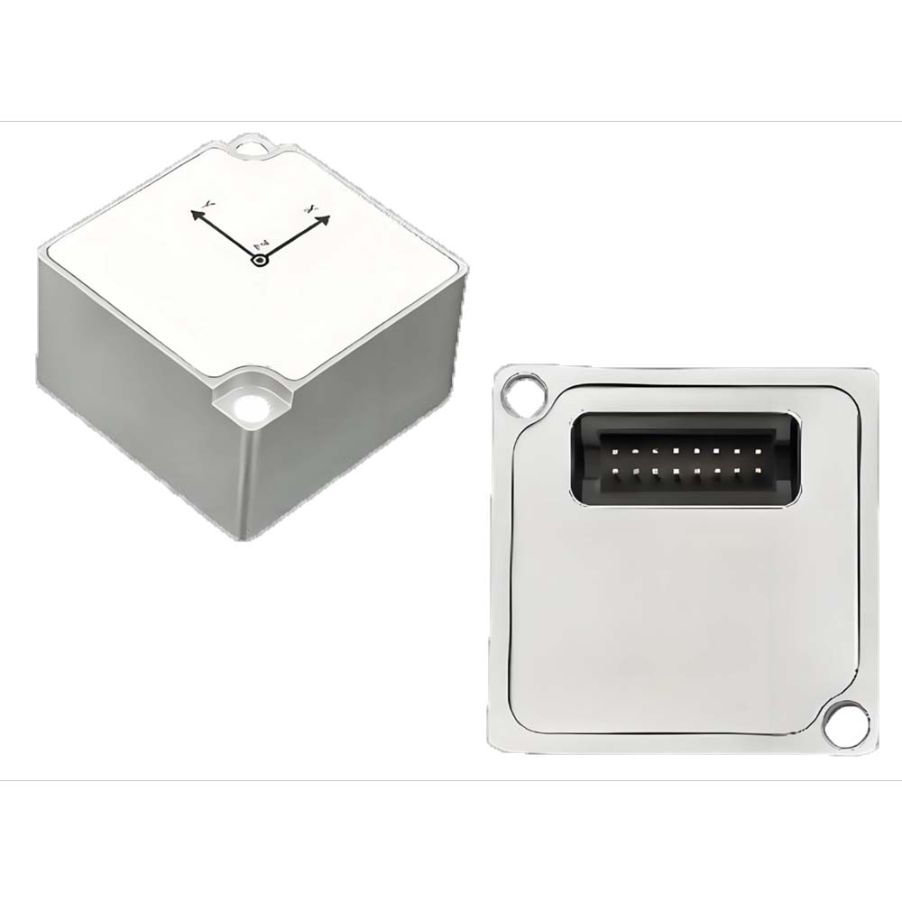
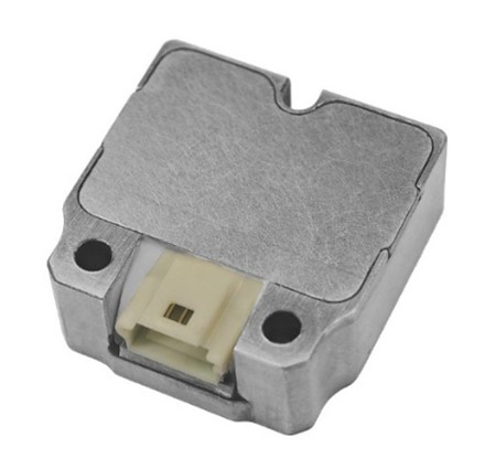
| Size | M12 connector interface: 58.5*40*20 PG connector interface: 40*36*16 |
mm | ||||||
| Weight | <75 | g | ||||||
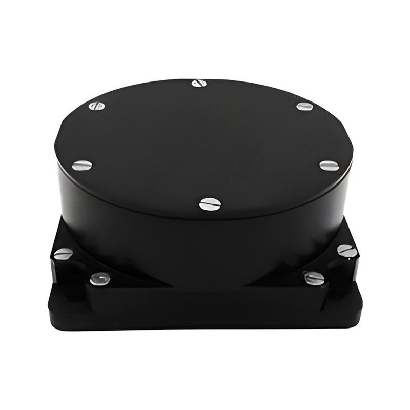
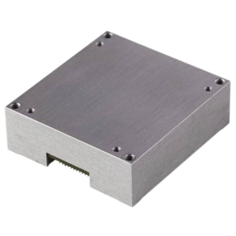
| Shell material and process | Aluminum alloy CNC | |||||||
| Assembling screws | M3 | |||||||
| Anti-Vibration | 1.0mm(10Hz-58Hz) &≤20g(58Hz-600Hz) | |||||||
| Shock (duration <1ms) | 2000 | g | ||||||
| Environment protection | RoHS Directive 2011/65/EU | |||||||
| EMC | CE | |||||||
| IP grade | IP68 Anti-water | |||||||
| Drop test | Free fall 3 times on a 75cm high experimental platform | |||||||
| Temperature shock | Raise the temperature from -40 to 85 ℃ within 1h, 5 times | |||||||
| Notes: ① Startup time refers to the time it takes for the system to shut down and output valid data. During this period, the module should be kept stationary |
||||||||
| Interface | Parameters | Condition | Min | Normal | Max | Unit |
| UART | Baud-rate① | 9600 | 115200 | 921600 | bps | |
| Starting bits | 1 | bit | ||||
| Data length | 8 | bits | ||||
| Stop bit | 1 | bit | ||||
| Checksum | None | bit | ||||
| Output framerate② | 0 | 100 | 1000 | Hz | ||
| Input impedance | RS-232 | 3 | 5 | 7 | kΩ | |
| Output impedance | 300 | 10M | Ω | |||
| CAN | Baud-rate③ | 125 | 500 | 1000 | kbps | |
| Output framerate④ | 5 | 100 | 200 | Hz | ||
| Input impedance⑤ | with 120 Ω resistor | 120 | Ω | |||
| without 120 Ω resistor | 19 | 30 | 52 | kΩ | ||
| RS485 | Baud-rate | Modbus | 921600 | 115200 | 115200 | bps |
| non-Modbus | 921600 | 115200 | 460800 | bps | ||
| Starting bits | 1 | bit | ||||
| Data length | 8 | bits | ||||
| Stop bit | 1 | bit | ||||
| Checksum | None | bit | ||||
| Output Frame Rate | Modbus | 0 | 10 | 50 | Hz | |
| non-Modbus | 0 | 100 | 250 | Hz | ||
| Input impedance⑤ | with 120 Ω resistor | 120 | Ω | |||
| without 120 Ω resistor | 48 | kΩ | ||||
| Trigger Pin | Logic Voltage⑥ | High | 2 | V | ||
| Low | 0.6 | V | ||||
| Delay⑥ | From trigger to data transmission | 800 | us | |||
| Notes: ① If modifications are required, please refer to the instruction and programming manual. ② The sensor supports data output at 1, 5, 10, 50, 200, 250, 500, and 1000 Hz. ③ If modifications are required, please refer to the instruction and programming manual. ④ The sensor supports 5, 10, 50, 100, and 200 Hz data output. ⑤ By default, there is no 120 Ω resistor connected ⑥ Please refer to the synchronization function chapter and instruction and programming manual for triggering timing and configuration. |
||||||
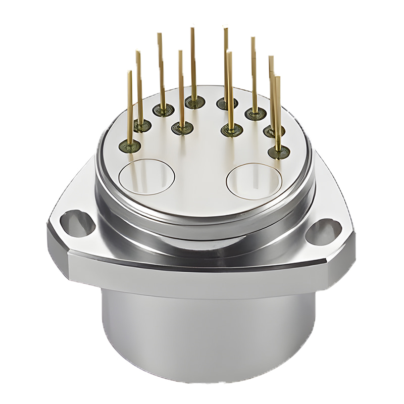
Production process
More similar products
Product dimension

Application Scenarios


FAQ

Xml Privacy Policy Blog Sitemap
copyright @ Micro-Magic Inc All Rights Reserved.
 Network Supported


 English