




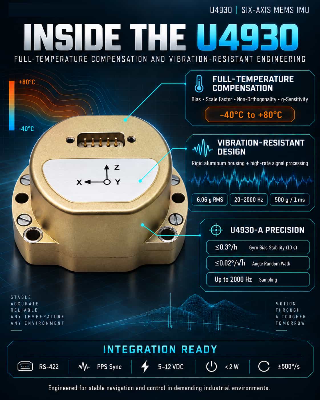
As industrial drones, autonomous driving systems, and high-precision navigation systems increasingly demand compact size, high performance, and low cost, MEMS Inertial Measurement Units (IMUs) are steadily advancing toward tactical-grade—and even navigation-grade—performance. The U4930 series of six-axis MEMS IMUs from Micro-Magic delivers a highly competitive solution, featuring robust full-temperature compensation technology, superior vibration resistance, and compatibility with leading international products (such as the HG4930). Core Technology: Full-Temperature Compensation and System Calibration One of the most critical sources of error in MEMS inertial devices is the drift in bias and scale factor caused by temperature fluctuations. Without effective compensation, even minor temperature changes can lead to massive errors in navigation calculations—a classic case of "a miss is as good as a mile." The U4930’s standout feature is its sophisticated compensation algorithm covering the entire operating temperature range (-40°C to +80°C). The system performs comprehensive temperature-based compensation for the bias, scale factor, non-orthogonality errors, and acceleration-dependent terms of both the gyroscope and accelerometer. This goes beyond simple linear correction; it relies on a complex error model established through extensive testing in environmental chambers. Consequently, the U4930-A model achieves a full-temperature bias stability of ≤0.3°/h (10s smoothing) and an angular random walk of ≤0.02°/√h. These specifications enable the system to maintain exceptional attitude accuracy during short periods without external aids (such as GNSS)—a capability that is crucial for navigation in tunnels, underground environments, or underwater. Mechanical Robustness: Vibration and Shock Resistance Harsh mechanical environments—characterized by high dynamics or vehicle/airborne mounting—pose another major challenge for MEMS IMUs. Intense vibration can introduce spurious angular velocity through mechanical coupling, causing attitude calculation errors to diverge. The U4930 addresses this with a robust structural design. Encased in a lightweight, high-strength aluminum alloy housing, the unit withstands random vibration of 6.06g (RMS) across the 20–2000 Hz range and shocks of 500g/1ms. Coupled with high-speed sampling (up to 2000 Hz) and synchronous processing capabilities, the U4930 leverages high-bandwidth data to effectively filter out vibration noise in the time domain, ensuring the output of stable, accurate motion data even amidst the intense shaking of rotor-wing drones or the jolting of vehicles. Strategic Positioning: A Seamless Drop-in Replacement for the HG4930 The U4930’s most ingenious feature is its strategic market positioning: it is fully compatible with Honeywell’s classic HG4930 IMU. This compatibility extends beyond physical dimensions and M4 screw mounting to include the RS422 differential interface and PPS synchronization signal definitions. Users can upgrade directly without modifying existing carrier boards or power architectures (supporting 5–12V input and <2W power consumption), gaining a wider gyroscope measurement range (±500°/s vs. ±400°/s) and superior noise performance. In summary, the U4930 is far more than a mere assembly of components. It eliminates temperature drift through system-level full-temperature compensation, resists vibration interference via a high-rigidity structure and high-speed sampling, and lowers the barrier to adoption through seamless hardware compatibility. For navigation and control systems demanding high reliability, this robust technical design and implementation embody the product's core value.
Read More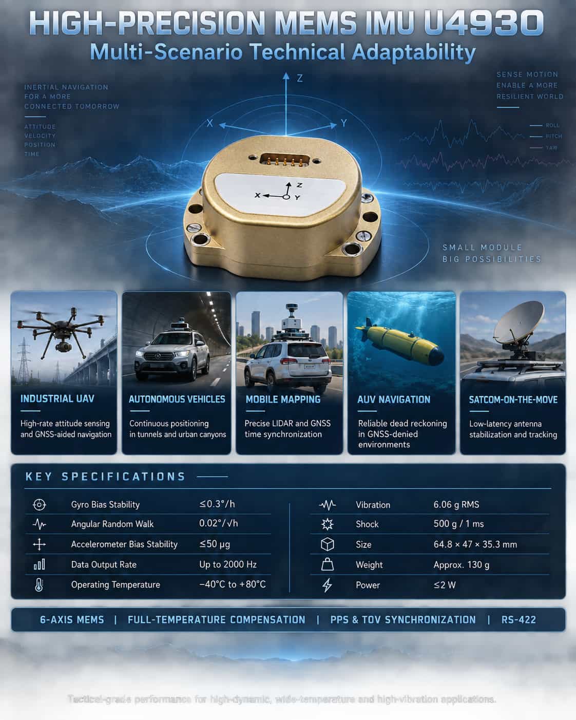
High-precision Inertial Measurement Units (IMUs) are core sensors for attitude sensing and autonomous navigation in moving platforms. In complex application scenarios—such as industrial drones, autonomous driving, mobile mapping, and underwater navigation—systems impose rigorous requirements regarding IMU accuracy, dynamic response, environmental resilience, and data synchronization capabilities. The U4930 series six-axis MEMS inertial measurement module from Micro-Magic Inc. offers a mature and reliable inertial sensing solution for these applications, featuring tactical-grade inertial specifications, precise full-temperature compensation, high-bandwidth output, and a compact, lightweight design. **Key Technical Features of the U4930** The U4930 integrates a high-performance three-axis MEMS gyroscope and a three-axis MEMS accelerometer. It features internal calibration and compensation across the full operating temperature range (-40°C to +80°C) for bias, scale factor, non-orthogonality errors, and acceleration-sensitive terms. The gyroscope offers a measurement range of ±400°/s to ±500°/s (depending on the model), with bias stability (10s smoothing) better than 0.3°/h and angular random walk as low as 0.02°/√h. The accelerometer features a ±30g range, bias stability better than 50μg, and velocity random walk ≤0.03 m/s/√h. The module measures just 64.8 × 47 × 35.3 mm and weighs approximately 130g, with a steady-state power consumption of ≤2W. It supports data output rates up to 2000Hz and offers robust performance, including 6.06g RMS vibration resistance and 500g/1ms shock resistance. These specifications demonstrate that the U4930 achieves tactical-grade MEMS IMU standards, capable of maintaining measurement accuracy under harsh conditions—such as high dynamics, wide temperature ranges, and intense vibration—thereby laying the foundation for its deployment across diverse application scenarios. Technical Adaptation Analysis for Typical Application Scenarios (1) Industrial Drones: High-Dynamic Attitude Reference and Dead Reckoning Industrial drones require real-time, high-update-rate attitude data (roll, pitch, and yaw) for stable flight control and autonomous navigation. The U4930’s 2000 Hz data output rate ensures precise capture of the airframe's transient angular motion, while its angular random walk (as low as 0.02°/√h) effectively suppresses the rate of attitude integration drift. The module supports time synchronization with GNSS receivers (via PPS input and GPRMC message parsing), enabling loosely or tightly coupled integrated navigation; it maintains trajectory continuity through pure inertial dead reckoning during brief GNSS signal outages—a capability critical for tasks such as power line inspection and long-endurance surveying. (2) Autonomous Vehicles: Continuous Positioning in Complex Operating Conditions For autonomous vehicles operating in environments where GNSS signals are obstructed—such as urban canyons, tunnels, and underground parking garages—the IMU becomes the core component for dead reckoning. The U4930’s bias stability (0.3°/h) and low-noise characteristics ensure that positional drift remains within acceptable limits over periods of tens of seconds. Its full-temperature-range compensation mechanism guarantees consistent performance despite temperature fluctuations in the engine compartment (-40°C to 80°C), while its 6.06g vibration resistance effectively mitigates measurement disturbances caused by road bumps and engine vibrations. A tiered precision lineup (Models A, B, and C) allows systems ranging from L2+ to L4 autonomy—and with varying budget constraints—to access inertial performance tailored to their specific needs. (3) Mobile Mapping and Track Inspection: High-Precision Spatiotemporal Reference Synchronization Vehicle-mounted or airborne LiDAR systems require IMUs to provide high-precision attitude and position references to ensure the accuracy of 3D point cloud registration. The U4930’s low angular random walk (≤0.02°/√h) directly translates to reduced point cloud drift, a factor that is particularly crucial for long-distance data acquisition missions. Additionally, its TOV differential synchronous pulse output and PPS input capabilities enable strict synchronization between IMU sampling moments and GNSS one-pulse-per-second (PPS) signals, providing precise trigger signals for point cloud timestamping. In railway track inspection, the module can be integrated with an odometer and GNSS to form a combined measurement system capable of detecting track irregularities with millimeter-level precision. (4) Autonomous Underwater Vehicles (AUV): Long-duration dead reckoning in GNSS-denied environments Underwater environments preclude GNSS signal reception, forcing AUVs to rely entirely on their internal inertial systems for long-duration pose estimation. The U4930’s tactical-grade gyro bias stability (as low as 0.3°/h) and low angular random walk effectively suppress the accumulation of attitude errors over time, thereby extending the vehicle's effective underwater operational duration. Its aluminum alloy structural design, shock resistance (500g), and wide storage temperature range (-55°C to 85°C) ensure it can withstand the mechanical stresses associated with the assembly and transport of deep-sea equipment. (5) Satcom-on-the-Move (SOTM): Closed-loop stable antenna tracking In vehicle-, ship-, or airborne SOTM systems, the IMU must provide instantaneous carrier attitude changes with low latency to drive servo mechanisms for antenna pointing compensation. The U4930’s bandwidth of ≥200 Hz ensures rapid attitude signal tracking, while its RS422 differential interface offers robust interference resistance, making it suitable for communication platforms operating in complex electromagnetic environments. When paired with external PPS synchronization, it provides a precise time reference for the antenna pointing control loop, ensuring communication link stability even during sharp turns or disturbances caused by wind and waves. Expanded application scenarios through environmental adaptability The U4930 operates within a temperature range of -40°C to 80°C and supports storage temperatures from -55°C to 85°C, ensuring reliable startup and operation in extreme cold, intense heat, and high-humidity conditions. Its vibration and shock resistance make it suitable not only for vehicle- and airborne applications but also for deployment on small vessels, unmanned ground vehicles (UGVs), and in certain industrial robotics scenarios. Furthermore, the module features a startup time of ≤2 seconds and supports in-field software upgrades, facilitating on-site maintenance and functional updates. In summary, the U4930 series MEMS IMU—characterized by tactical-grade inertial performance, precise compensation across the full temperature range, high-speed data output, and robust environmental adaptability—is ideally suited for demanding applications such as industrial drones, autonomous driving, mobile mapping, underwater navigation, and SATCOM-on-the-move. Its tiered accuracy options offer users flexibility in balancing cost and performance. As inertial navigation systems evolve toward miniaturization, low power consumption, and high reliability, the U4930 leverages its comprehensive technical specifications to provide a solid hardware foundation for attitude sensing and autonomous positioning across a wide range of mobile platforms.
Read More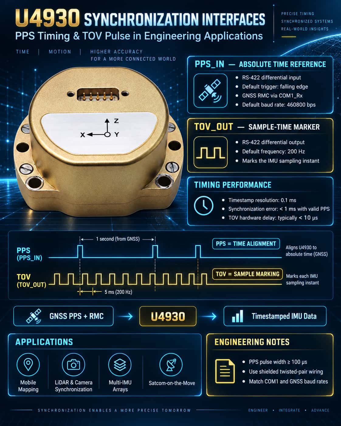
In integrated navigation systems, time synchronization is a critical factor determining data fusion accuracy. The U4930 MEMS IMU offers comprehensive synchronization interfaces—PPS input and TOV output—designed to handle the introduction of an external time reference and the calibration of internal sampling moments, respectively. Proper utilization of these interfaces significantly enhances system time-alignment accuracy, making the unit ideal for applications demanding strict clock consistency, such as UAV swarms, mobile mapping, and SATCOM-on-the-move (SOTM). PPS_IN: The "Heartbeat" of the External Time Reference PPS (Pulse Per Second) is a signal provided by Global Navigation Satellite Systems (GNSS); its rising or falling edge corresponds to the exact start of a second, typically with nanosecond-level precision. The U4930 receives the external PPS signal (RS-422 level) via the PPS_IN± differential interface while simultaneously receiving GPRMC/GNRMC/GBRMC sentences (default baud rate: 460800 bps) from the same GNSS source via the COM1_Rx± interface. Internally, the system uses the PPS falling edge as the synchronization trigger (default configuration). Upon detecting a valid pulse, the IMU parses the UTC time from the most recently received RMC sentence on COM1 and aligns it with an internal counter, thereby generating a high-precision internal timestamp (Timestamp field, 0.1 ms resolution). This mechanism ensures that every data frame output by the IMU carries an absolute time tag consistent with the GNSS system, providing the necessary time reference for subsequent loose or tight coupling with GNSS position and velocity data. Engineering Application Recommendations: · Ensure the PPS signal levels comply with the RS-422 differential standard to avoid latency introduced by single-ended conversion; · A PPS pulse width of ≥100 μs is recommended; the steepness of the falling edge directly impacts synchronization accuracy; · If the GNSS receiver outputs only a single-ended PPS signal, a differential converter is required to connect to the PPS_IN± interface; · The system supports configuration for either PPS rising-edge or falling-edge triggering; users can adjust this setting via the host computer based on the specific characteristics of the GNSS module. TOV_OUT: "Timestamp Marker" for Sampling Instants TOV (Time of Validity) is a differential synchronization pulse signal (TOV±) actively output by the U4930; its frequency matches the IMU's internal sampling frequency (default: 200 Hz). The rising or falling edge of this pulse precisely corresponds to the start of the IMU data sampling interval, and its differential signal levels comply with the RS-422 standard. The core value of TOV lies in enabling precise time-offset calculations between IMU sampling instants and external sensor acquisition times. When the U4930 operates alongside external devices (such as cameras, LiDAR, or scanners), these devices can capture the TOV pulse and record their local timestamps. By correlating this with the internal timestamp found in the IMU data frame, users can calculate the exact time lag and apply interpolation compensation during data post-processing or real-time sensor fusion. Typical Application Scenarios: · Mobile Mapping Systems: Synchronizing the IMU with a laser scanner; TOV is used to calibrate the attitude timestamp corresponding to specific scan lines. · UAV Visual Navigation: TOV triggers camera exposure, achieving millisecond-level alignment between images and attitude data. · Multi-IMU Arrays: Synchronous acquisition of TOV signals from multiple U4930 units to achieve clock synchronization across multiple nodes. Operational Mechanism and Engineering Considerations (1) Relationship between PPS and TOV: PPS is used for "time synchronization," while TOV is used for "marking." Although they operate independently, using them in tandem enables precise tracing of sampling instants against a global time reference. (2) Baud Rate Consistency: The default baud rate for GNSS input on COM1_Rx matches the IMU output baud rate (both are 460800 bps). If the output baud rate is changed, the GNSS module's baud rate must be updated accordingly; otherwise, RMC sentences cannot be parsed. (3) Data Frame Timestamp Parsing: The Timestamp field in the protocol (bytes 35–38; conversion factor: 0.1 ms) represents an internal counter value. When PPS synchronization is active, this value is periodically corrected, resulting in an error of less than 1 ms. If no PPS signal is connected, the value relies on the internal crystal oscillator for timing, leading to cumulative drift. (4) TOV Latency Compensation: The TOV output entails an inherent hardware latency (typically <10 μs). If the system requires sub-microsecond synchronization, it is recommended to calibrate this latency value prior to factory shipment or to subtract the fixed offset during post-processing. (5) ESD Protection and Wiring Reliability: Differential signal lines should utilize shielded twisted-pair cables and avoid running parallel to power lines to minimize common-mode interference. In summary, the U4930’s PPS timing interface integrates the MEMS IMU into the GNSS absolute time framework, transforming it from a standalone "blind-reckoning" unit into a synchronization node within an integrated navigation system. Meanwhile, the TOV pulse provides a physical marker for sampling instants, facilitating timestamp alignment across multiple sensors. Together, these features enable the U4930 to achieve time synchronization accuracy superior to 1 ms in applications such as UAVs, autonomous driving, surveying and mapping, and COTM (Communications on the Move), thereby laying a solid foundation for highly reliable attitude determination and multi-source data fusion.
Read More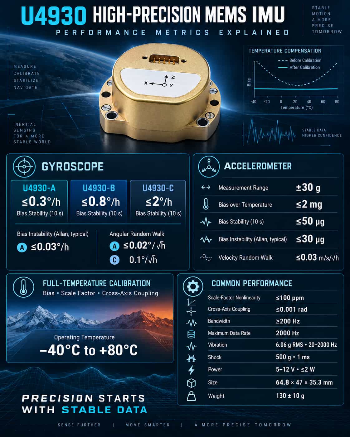
As the core sensing unit for inertial navigation and control, the performance parameters of an IMU directly determine the upper limits of accuracy for system attitude determination and navigation positioning. With distinct model classifications and full-temperature-range calibration capabilities, the U4930 series of MEMS IMUs offers performance options tailored to diverse application scenarios. This article provides a systematic analysis of the series' key performance indicators. 1. Gyroscope Performance: Precision Determines Attitude Stability Gyroscope bias stability is a key metric for measuring long-term angular drift. The U4930-A model achieves ≤0.3°/h (10s), while the B model offers ≤0.8°/h and the C model ≤2°/h. For vessels or drones requiring sustained heading accuracy over long periods, the A model clearly holds the advantage; conversely, for cost-sensitive commercial vehicles where periodic recalibration is acceptable, the B or C models are sufficient. Bias instability (characterized by Allan variance) reflects the ultimate noise floor. The A model’s typical value of ≤0.03°/h indicates minimal angular drift under ideal static conditions, making it suitable for high-precision surveying and track inspection. Angle Random Walk (ARW) influences the accumulation of angular errors in dynamic environments. The A model’s ARW of ≤0.02°/√h is far superior to the C model’s 0.1°/√h, enabling better performance in flight control scenarios involving intense vibration or rapid maneuvering. Notably, all three models feature scale factor nonlinearity of ≤100 ppm, cross-axis coupling of ≤0.001 rad, and a bandwidth of ≥200 Hz. These specifications ensure rapid response and minimal inter-axis interference, meeting the requirements of most real-time control applications. 2. Accelerometer Performance: Balancing Stability and Sensitivity The entire U4930 series features an accelerometer measurement range of ±30g, covering the typical maneuvering ranges of vehicles, vessels, and drones. Key specifications include a full-temperature bias of ≤2 mg, bias stability of ≤50 μg (10s), bias instability of ≤30 μg (Allan typical value), and velocity random walk of ≤0.03 m/s/√h; these metrics place the series in the high-performance tier for MEMS-based sensors. For inertial navigation systems, accelerometer bias stability directly impacts the cumulative error in velocity and position calculations. A stability of 50 μg ensures that velocity errors remain at a low magnitude during one hour of pure inertial dead reckoning, making it suitable for navigation during brief GNSS signal outages. 3. Environmental Adaptability and Physical Characteristics The entire U4930 series supports an operating temperature range of -40°C to +80°C and undergoes calibration across the full temperature range for bias, scale factor, and cross-coupling compensation. It demonstrates excellent mechanical robustness, with vibration tolerance of 6.06g (RMS, 20–2000 Hz) and shock tolerance of 500g/1ms. Key specifications include a supply voltage of 5–12V, steady-state power consumption ≤2W, startup time ≤2s, a maximum data rate of 2000 Hz, dimensions of 64.8 × 47 × 35.3 mm, and a weight of 130 ± 10 g, striking a balance between miniaturization and low power consumption. 4. Selection Recommendations and Summary · U4930-A: Suitable for applications requiring extremely high performance regarding bias and random walk, such as mobile mapping, high-precision underwater navigation, and SATCOM-on-the-move (SOTM). · U4930-B: Suitable for medium-precision applications, such as UAV attitude reference, track inspection, and shipborne attitude measurement. · U4930-C: Suitable for cost-sensitive applications that tolerate higher drift, such as flight control and reference IMUs for commercial vehicles. Overall, the U4930 series maximizes the potential of MEMS technology through full-temperature calibration and a modular design. When selecting a model, users should prioritize whether the gyroscope bias stability and angular random walk meet the system's long-term navigation accuracy requirements, while also evaluating bandwidth and shock resistance against environmental vibration conditions. Properly matching specifications with requirements ensures an optimal balance between performance and cost.
Read More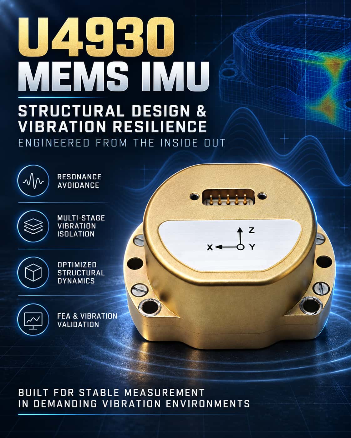
MEMS Inertial Measurement Units (MEMS IMUs) are widely used in fields such as navigation and attitude control; however, vibration environments can significantly degrade their measurement accuracy. Research indicates that external vibrations can cause severe output deviations in MEMS gyroscopes and may even lead to structural fatigue or fracture. Consequently, employing rational structural design and vibration-resistance optimization at the system level is crucial for enhancing the environmental adaptability of MEMS IMUs. **Vibration Interference Mechanisms and Design Objectives** The fundamental reason for the vibration sensitivity of MEMS IMUs lies in their operating principles. Taking the gyroscope as an example, its operation relies on the coupling between drive and sense modes; if external vibrations couple into these modes, they directly translate into output errors. Furthermore, structural resonance induced by vibration amplifies this effect. Therefore, structural design pursues two core objectives: first, avoiding resonance by using modal analysis to ensure the structure's natural frequencies remain well away from the frequency bands where vibration energy is concentrated; and second, isolating vibration by incorporating vibration-isolation elements along the transmission path to attenuate the vibration energy reaching sensitive components. **Key Structural Design Strategies** Current structural design approaches primarily follow two technical paths: First, system-level vibration isolation structures. Vibration isolation systems are created by embedding isolators (such as rubber pads or metal springs) between the IMU and the host platform, or between the internal core and the outer housing. Research suggests that to meet the compact size requirements of MEMS IMUs, multi-stage isolation designs can be employed—such as arranging three levels of damping pads (housing–core–measurement assembly) and utilizing stiffness gradients to achieve staged attenuation. More advanced solutions utilize motion-decoupling mechanisms to design six-degree-of-freedom isolation systems, thereby suppressing vibration coupling effects caused by isolator asymmetry. In typical applications, the use of a two-stage lattice isolation structure combined with redundant, multi-sensor 3D mounting can reduce the root-mean-square (RMS) value of angular velocity output by more than 88% under flight vibration spectra. Second, optimization of sensitive structures. At the chip level, vibration resistance can be enhanced at the source by employing high-symmetry structural designs (such as eight-mass or ring structures) that utilize differential principles to cancel out common-mode vibration interference, or by using a single-mass tri-axial gyroscope design featuring a central anchor and symmetric flexure bearings. Design Verification and Performance Evaluation Finite element analysis (FEA) serves as the most critical verification tool in this field. Modal analysis allows for the calculation of natural frequencies to assess resonance risks, while frequency response and random vibration analyses predict acceleration responses under specific power spectral densities, providing a basis for design iteration. Experimental verification typically encompasses calibration and vibration testing. For instance, one optimized design—utilizing methods such as adding support beams and reducing fixed spans—more than doubled the vibration resistance of the IMU compared to the original design; another lightweight IMU demonstrated excellent vibration resistance alongside high precision during vibration testing. In summary, the vibration resistance of MEMS IMUs is a system-level issue that requires a structural dynamics perspective and the integrated application of techniques such as modal analysis, vibration isolation design, and optimization simulation. Adopting "avoiding resonance" and "efficient vibration isolation" as core design principles offers an effective pathway for developing highly reliable MEMS IMUs. Looking ahead, advancements in materials science and control algorithms will enable MEMS IMUs to maintain performance in increasingly extreme vibration environments, opening up broader application prospects.
Read More
1. Overview Inertial Measurement Units (IMUs) are core sensors in fields such as drones, robotics, autonomous driving, and precision surveying. For a long time, the market for high-end MEMS IMUs was dominated by a few overseas manufacturers. In recent years, however, various domestic products have successfully matched mainstream international models in terms of performance specifications, package dimensions, and interface protocols, offering end-users more diverse supply chain options. This article selects four sets of representative benchmark models—ADIS16488 vs. U16488, ADIS16495 vs. U16495, STIM300 vs. U6300, and HG4930 vs. U4930—and conducts a comprehensive side-by-side comparison of their parameters, covering aspects such as gyroscopes, accelerometers, physical characteristics, and environmental adaptability. 2. Overview of Key Parameter Comparisons 2.1. ADIS16488 vs. U16488 Model ADIS16488 (Imported) U16488 (Domestic) Type 10-axis (+ magnetometer + barometer) 10-axis (+ magnetometer + barometer) Package (mm) 47 × 44 × 14 47 × 44 × 14 (drop-in replacement) Gyro Range (°/s) ±450 ±500 Gyro Bias Instability (°/h) 5.1 0.8 Gyro Angular Random Walk (°/√h) 0.26 0.2 Accelerometer Range (g) ±18 ±16 Accelerometer Bias Instability (mg) 0.07 0.03 Accelerometer Velocity Random Walk (m/s/√h) 0.029 0.04 Interface SPI SPI/UART Operating Voltage 3V ~ 3.6V 3V ~ 3.6V Operating Temperature -40°C ~ 105°C -40°C ~ 80°C Benchmarking Conclusion: The U16488 is fully compatible with the ADIS16488 in terms of package dimensions, pin assignments, and SPI interface, enabling seamless drop-in replacement. Its gyro bias instability outperforms the imported model by an order of magnitude, significantly enhancing the long-term stability of attitude estimation. Although its maximum operating temperature is slightly lower, it is perfectly suitable for standard industrial and UAV applications, offering distinct advantages in overall cost-performance and supply stability. 2.2. ADIS16495 vs. U16495 Model ADIS16495 (Imported) U16495 (Domestic) Type 6-axis 6-axis Package (mm) 47 × 44 × 14 47 × 44 × 14 (Drop-in replacement) Gyro Range (°/s) ±450 ±500 Gyro Bias Instability (°/h) 0.8 – 3.3 0.3 Gyro Angular Random Walk (°/√h) 0.09 0.1 Accelerometer Range (g) ±8g ±20g (±40g optional) Accelerometer Bias Instability (mg) 0.05mg 0.01mg Accelerometer Velocity Random Walk (m/s/√h) 0.008 0.03 Interface SPI SPI/UART Operating Voltage 3V – 3.6V 3V ~ 3.6V Operating Temperature −40°C – 105°C -40°C ~ 80°C Benchmarking Conclusion: The U16495 is fully compatible with the ADIS16495 in terms of mechanical dimensions and electrical interfaces, allowing for direct replacement without hardware modifications. It features a gyro bias instability as low as 0.3°/h and an extended accelerometer measurement range (±20g, with an optional ±40g), making it suitable for high-dynamic applications. With overall performance matching or exceeding that of the original product, it serves as a reliable domestic alternative for high-end navigation and control systems. 2.3. STIM300 vs U6300 Model STIM300 (Imported) U6300 (Domestic) Type 9-axis (+ inclinometer) 9-axis (+ inclinometer) Dimensions/Weight 38.6×44.8×21.5mm /55g 38.6×44.8×10mm / 50g Power Consumption 1.5W 1.4W Gyroscope Range (°/s) ±400 ±450 Gyroscope Bias Instability (°/h) 0.3 - 0.5 0.1 - 0.5 Gyroscope Angular Random Walk (°/√h) 0.15 0.03 Accelerometer Range (g) ±10 ±20 Accelerometer Bias Instability (mg) 0.006 0.01 Accelerometer Velocity Random Walk (m/s/√h) 0.024 0.02 Interface RS422 RS422 Operating Voltage 5V 5V Operating Temperature −40°C ~ 85°C −40°C ~ 85°C Benchmarking Conclusion: While being thinner and lighter, the U6300 matches the STIM300 in RS422 interface and power supply specifications, ensuring easy replacement. Its angular random walk (0.03°/√h) is significantly superior to the imported product, and it exhibits lower angular measurement noise, making it particularly well-suited for high-precision pointing and stabilization control tasks. It offers a matching full-temperature operating range and comprehensive performance parity, with certain specifications actually surpassing the benchmark. 2.4. HG4930 vs U4930 Model HG4930 (Imported) U4930 (Domestic) Type Tactical-grade six-axis Tactical-grade 6-axis (A/B/C settings) Dimensions/Weight 65 x 51 x 35.5mm/140g
Read More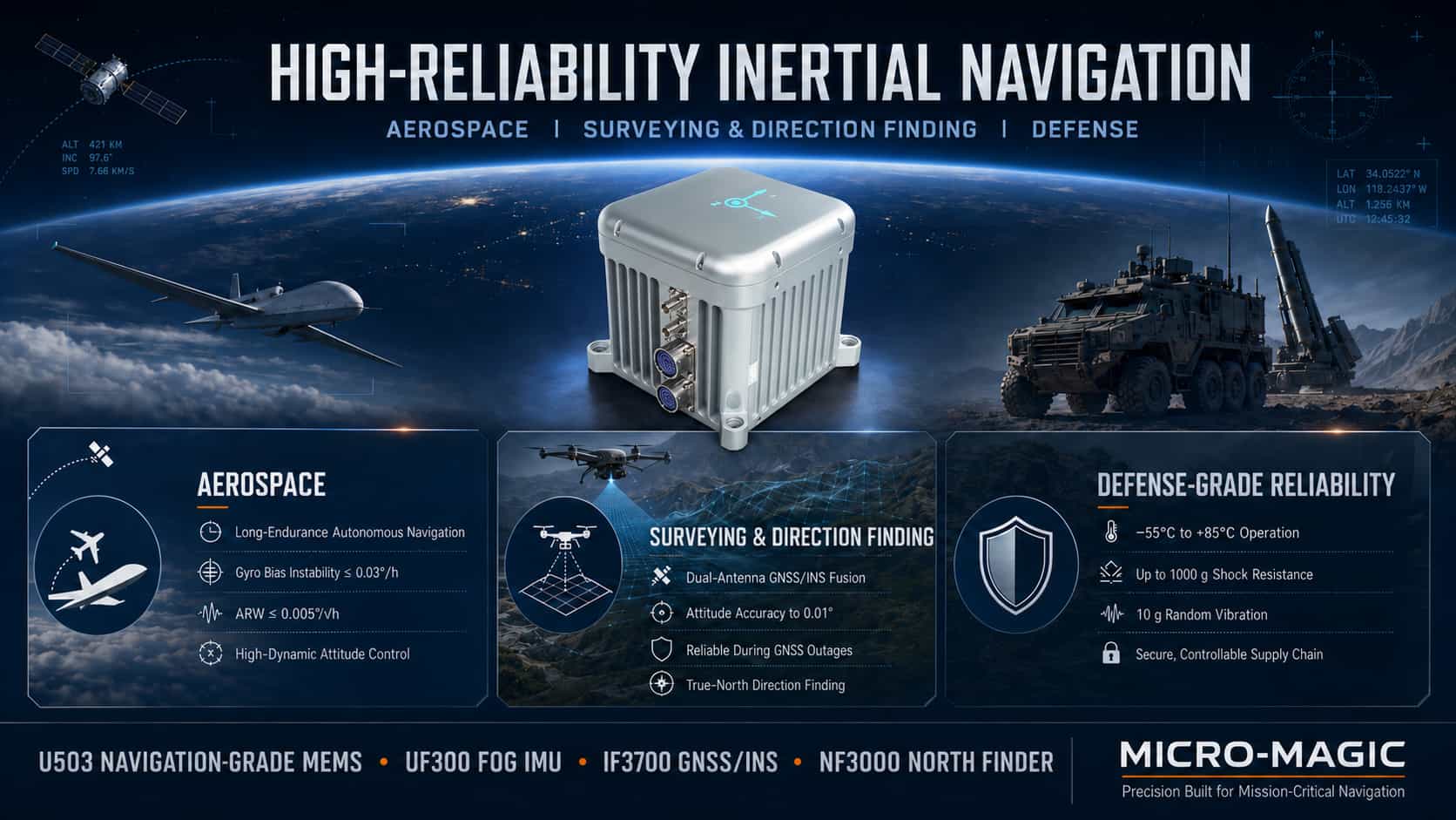
For inertial navigation systems, higher technical specifications are not necessarily better; rather, the goal is to strike an optimal balance among accuracy, size, weight, power consumption, cost, and reliability. The three major sectors—aerospace, surveying and orientation, and military equipment—have distinct technical priorities for inertial navigation products, leading to differentiated product technology roadmaps and selection criteria. The aerospace sector emphasizes high-precision attitude maintenance and long-term autonomous navigation capabilities. The surveying and orientation sector prioritizes high-precision attitude measurement and integrated navigation accuracy, with the deep fusion of inertial navigation and GNSS being critical. Military-grade applications impose the most stringent requirements regarding environmental adaptability, high-g load tolerance, and supply chain reliability. The following analysis examines the core technical specifications and typical product configurations for these three application scenarios. 1. Technical Analysis of Inertial Navigation Products in the Aerospace Sector Aerospace applications encompass a wide range of platforms, from satellites and hypersonic vehicles to tactical UAVs. Common technical requirements include high-precision attitude referencing, long-duration autonomous navigation, adaptability to high-dynamic environments, and the ability to operate across a wide temperature range. Core technical specifications center on attitude accuracy and autonomous navigation accuracy. A gyroscope bias instability of ≤0.03°/h serves as the baseline threshold for navigation-grade products, directly determining the heading drift rate; angular random walk of ≤0.005°/√h dictates short-term attitude noise levels; accelerometer bias instability of ≤10μg affects the accuracy of velocity and position dead reckoning; and scale factor stability of ≤50ppm ensures measurement linearity under high-dynamic conditions. Regarding technology roadmaps, satellite attitude control systems typically utilize fiber-optic gyro (FOG) or laser gyro IMUs (with bias instability of 0.002–0.01°/h), whereas tactical UAVs and missiles may employ high-precision MEMS IMUs (≤0.03°/h) to reduce size and cost. Taking Micro-Magic’s products as an example, the U503 series navigation-grade MEMS IMU features gyroscope bias instability of ≤0.03°/h, angular random walk of ≤0.005°/√h, and accelerometer bias instability of ≤3μg, effectively meeting the navigation requirements for lightweight UAVs and tactical missiles. The UF300 series FOG-based IMU delivers a gyro bias stability of 0.03°/h (10s smoothing) and an accelerometer bias stability of 3×10⁻⁵g (10s smoothing); a 4kHz raw data update rate ensures the capture of complete motion information during high-dynamic maneuvers. Regarding engineering implementation, a full-temperature compensation algorithm limits zero-bias variation across the entire operating temperature range to within 20% of the nominal value, while cross-axis coupling suppression of ≤0.001 rad ensures tri-axial orthogonality. Typical product configurations: Satellites and hypersonic vehicles utilize FOG-based IMUs (UF300) or laser gyro systems; large UAVs employ FOG-based IMUs (U-F3X90) or tactical-grade MEMS IMUs; tactical UAVs and missiles use navigation-grade MEMS IMUs (U503) or tactical-grade MEMS IMUs (U5000/U6300). 2. Technical Analysis of Inertial Navigation Products for Surveying, Mapping, and Orientation Applications in surveying, mapping, and orientation—such as high-precision map data acquisition, engineering surveying, marine mapping, and precision agriculture—present technical requirements that differ significantly from those in aerospace: high-precision attitude and heading directly impact the geometric accuracy of survey results; integrated navigation serves as the core operational mode, featuring deep fusion between inertial navigation and GNSS; dual-antenna assisted orientation compensates for the limited heading observability of single-antenna systems; and post-processing software can further enhance accuracy. Key performance indicators for inertial navigation systems in this sector center on integrated navigation attitude accuracy and the ability to maintain performance during short-term GNSS outages. Real-time attitude accuracy requirements are ≤0.01–0.05° for roll/pitch and ≤0.05–0.2° for heading, with post-processing capabilities improving these figures to ≤0.004–0.01° for roll/pitch and ≤0.01–0.05° for heading. Accelerometer bias stability of ≤10–30 μg ensures accuracy during short-term dead reckoning. Even after a 60-second GNSS outage, the system must maintain attitude and heading accuracy within ≤0.01°. Micro-Magic’s I3700 dual-antenna GNSS/INS integrated navigation system represents a standard configuration for surveying and orientation applications. The core technical value of the dual-antenna setup lies in its ability to determine heading: while single-antenna systems struggle to reliably measure heading when the platform is stationary or moving at low speeds, dual-antenna systems utilize carrier-phase differential technology to measure heading directly. When fused with inertial navigation data, this enables high-precision orientation across all operational conditions. North-seeking instruments are specialized devices essential for surveying and orientation; they determine true north by using a gyroscope to sense the Earth's angular rate of rotation (approximately 15°/h). Micro-Magic’s NF3000 FOG (Fiber Optic Gyro) north-seeker employs a high-precision FOG and a precision indexing mechanism. It achieves a north-finding accuracy of ≤0.1° × sec(ψ), a fully autonomous north-finding time of ≤3 minutes, and a rapid startup time of ≤30 seconds. It operates across a latitude range of -70° to +70° without relying on GNSS or being affected by geomagnetic interference. Meanwhile, the NF1000 MEMS north-seeker is designed for applications where size and power consumption are critical, while still maintaining mid-to-high-level accuracy. Typical product configurations include: FOG IMU (UF300) combined with a dual-antenna GNSS receiver and post-processing software for high-precision land or marine surveying; tactical-grade MEMS IMU (I3700 integrated navigation system) for UAV surveying; and FOG north-seekers (NF3000) or MEMS north-seekers (NF1000) for standalone north-finding and orientation tasks. 3. Technical Analysis of Military-Grade, High-Reliability Inertial Navigation Products Military-grade applications impose unique requirements on inertial navigation products that differ from commercial or industrial use cases. These include: adaptability to extreme environments (ranging from -55°C to +85°C, and from low-pressure high-altitude conditions to high-pressure deep-sea environments); tolerance for high G-loads and shocks (such as the thousands of g-forces experienced during artillery shell launches); operation in high-vibration environments (e.g., helicopter rotors or missile engines); electromagnetic compatibility and anti-interference capabilities; and supply chain security alongside autonomous control over core components. The core technical specifications for military-grade inertial navigation products center on environmental adaptability and reliability. Regarding vibration, the devices must withstand random vibration across the 10 Hz–2000 Hz range with a total RMS value of approximately 10g, as well as 100g, 11ms half-sine mechanical shocks (though actual shell launch conditions can reach several thousand g). In terms of temperature, the operating range is -55°C to +85°C, with some high-temperature, missile-borne applications requiring tolerance up to 180°C. Electromagnetic compatibility (EMC) must meet all testing requirements of the GJB 151B military standard. Regarding reliability, the Mean Time Between Failures (MTBF) is typically required to be ≥20,000 hours, with a design lifespan covering the weapon system's entire lifecycle (15–30 years). Micro-Magic’s AC-6 series quartz flexure accelerometers exemplify high-reliability, military-grade accelerometer technology. They withstand 25g vibration (20–2000 Hz) and 1000g shock (0.5ms half-sine wave)—performance levels far exceeding standard industrial products. The high-temperature AC-4 series extends the operating range to -55°C–180°C; utilizing gold-wire bonding, alumina ceramic substrates, and thick-film hybrid integrated circuit technology, these units undergo high-temperature aging (180°C for over 96 hours) and are specifically designed for environments involving aerodynamic heating, such as missiles and high-speed aircraft. Regarding the localization of core components, Micro-Magic has achieved full supply chain autonomy and control; multiple products feature a 100% domestic component rate, effectively ensuring supply chain security. Quartz flexure accelerometers and MEMS accelerometers serve distinct roles in the defense sector: the former excels in high precision and long-term stability, making it the preferred choice for strategic-grade navigation and missile guidance; the latter excels in compactness, low cost, and high integration, making it suitable for tactical-grade guidance and high-range, high-g-load fuzing applications. Typical product configurations: For long-range guided munitions and strategic missiles, FOG IMUs (UF300) or laser gyro systems paired with quartz flexure accelerometers (AC-6)—hardened for high-temperature operation—are selected. Tactical missiles and guided projectiles utilize navigation-grade MEMS IMUs (U503, high-g hardened version) or tactical-grade MEMS IMUs (U5000/U6300). Navigation systems for armored vehicles and naval vessels employ tactical-grade MEMS IMUs (U5000/U6300) with full-temperature calibration. Battlefield north-finding and orientation tasks utilize FOG north-finders (NF3000) or MEMS north-finders (NF1200), featuring 100% domestic production. 4. Summary The aerospace, surveying/orientation, and defense sectors each have distinct technical requirements for high-reliability inertial navigation products. In the aerospace sector, the core demands are high-precision attitude reference and long-duration autonomous navigation capabilities; navigation-grade products require gyro bias stability better than 0.03°/h and angular random walk better than 0.005°/√h. The surveying and orientation sector prioritizes high-precision integrated navigation and the ability to maintain accuracy during short-term GNSS outages; through deep integration of dual-antenna GNSS/INS and the use of north-finding/orientation equipment, attitude accuracy can reach the 0.01° level. Defense applications prioritize adaptability to extreme environments, resistance to high-g shock loads, and supply chain autonomy; from wide-temperature operation and tolerance to shocks exceeding 1,000g to electromagnetic compatibility and the domestic sourcing of core components, every aspect reflects the rigorous quality standards demanded of defense products. Product selection logic across these three sectors is dictated by their respective technical requirements. Understanding this logic is a fundamental prerequisite for the correct selection and application of high-reliability inertial navigation products.
Read More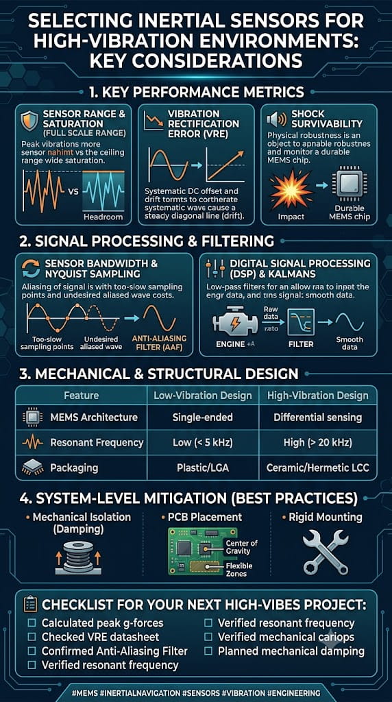
1. Introduction: Imagine a scenario where a welding robot operates continuously on an automotive assembly line, with the end of its robotic arm subjected to instantaneous shocks of 15g at a frequency of 80Hz. In this context, if the wrong IMU is selected, the bias drift of a standard sensor could accumulate to 1.2° within just 30 minutes, leading to positioning failure and a safety shutdown. This is no exaggeration. In high-vibration industrial environments—whether in stamping workshops, CNC machining, heavy-duty AGV operations, or heavy construction machinery—the challenge facing IMU sensors is not merely a matter of precision, but of fundamental viability. Vibration affects IMUs primarily through two channels: first, direct mechanical coupling, where vibration transmits through the mounting base to the sensor, interfering with the response of its micromechanical structure; second, Vibration Rectification Error (VRE), where the accelerometer’s DC rectification response to AC vibration generates an additional offset—a particularly critical issue for tilt-sensing applications. Furthermore, industrial environments experience drastic temperature fluctuations (-40°C to 85°C); since MEMS sensors are highly temperature-sensitive, an uncompensated gyroscope can exhibit bias drift on the order of ±10°/s. Therefore, selecting an IMU for high-vibration conditions requires addressing two core issues simultaneously: vibration interference resistance and temperature drift compensation. This article explores these two key aspects, systematically outlining the critical technical specifications and the decision-making process for product selection. 2. The Nature of Vibration Interference and Anti-Vibration Strategies 2.1. Understanding Vibration Rectification Error (VRE) In high-vibration environments, the most common failure mode for an IMU is not simply "inaccurate measurement," but rather "bias shift caused by vibration"—this is known as Vibration Rectification Error (VRE). For accelerometers, the sensor produces an unintended DC offset in response to AC vibration; such DC offsets are particularly detrimental in tilt-sensing applications. For gyroscopes, the primary issue is g-sensitivity, where linear vibration couples through the device's mechanical structure to superimpose a spurious angular rate signal onto the gyroscope's output. The combined effect of these issues can range from attitude drift to complete control system instability. 2.2. Mitigating Vibration at the Hardware Level When selecting products, priority should be given to IMUs featuring hardware-level vibration resistance designs rather than standard models that merely boast impressive specifications. The following vibration-resistant design features are key selection criteria: (1) Differential/Closed-Loop Sensing Architecture IMUs employing a differential gyroscope architecture can effectively suppress interference from linear acceleration and mechanical vibration. Closed-loop MEMS structures, combined with independent temperature compensation channels between the MEMS element and the ASIC circuitry, also significantly enhance vibration resistance. (2) Mechanical Filters and Vibration-Immune Designs Some industrial-grade sensors incorporate on-chip mechanical filters to attenuate high-frequency environmental vibration interference. For instance, Murata’s SCA3400 accelerometer utilizes a "vibration-immune design" capable of suppressing environmental vibration interference above 200 Hz. (3) Physical Isolation and Reinforced Packaging A dual-layer metal-ceramic housing combined with specialized damping materials can suppress mechanical noise coupling. The U4930 from Maixinmin Micro employs a hermetically sealed metal housing with specialized damping materials, suppressing mechanical noise interference while maintaining an IP67 protection rating. (4) Redundant Sensor Architecture A dual-IMU redundant architecture compensates for errors through real-time data comparison, further enhancing output reliability in high-vibration environments. 2.3. Suppressing Vibration Noise via Algorithms Even with optimal hardware selection, vibration noise cannot be entirely eliminated. Robust vibration-resistance solutions invariably incorporate noise reduction processing at the algorithmic level. (1) Adaptive Bandwidth Filtering One cutting-edge approach involves adaptive data preprocessing, where the filtering bandwidth is continuously adjusted via sinusoidal estimation to mitigate the impact of vibration and sensor noise prior to attitude estimation. Adaptive Kalman filter modules can dynamically adjust the noise covariance matrix and automatically optimize weighting based on external vibration frequencies, achieving an output noise density as low as 0.008°/s/√Hz. (2) Combination of Wavelet Filtering and Kalman Filtering Research indicates that by employing Gaussian-weighted moving average filtering combined with wavelet filtering for initial noise suppression, followed by PID-based fusion of the denoised data, and finally further optimization via Kalman filtering, the standard deviation of vibration noise can be reduced by 93.83%. (3) LMS and Extended Kalman Filter (EKF) Method For vibration scenarios such as vehicle bodies, the Least Mean Square (LMS) method can be used for front-end preprocessing to enhance the signal-to-noise ratio. Subsequently, the complementary characteristics of accelerometers and gyroscopes are utilized to filter out gyroscope bias noise, followed by final filtering using an Extended Kalman Filter. Results from a four-hour field experiment demonstrate that this method significantly reduces the impact of vehicle vibration on the IMU. 2.4. Key Selection Criteria for Vibration Environments When selecting a device, particular attention should be paid to the following vibration-related technical parameters: ` Vibration Rectification Error (VRE) / Vibration Rectification Coefficient: This is the most direct indicator of vibration resistance, typically measured in mg/g². Lower values indicate superior vibration resistance. ` Vibration Resistance: Expressed in grms (e.g., ≥20 grms or 10 g RMS over the 20 Hz–2 kHz range). ` Bandwidth Selection: Select a bandwidth that matches the target vibration frequency. An excessively wide bandwidth captures high-frequency in-band vibration, leading to higher VRE. Industrial-grade IMUs often intentionally limit output bandwidth to 100–200 Hz as an anti-aliasing design measure. ` Shock Tolerance: Typically required to be ≥2000 g or higher to ensure that accidental, severe shocks do not damage the IMU. 3. Temperature Drift Compensation Strategies and Accuracy 3.1. How Significant is the Impact of Temperature on IMUs? The sensitive structures of MEMS accelerometers and gyroscopes (such as silicon-based micromechanical beams, proof masses, and capacitive plates) undergo thermal expansion and contraction with temperature changes. This alters mechanical stiffness and capacitive gaps, resulting in output signal drift. For example, the Young's modulus of silicon decreases at a rate of approximately -60 ppm/°C as temperature rises; within the -40°C to 85°C range, the uncompensated bias drift of a gyroscope can reach the order of ±10°/s. Therefore, when selecting a device, one must focus on the IMU's stability across the full temperature range rather than relying solely on room-temperature specifications. 3.2. Technical Approaches to Temperature Drift Compensation Currently, there are two main technical paths for temperature drift compensation: Path 1: Hardware-level temperature compensation This involves integrating independent temperature sensors and compensation channels to monitor temperature and correct the output in real-time within the chip. Digital closed-loop systems are used to correct drift in real-time; for instance, the self-compensation feature in certain industrial-grade accelerometers can suppress temperature drift to ±0.003 mg/°C. Wafer-level encapsulation techniques and the selection of highly stable packaging materials help reduce thermal stress within the package. Path 2: Software/algorithm-level temperature compensation Software compensation relies on mathematical methods to analyze the relationship between temperature and the MEMS gyroscope's output data. It ensures output accuracy without incurring additional hardware costs, offering advantages such as simplicity, lower cost, and ease of parameter adjustment. Mainstream methods include polynomial fitting, piecewise linear/piecewise fitting, and interpolation techniques (such as Lagrange interpolation). Fundamentally, these methods predict and subtract temperature drift by establishing a mathematical mapping model between temperature and sensor error. The core concept involves using experimental data to train a function that maps temperature (or the rate of temperature change) to bias or scale factor corrections; during operation, the current temperature is input into this function to calculate the compensation value, thereby ensuring output stability across the entire temperature range. 3.3. Key Selection Metrics Related to Temperature Drift The following temperature-related parameters should be evaluated during the selection process: Full-temperature bias stability: Measures the variation in bias across the -40°C to 85°C temperature range, expressed in °/h or mg. High-quality industrial-grade IMUs can achieve a full-temperature bias of ≤150°/h (for gyroscopes). Bias temperature coefficient: Expressed in mg/°C or °/h/°C; lower values indicate better performance. For example, the accelerometer temperature offset is 0.026 mg/°C, while the gyroscope sensitivity temperature variation is only 0.0013%/°C. Temperature compensation method: Check the product specifications to see if they explicitly state the use of full-temperature-range calibration and compensation algorithms. Operating temperature range: Industrial grade is typically -40°C to 85°C, while more demanding applications may extend this range to -55°C to 125°C. 4. Selection Reference Based on Performance Grade For high-vibration industrial operating conditions, the following performance grade framework can be used as a reference for selection: Selection Grade Key Vibration and Temperature Compensation Characteristics Application Scenarios High-Performance Tactical Grade VRE 0.03 mg/g²; 10 g RMS vibration resistance; calibrated across the full -40°C to 71°C temperature range Robotics, navigation, stabilized platforms Industrial General-Purpose Grade -40°C to 85°C operating range; 0.026 mg/°C temperature drift; fault-tolerant design AGVs, agricultural machinery, precision GNSS Embedded Compact Grade Full-temperature compensation; ≥20 g RMS vibration resistance; ≥2000 g shock resistance Automotive, airborne, surveying and mapping High-Reliability/Long-Life Grade 10-year drift <0.5 mg; on-chip mechanical filter for vibration resistance (>200 Hz) Bridge monitoring, wind power, high-end equipment Redundant Dual-IMU Grade Dual IMU redundancy; IP67 protection; vibration damping; 0.5°/h bias stability Satellites, aerial surveying, harsh environments Summary When selecting an IMU for high-vibration industrial environments, the following key factors must be considered: (1) Vibration resistance: Focus on VRE (Vibration Rectification Error), vibration resistance ratings, mechanical filter design, and algorithmic noise reduction capabilities. (2) Thermal drift compensation: Focus on bias stability across the full temperature range, bias temperature coefficients, compensation algorithms, and wide-temperature calibration. (3) Comprehensive protection: Focus on shock resistance, IP protection ratings, and redundancy design. (4) Avoiding pitfalls: Relying solely on room-temperature specifications can be misleading; it is essential to request measured data regarding VRE and performance across the full temperature range. Ultimately, the selection of a suitable IMU should be based on a precise understanding of the specific application scenario—including vibration spectrum, temperature range, accuracy requirements, and installation space—alongside thorough communication with the supplier and, where necessary, empirical verification using prototypes.
Read More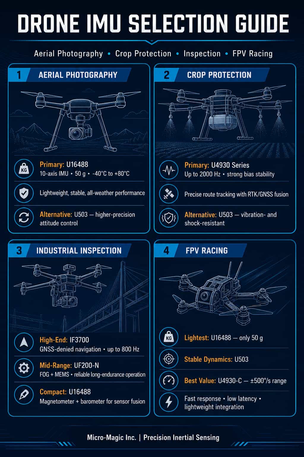
In the rapidly evolving drone industry, the Inertial Measurement Unit (IMU)—acting as the "sensory hub" of the flight control system—directly determines an aircraft's stability, precision, and reliability. Different application scenarios place vastly different demands on IMU performance: aerial photography drones prioritize ultra-stable image output; agricultural drones require precise flight path tracking; inspection drones demand long-duration, high-precision navigation; and racing drones prioritize dynamic response and lightweight design. As a leading domestic supplier of inertial sensors, Micro-Magic Inc. offers a comprehensive product portfolio ranging from MEMS inertial navigation modules to fiber-optic gyro systems, backed by extensive application experience in fields such as drones, autonomous driving, and robotics. This article focuses on four key drone segments—aerial photography, agricultural operations, inspection, and racing—and recommends the most noteworthy IMU models from Micro-Magic Inc. to assist developers in making precise product selections. I. Aerial Photography Drones: Ensuring Rock-Solid Stability in Every Frame For aerial photography drones, the core requirements for an IMU are high attitude accuracy, low noise, and excellent temperature stability. Whether for cinema-grade hexacopters or portable camera drones, the attitude data output by the IMU directly dictates the effectiveness of gimbal stabilization and overall image quality. Recommended Model: (1) U503 High-Precision 6-Axis MEMS Inertial Navigation Module The U503 is a high-precision, high-performance 6-axis MEMS inertial measurement module widely used in navigation, control, and measurement applications. Integrating high-performance sensors within a standalone unit—and featuring a hermetically sealed design and internal vibration damping—this module meets the rigorous demands of high-precision, high-dynamic navigation in harsh environments. In aerial photography scenarios, this ensures that the U503 provides stable, reliable attitude data to the flight controller even during strong winds or rapid maneuvers, effectively suppressing image jitter. (2) U16488 High-Performance MEMS IMU (Drop-in replacement for ADIS16488A) The U16488 is a high-precision, 10-axis MEMS inertial measurement unit integrating a tri-axial gyroscope, tri-axial accelerometer, tri-axial magnetometer, and barometer. It features a gyro bias instability as low as 0.5°/h (typical Allan variance) and an accelerometer bias instability of 20 μg. With its compact dimensions (47 × 44 × 14 mm) and lightweight profile (only 50 g), it is ideally suited for aerial photography drones with strict size and weight constraints. Additionally, the U16488 incorporates full-temperature calibration and compensation mechanisms, maintaining excellent measurement accuracy across a wide temperature range of -40°C to 80°C, thereby ensuring stable, high-quality aerial imagery output under diverse climatic conditions. II. Agricultural Spraying Drones: Precision Spraying Begins with Precision Sensing The operational characteristics of agricultural spraying drones dictate unique requirements for IMU performance: long-duration continuous operation, robust vibration resistance, and high-precision fusion with RTK/GNSS systems. Since these operations typically take place at low altitudes and low speeds in high-vibration environments, IMU bias stability and temperature drift control are critical. Recommended models: (1) U4930 Series High-Precision 6-Axis MEMS IMU (Drop-in replacement for HG4930) The U4930 series is a flagship industrial-grade MEMS inertial measurement module from Maixinmin Micro, available in three performance tiers: U4930-A, U4930-B, and U4930-C. The U4930-A model boasts a gyro bias instability as low as 0.03°/h, an angular random walk of only 0.02°/√h, and an accelerometer bias instability of 30 μg. This series supports a maximum data output rate of 2000 Hz and operates reliably within an ambient temperature range of -40°C to 80°C. For agricultural spraying drones, a 2000Hz update rate enables the real-time capture of even the slightest airframe vibrations and disturbances; combined with RTK/dual-antenna GNSS, this achieves centimeter-level flight path accuracy, effectively preventing overspraying or missed areas. Notably, the U4930 series serves as a direct drop-in replacement for the Honeywell HG4930, offering a cost-effective domestic alternative. (2) U503 (Also suitable for agricultural spraying applications) As previously mentioned, the U503 features internal vibration damping and exceptional vibration and shock resistance, making it ideally suited to the operational demands of agricultural drones, such as frequent takeoffs and landings and exposure to low-altitude vibrations. III. Inspection Models: Maintaining Heading in GNSS-Denied Environments Tasks such as power line, pipeline, and bridge inspections impose the most rigorous demands on IMUs, requiring long-duration pure inertial navigation capabilities, resilience against GNSS-denied conditions, and autonomous north-finding functions. Inspection drones often operate in areas where satellite signals are obstructed—such as near high-voltage towers, in canyons, or inside tunnels—requiring the IMU to independently maintain positional and attitude accuracy. Recommended Model: (1) IF3700 Satellite-Free Autonomous Navigation INS System The IF3700 is a high-end inertial navigation system developed by MaiXinMinWei specifically for satellite-free environments. It utilizes a high-precision closed-loop fiber-optic gyroscope (with a full-temperature bias stability of 0.01°/h) and a high-precision quartz accelerometer (20μg) to achieve high-precision pure inertial heading measurement. Its pure inertial performance is impressive: within one hour, the heading angle error is ≤0.01° (RMS), the attitude angle error is ≤0.005°, and the position error is ≤1 nautical mile/hour. In integrated navigation mode, heading accuracy is ≤0.02°, attitude accuracy is ≤0.005°, and RTK positioning accuracy is ≤2cm. It supports a maximum data update rate of 800Hz and offers multiple interfaces, including RS232, RS422, CAN, Ethernet, and USB. For aircraft such as large fixed-wing inspection drones and Vertical Take-Off and Landing (VTOL) UAVs, the IF3700 serves as a primary navigation unit. It maintains high-precision position and attitude output even when satellite signals are lost, ensuring the continuity and safety of inspection missions. (2) UF200-N High-Performance Fiber-Optic & MEMS Accelerometer Combined IMU The UF200-N is an Inertial Measurement Unit (IMU) based on high-precision fiber-optic gyroscopes and MEMS accelerometers. It adopts a modular design, offering high reliability and excellent cost-effectiveness. Its fiber-optic gyroscope features a measurement range of ±500°/s, a bias stability of 0.5°/h (10s smoothing), and an angular random walk as low as 0.02°/√h; the MEMS accelerometer offers a range of ±30g and a bias stability of 30μg. The UF200-N supports multiple interfaces, including RS422, RS232, and PPS; it has a steady-state power consumption of only 10W and weighs no more than 0.5kg. For medium-to-large inspection drones, the UF200-N provides high-precision, pure-inertial navigation capabilities within a lightweight package. It maintains stable position and attitude output even in complex environments where GNSS signals are unavailable, making it ideal for long-endurance missions—such as power grid and pipeline inspections—that demand strict precision and reliability. Additionally, its strong vibration and shock resistance allow it to fully meet the rigorous environmental requirements of industrial-grade inspection applications. (3) U16488 (Comprehensive Navigation with Magnetometer and Barometer) In addition to the high-precision MEMS IMU mentioned earlier, the U16488 integrates a three-axis magnetometer and a barometer, providing comprehensive environmental sensing capabilities. This makes it particularly suitable for inspection missions requiring multi-source data fusion: the magnetometer assists with heading calibration, while the barometer aids in altitude measurement, creating a triple-redundancy system that ensures the reliability of the inspection trajectory. IV. Racing Models: The Ultimate Pursuit of Speed, Precision, and Lightness The requirements for IMUs in racing drones (FPV drones) differ significantly from those in other applications: they demand ultra-high dynamic response, an extremely wide measurement range, minimal weight, and low-latency output. Every extreme roll, rapid dive, and instant acceleration pushes the performance limits of the IMU. Recommended Models: (1) U503 (Balancing Lightness and High Dynamics) Although positioned as a high-precision MEMS inertial navigation module, the U503 is designed with high-dynamic applications in mind. Its sealed housing and internal vibration-dampening design ensure stable attitude output even amidst intense vibration and shock. For professional-grade racing drones, it offers an ideal balance between precision and dynamic response capabilities. (2) U4930-B / U4930-C The U4930-B and U4930-C versions offer wider gyroscope measurement ranges (with the U4930-C reaching ±500°/s) while providing different trade-offs between bias stability and cost. For budget-conscious racing drone developers, the U4930-C delivers an ultra-wide ±500°/s range at a lower cost, fully capturing the high angular rate movements typical of competitive flight; meanwhile, the U4930-B version is available for professional racing models that demand higher precision. (3) U16488: The Ultimate Lightweight Choice Weighing just 50g, the U16488 is the lightest of the four recommended products—a crucial advantage for racing drones where every gram saved counts. Its dual SPI/UART communication interfaces also facilitate rapid integration with mainstream flight controller boards. V. Model Overview and Quick Selection Chart To facilitate quick comparison and selection, the table below summarizes the key features of the models recommended in this article: Model Product Type Key Advantages Data rate Weight Recommended Use Cases U4930 - A/B/C 6-Axis MEMS IMU Output rates up to 2000 Hz; high-precision accelerometer 2000 Hz 130g Plant protection, aerial photography U503 6-Axis MEMS IMU Internal shock absorption; resistant to vibration and shock 2000 Hz 220g Aerial photography, plant protection, racing U16488 10-Axis MEMS IMU Integrated magnetometer and barometer; ultra-lightweight design SPI/UART 50g Aerial photography, racing, inspection IF3700 Fiber-Optic INS/GNSS Integrated Navigation System Autonomous navigation without satellite signals; 0.003° attitude accuracy 800 Hz 7000g Inspection, industrial-grade aerial surveying UF200-N Fiber-Optic IMU Fiber-optic gyroscope and MEMS accelerometer; high reliability 200 Hz 500g Inspection, long-endurance flight VI. Model Selection Summary and Recommendations For aerial photography drones, the U16488 is the top recommendation; its ultra-lightweight design (50g) combined with full 10-axis functionality ensures a balance between image quality and flight endurance. If superior attitude accuracy is required, the U503 serves as an excellent alternative. For agricultural drones, the U4930 series is the primary choice. The U4930-A variant, in particular, offers the high stability and 2000Hz output rate needed to meet precision spraying requirements perfectly. Manufacturers requiring deep customization and integration can opt for the configurable version of the U4930A. For inspection drones, selection should be tiered based on budget and accuracy requirements: the IF3700 is the premier choice for high-end, large-scale drones, as its satellite-free autonomous navigation capability is crucial for inspection missions; the UF200-N (featuring a fiber-optic IMU) is suitable for mid-range models; and the U16488 is recommended for compact drones, offering the advantages of multi-source sensor fusion through its integrated magnetometer and barometer. For racing drones, balance is key. The U16488 represents the optimal solution for extreme weight reduction, while the U503 excels in stability during high-dynamic maneuvers; meanwhile, the U4930-C stands out as a cost-effective option offering an ultra-wide measurement range (±500°/s).
Read More
I. Brief Overview of IMU Underlying Architecture The core hardware of an Inertial Measurement Unit (IMU) consists of accelerometers and gyroscopes, which measure linear acceleration and angular velocity, respectively. Industrial-grade and higher-tier IMUs typically employ MEMS technology, while high-end units utilize fiber-optic or laser gyroscopes, paired with dedicated ASICs to perform signal conditioning, temperature compensation, and preliminary filtering. Accelerometers are based on a "spring-mass" model—where the displacement of a proof mass reflects acceleration; gyroscopes leverage the Coriolis effect—where a vibrating mass generates a measurable deflection when subjected to rotation. At the algorithmic level, the Extended Kalman Filter (EKF) fuses these two data streams: the gyroscope provides high-frequency attitude tracking, while the accelerometer (along with the magnetometer) performs long-term correction for drift. Pure inertial navigation derives attitude by integrating angular velocity and position by double-integrating acceleration; however, measurement errors amplify rapidly with each order of integration, resulting in "drift." Consequently, IMUs are typically classified into grades based on their bias stability: 1) Industrial Grade (Bias Stability: 1–10°/h): Suitable for short-duration dynamic scenarios—such as industrial robots, AGVs/AMRs, automated production lines, and high-end rehabilitation equipment—where there is a moderate requirement for long-term stability but significant sensitivity to cost. 2) Tactical Grade (0.1–1°/h): Suitable for applications requiring high dynamic response and short-duration autonomous navigation, such as missiles, UAVs, unmanned ground vehicles, eVTOL aircraft, and tactical weaponry. 3) Navigation Grade (0.001–0.1°/h): Suitable for missions requiring autonomous navigation over medium durations (ranging from tens of minutes to several hours) without external calibration, such as those involving commercial or military aircraft, ships, and medium-to-long-range missiles. With an understanding of this underlying architecture, the application logic for IMUs across various industries becomes clear: fundamentally, it involves making distinct trade-offs among "precision, real-time performance, reliability, and cost." II. Underlying Application Logic Across Various Industries 1. Autonomous Driving and High-Precision Positioning In autonomous driving and high-precision positioning scenarios, the core requirement is to achieve continuous positioning—particularly in GPS-denied environments such as tunnels and underground parking garages. The application logic involves utilizing the IMU as a reliable baseline for short-term positioning. This data is fused with inputs from GNSS, wheel odometers, and vision/LiDAR systems via tightly coupled Kalman filtering. By leveraging the high-frequency motion priors provided by the IMU (specifically angular velocity and acceleration), the system can maintain sub-meter-level position estimation for periods ranging from tens of seconds to several minutes even after GPS signals are lost. Simultaneously, through redundant design (e.g., equipping a single Level 4 autonomous vehicle with three IMUs), the system ensures safe degradation in performance in the event of a single-point failure. The fundamental logic here is to trade the cost of short-term integration drift for full-scenario availability. 2. Drones and eVTOLs In drone and eVTOL scenarios, flight control systems read angular velocity and acceleration data from the IMU at frequencies of several hundred Hertz, using a PID closed-loop mechanism to adjust motor speeds in real-time. When GPS signals are robust, the IMU assists with position control; however, in GPS-denied environments (such as indoors or within canyons), the IMU combines with barometers or optical flow sensors to enter a pure inertial navigation mode. For manned aircraft such as eVTOLs, additional requirements include compliance with airworthiness standards (e.g., DO-160G) and the adoption of redundant architectures (e.g., equipping a single aircraft with six IMUs). The core logic in this context is characterized by "high frequency, low latency, and short-term autonomy." 3. Industrial Robots and Mobile Robots The core requirements for industrial robots and mobile robots are precise position control and long-term stability, aimed at enhancing repetitive positioning accuracy and the robustness of SLAM (Simultaneous Localization and Mapping) systems. In industrial robotic arms, tactical- or navigation-grade IMUs monitor the motion trajectories of individual joints in real-time, providing closed-loop corrections to motor commands to achieve a repetitive positioning accuracy of ±0.02 mm. In AGVs (Automated Guided Vehicles) and AMRs (Autonomous Mobile Robots), the IMU provides the SLAM system with continuous, short-term motion priors; when LiDAR systems fail due to occluded fields of view or insufficient environmental features, the integrated data from the IMU "bridges" these information gaps, thereby maintaining the continuity of pose estimation. The fundamental logic here is "high-precision short-term estimation to fill sensor blind spots." 4. Defense and Aerospace The core requirements in the defense and aerospace sectors are full-lifecycle reliability in extreme environments and autonomous navigation capabilities that function for extended periods without external calibration. Strategic-grade (or navigation-grade) IMUs—typically utilizing fiber-optic or laser gyroscopes—are designed to serve as completely independent sources of information. Their underlying logic is rooted in a combination of "full-spectrum error modeling" and "thermodynamic compensation." During critical phases such as launch, flight, or underwater submersion, these IMUs must withstand high g-forces, wide temperature fluctuations, and intense electromagnetic interference; simultaneously, through exceptionally precise bias stability and random walk specifications, they ensure that positional errors remain bounded over durations spanning hours or even months. Furthermore, domestic production and technological autonomy have become absolute imperatives within this field. 5. Medical Surgery and High-End Rehabilitation The core requirements in medical surgery and high-end rehabilitation are a high dynamic range and high repeatability in the quantification of biomechanical parameters. In orthopedic surgical navigation, IMUs are affixed to surgical instruments or the patient's skeletal structure; utilizing six-degrees-of-freedom (6-DOF) pose tracking, they map the real-time position of the instruments onto pre-operative medical images. The underlying logic here is to leverage the short-term precision of tactical-grade IMUs to circumvent the occlusion-sensitivity issues inherent in optical navigation systems. In gait analysis, IMUs are worn on the limbs to capture parameters such as joint angles and acceleration; these data are then processed via sensor fusion algorithms to generate clinical metrics such as step frequency and gait symmetry. Fundamentally, this application represents "wearable, wireless, and high-dynamic-range motion quantification." Summary The fundamental application logic of IMUs across various industries can be broadly summarized as follows: leveraging their inherent advantages—specifically their independence from external signals and their high-frequency response capabilities—to address either the "problem of spatiotemporal continuity in GPS-denied environments" or the "problem of real-time closed-loop control of motion states," all within a specific, requisite level of precision. The varying requirements across different industries—regarding bias stability, dynamic range, and environmental adaptability—dictate the specific selection of IMUs, ranging from tactical-grade to strategic-grade devices. Nevertheless, the shared engineering logic underpinning all these applications remains constant: trading off a controllable degree of integration drift in exchange for an indispensable capability for autonomous situational awareness.
Read More
Inaccurate measurement of the lever arm between IMU (Inertial Measurement Unit) and GNSS (Global Navigation Satellite System) antennas is a common source of error in GNSS/INS integrated navigation systems. This error significantly affects the accuracy of integrated navigation under dynamic conditions, especially during rotational motion. Usually, the following methods are used to compensate for the errors in the integrated navigation system caused by the influence of the lever arm. 1. Offline Calibration: Before the system is put into use, the lever arm vector is accurately estimated through specific testing maneuvers. Usually, static multi position method and dynamic maneuver method ("8" or snake maneuver) are used. If the maneuvering design is appropriate and the data quality is high, very accurate estimates of the lever arm can be obtained. 2. Online Estimation: During the operation of a integrated navigation filter (usually a Kalman filter or its variants such as EKF, UKF), the lever arm vector is used as part of the state variable for real-time estimation. It does not require additional offline testing and can gradually correct lever arm errors during normal system operation. 3. Adaptive/Robust Filtering: When the arm error cannot be accurately known and the online estimation effect is poor (such as insufficient carrier mobility), adjusting the filter parameters can tolerate or weaken the influence of arm error, prevent filter divergence, or provide overly optimistic accuracy evaluation. It is recommended to prioritize offline calibration. If conditions permit, conducting specialized dynamic maneuvering calibration is the best method to obtain high-precision lever arm values. Secondly, online estimation is implemented to estimate the lever arm vector as a state variable in the integrated navigation filter. This is the most commonly used and effective real-time processing method in engineering practice. Be sure to ensure that the carrier has sufficient rotational maneuverability to make the lever arm observable. Finally, combining adaptive/robust strategies to prevent severe performance degradation or divergence.
Read More
In the field of inertial technology, accuracy has always been the core metric for evaluating IMU value. The U503 series MEMS inertial measurement module introduced by Micro-Magic Inc, with its precision comparable to fiber optic gyroscopes, stable performance across the entire temperature range, and rugged design resistant to harsh environments, plays a pivotal role in the application of unmanned systems. Ultra-High Precision Technical Performance The gyroscope performance of the U503 has reached the top level of MEMS devices, with bias instability (Allan variance) ≤0.03°/h, reflecting the device's stability over long time scales and determining the attitude-holding capability of pure inertial navigation. The angular random walk is ≤0.005°/√h, indicating the extremely low gyroscope noise level of the U503, with an angle error of only about 0.3° after 1-hour integration. The accelerometer of U503 has also reached the top level of industrial grade, with zero bias instability (Allan variance) ≤3μg and excellent long-term stability, supporting high-precision inclination measurement and gravity field modeling. The speed random walk is ≤ 0.01m/s/√ h, and the velocity integration error is extremely low, with a speed error of only about 0.6m/s per hour. U503 is not simply an integration of "gyroscope+accelerometer", but achieves optimal overall performance through system level design. The gyroscope and accelerometer data are strictly aligned, achieving microsecond level delay output and supporting the application scenario of high dynamic integrated navigation. U503 has achieved cross coupling suppression between sensitive axes, with inter axis coupling of ≤0.001rad, ensuring the orthogonality of three-axis measurements and reducing coordinate system conversion errors. At the same time, U503 has built-in self-test and status word output, which can identify and isolate abnormal situations in a timely manner, achieving real-time monitoring of the status. System-Level Assurance Behind Accuracy The ultra-high precision of U503 is not an isolated indicator, but is built on a complete system design. Through full temperature calibration compensation, the zero bias change within the full temperature range is ≤ 20% of the nominal value; Through internal shock-absorbing structure and system sealing design, vibration noise above 1000Hz has been suppressed; By shielding with a metal casing and designing a power filter, EMI interference on analog signals is reduced; Real time output of status words and self check for anomalies to ensure the reliability of output data.. The Core Role of U503 in Unmanned Systems In GNSS/INS integrated navigation systems, IMU provides high-frequency and high-precision relative motion information. The ultra-high precision of U503 extends the survival time when GNSS signals are interrupted. When unmanned vehicles enter tunnels or drones fly over urban canyons and GNSS signals are lost, the system enters pure inertial navigation mode. The position error of 60 second pure inertial navigation is less than 5 meters, and 300 second pure inertial navigation can still maintain meter level positioning . This means that unmanned systems can rely on inertia to maintain navigation capabilities for a longer period of time until the GNSS signal is reacquired or autonomous landing/parking is completed. In underground mining, tunnel construction and other scenarios, the ultra-low drift characteristics of U503 enable it to support the strapdown inertial navigation system to complete pure inertial positioning for tens of minutes, and integrate with odometer/wheel speed meter to achieve sub-meter level positioning accuracy. In scenarios such as drone catapult takeoff, unmanned vehicle collision testing, and missile initial flight, U503 can independently capture the angular velocity and acceleration of the impact process with high bandwidth, and integrate them to obtain attitude changes and velocity trajectories. U503 does not compromise on dynamic performance while pursuing accuracy. Its bandwidth of ≥200Hz covers the vibration frequencies of UAV rotors and the motion frequency bands of unmanned vehicle suspensions, fully preserving dynamic information. The measurement ranges of ±300°/s and ±30g meet the high-maneuverability requirements of most unmanned systems, preventing sensor saturation. With a maximum data update rate of 2000Hz, it provides real-time feedback for high-speed control loops. This enables the U503 to maintain stability at an ultra-high precision level in static scenarios, while accurately capturing intense motion without distortion in high-dynamic scenarios. The U503 series MEMS IMU modules, with their precision comparable to fiber optic gyroscopes, stable performance across the full temperature range, and rugged design resistant to harsh environments, provide unmanned systems with a true "high-precision perception core." U503
Read Moreleave a message
Scan to Wechat :
