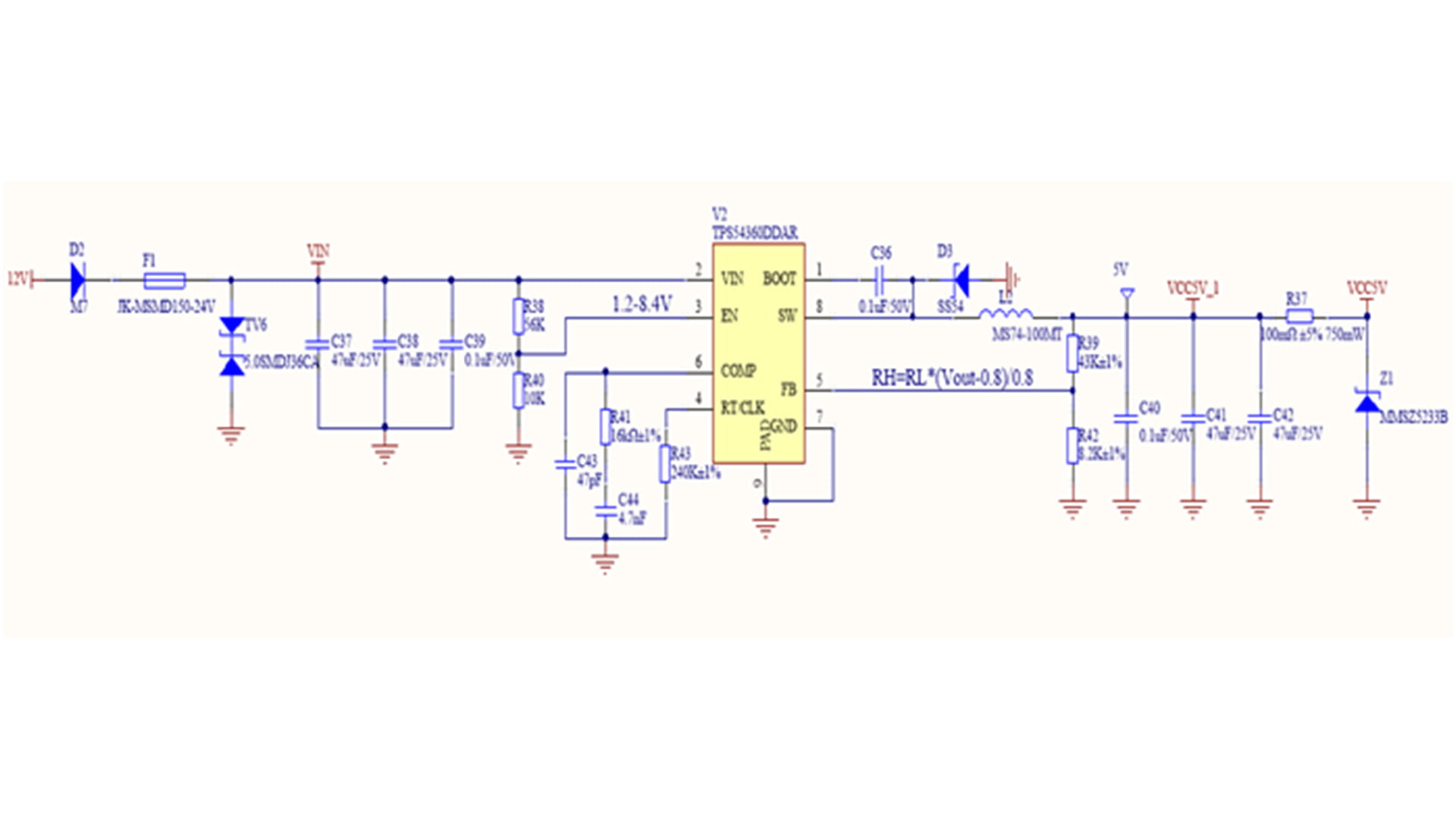
Figure 1. Non-synchronous BUCK converter topology Figure 1 shows the topology of an asynchronous BUCK converter. Asynchronous BUCK converter chips typically integrate only the high-side MOSFET internally. A freewheeling diode needs to be installed between the SW pin and GND as the freewheeling path for the power inductor when the high-side MOSFET is turned off. The selection of the freewheeling diode must meet at least the following two hard criteria (1)(2) and two optimization criteria (3)(4): (1) The reverse operating voltage VRRM of the freewheeling diode must be equal to or greater than the maximum input voltage VIN(max). (2) The forward conduction current IF(AV) of the freewheeling diode must not be less than Iout(max)*(1-D), where D is the duty cycle of the buck converter, and Iout(max) is the maximum load current that the buck converter can support. For a more stringent selection of the freewheeling diode's overcurrent capability, it can be selected to be greater than or equal to the peak current on the inductor IOUT+(ΔIL)/2. (3) The smaller the forward voltage drop VF, the smaller the power loss caused by this parameter, and the higher the power efficiency. (4) The faster the switching speed from the on state to the off state (the smaller the reverse recovery time trr), the smaller the reverse recovery loss, and the higher the power efficiency, the better. Schottky barrier diodes (SBDs) are ideal choices for freewheeling diodes due to their small forward voltage drop and fast reverse recovery time (typically tens of nanoseconds or even a few nanoseconds), reducing power losses in the freewheeling diode. To design a step-down DC-DC converter with a DC input voltage range of 9-36V, a typical input voltage of 12V, an output voltage of 5V, and a maximum load capacity of 5A, a Schottky diode with a reverse operating voltage of 40V and a forward current greater than 5A is selected because its maximum input voltage is 36V. As shown in Figure 2, the SS54 Schottky diode has a reverse operating voltage of 40V, an average rectified current of 5A, and a maximum forward voltage drop of 0.55V at a forward current of 5.0A, meeting the circuit requirements. Figure 2 Electrical parameters of SS54 Schottky diode When the input voltage is a typical 12V, the duty cycle is a typical 5/12, and the average current flowing through the freewheeling diode is 5.0A*(1-5/12)=2.917A. When the input voltage is the maximum value of 36V, the duty cycle is a minimum of 5/36, and the maximum average current flowing through the freewheeling diode is 5.0A*(1-5/36)=4.3A. As shown in Figure 3, D3 (SS54) in the TPS54360DDAR circuit design example is the selected freewheeling diode. Figure 3. TPS54360DDAR circuit design example
Read More
Significant progress has been made in the field of inertial technology in China - Micro Magic Inc recently announced that its high-performance inertial navigation system IF3700 has been successfully applied to the industry-leading "Tianhang Intelligence" new generation high-end industrial drone platform. This cooperation marks a comprehensive breakthrough in key indicators such as adaptability to complex environments and long-term stability for domestically produced high-precision inertial sensors, providing a core guarantee for reliable operation of industrial drones in challenging scenarios. In professional scenarios such as power inspection, high-altitude surveying, and emergency reconnaissance, industrial drones often face severe challenges such as strong electromagnetic interference, severe temperature changes, and continuous body vibration. The performance fluctuations of traditional sensors can easily lead to positioning drift and attitude misalignment, directly affecting operational safety and data quality. The technical director of "Tianhang Intelligence" said, "We have been looking for a sensor that can provide stable and accurate heading and attitude measurement throughout the entire mission cycle, and the appearance of IF3700 is timely." The successful application of IF3700 is attributed to its outstanding performance in multiple key performance parameters, which directly determine the reliability of drone navigation systems under extreme conditions. The IF3700 adopts a high-precision closed-loop fiber optic gyroscope with a full temperature of 0.01°/h and a 20 μg high-precision quartz accelerometer, with autonomous compass function. It can still achieve attitude accuracy of ≤ 0.003° and heading maintenance accuracy of ≤ 0.01°/h in pure inertia mode, demonstrating strong environmental adaptability. At the same time, the system supports inertial/satellite integrated navigation mode, with a position accuracy of centimeter level (RTK mode) and a velocity accuracy of better than 0.02m/s, effectively improving the operational capability of unmanned aerial vehicles in GNSS signal interference prone areas such as urban canyons and forest areas. In addition, IF3700 has rich interface configuration and high data update rate (up to 800Hz), which can flexibly interface with flight control, load and ground station systems, meeting the strict requirements of real-time and integration for industrial grade drones. The "Tianhang Intelligent" drone equipped with the IF3700 inertial navigation system has been validated for its value in multiple harsh scenarios. In surveying missions over complex plateau terrain, even with weak GPS signals, the IF3700 maintained centimeter-level flight path accuracy through its stable system output, successfully accomplishing high-precision 3D modeling. During high-voltage live-line inspection tasks, even when operating in strong electromagnetic environments, the IF3700 system remained completely immune to interference, delivering robust and reliable navigation and attitude data that formed the core foundation for autonomous obstacle avoidance and precise hovering. In emergency supply delivery operations, despite enduring substantial temperature variations during long-endurance, day-and-night missions, the IF3700 system demonstrated exceptional temperature stability, ensuring no degradation in navigation accuracy throughout the entire process. Micro Magic's Product Manager stated: "The success of the IF3700 system in the high-end industrial drone sector is just the beginning. It demonstrates that domestic core sensors are fully capable of supporting the development needs of intelligent equipment. We will continue to deepen our expertise in inertial technology, providing more unmanned platforms with a precise and reliable 'Perception Heart'."
Read More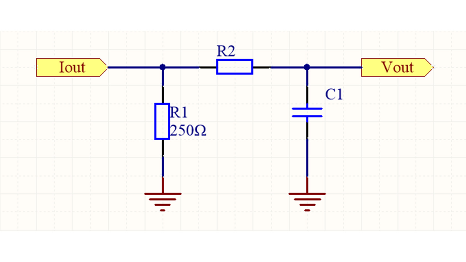
The previous article mentioned that in order to suppress the influence of high-frequency noise, the 4-20mA current sampling circuit needs to add an RC low-pass filter before ADC sampling. The RC low-pass filter circuit shown in Figure 1 is adopted, where R2 is 1.6K and C1 is 0.1uF. Then the cutoff frequency fc is approximately 1KHz. Figure 1 RC low-pass filter The following analysis examines its noise suppression capability through practical calculations, using a 200Hz in-band signal and a 5kHz out-of-band noise signal as examples to calculate its amplitude-frequency response. The output of a typical resistor divider is shown in Figure 2. Figure 2 Resistor voltage divider output The RC filter uses an equivalent structure, replacing R2 with a capacitor. First, we replace R2 with the capacitive reactance (XC) of the capacitor, obtaining the output expression of the RC voltage divider as shown in Figure 3: Figure 3. Resistor-capacitor voltage divider output The expression for the capacitive reactance of the capacitor is as follows: Figure 4. Expression for capacitive reactance of a capacitor In the design example above, R ≈ 1600Ω and C = 100nF. We assume the amplitude of VIN is 1V, and calculate the amplitude of VOUT using a sine wave frequency of 200Hz (Figure 5): Figure 5 The calculation results in Figure 5 show that the amplitude of the 200Hz signal remains essentially unchanged, which is consistent with the expectation of maintaining the signal amplitude without attenuation while suppressing noise. Next, let's see how the filter successfully attenuates the 5kHz noise component (Figure 6). Figure 6 The calculation results in Figure 6 show that the noise amplitude is only about 20% of its original value, which demonstrates that the suppression effect on out-of-band noise is significant.
Read More
In the complex and ever-changing fields of industry and research, the accuracy and reliability of navigation systems directly determine the success or failure of tasks. The IF3900 series high-precision fiber optic inertial navigation system launched by Micro-Magic Inc., with its groundbreaking technical design and exceptional performance, delivers innovative solutions for premium application scenarios including aerospace, autonomous driving, marine exploration, and UAV navigation. The IF3900 series products are equipped with high-precision closed-loop fiber optic gyroscopes and high-precision quartz accelerometers, and use multi-sensor data fusion technology to combine inertial measurement with GNSS, achieving long-term high-precision integrated navigation. At the same time, IF3900 has post-processing capabilities, which can improve the heading, attitude, and position accuracy of the product through post-processing software. Core Advantage: Perfect Integration of Precision and Reliability 1. Features industry-leading ultra-high precision performance The IF3900 series products are equipped with high-precision closed-loop fiber optic gyroscopes with zero bias stability of 0.001°/h, achieving extremely low drift in all temperature environments to ensure long-term stability of attitude and heading; The built-in high-precision quartz accelerometer has a zero bias stability of up to 10μg, which can accurately sense the motion of the carrier, with no delay in dynamic response, suitable for high-speed and high maneuverability scenarios; At the same time, by integrating multi-sensor fusion technology and combining GNSS with inertial measurement data, even if satellite signals are temporarily lost, centimeter level positioning accuracy can still be maintained through pure inertial navigation. 2. Intelligent post-processing elevates performance to the next level Supporting differential reference stations and post-processing software, the heading accuracy can reach 0.002° (RMS) through algorithm optimization, and the position accuracy can be improved to RTK 2cm+1ppm, meeting the high requirements for data backtracking in scientific surveying, geological exploration, and other fields. 3. Flexible configuration and seamless integration Supports single/dual antenna mode, multi protocol output (RS232/RS422/CAN/Ethernet/USB), with a data update rate of up to 800Hz, compatible with Novatel post-processing software, and easy integration with existing systems. By intelligently compensating for lever arm errors, the offset between GNSS antenna and inertial navigation center can be calibrated with just one click, ensuring data consistency in complex installation scenarios. 4. Strong and durable, Fearless of challenges Through comprehensive vibration testing, covering 20~2000Hz wideband random vibration, multi axis composite sweep frequency, and transient impact (half sine wave 11ms/30g), the overall structural stability and functional integrity of the system under extreme mechanical environments have been verified. Through vibration temperature electromagnetic multiphysics coupling testing, the system is still able to converge quickly, demonstrating its ability to quickly recover under strong disturbance conditions. Application Scenario: Empowering High-End Fields ⚪ Automatic driving and intelligent transportation: provide real-time vehicle attitude, position and speed information to help auto drive system above L4 achieve centimeter level positioning. ⚪ Drones and robots: Maintain stable navigation in indoor or complex terrain without GPS signals, support precise hovering and path planning. ⚪ Surveying and Exploration: The ability for high-precision positioning and continuous navigation ensures the continuity and accuracy of surveying and exploration work ⚪ Aerospace and Defense: precise guidance and attitude control in high dynamic environments to meet military grade reliability requirements. Technical Parameter Highlights ⚪ Attitude accuracy: ≤ 0.002° (RMS), with an error of ≤ 0.005° when maintaining pure inertia for 1 hour. ⚪ Speed accuracy: ≤ 0.02m/s (in combination navigation mode), ≤ 0.1m/s in pure inertia mode. ⚪ Rich interfaces: 4-channel RS422, 1-channel CAN, 1-channel Ethernet, USB, and multi-channel satellite antenna interfaces. ⚪ Power consumption and volume: ≤ 35W power consumption, compact design (190 × 190 × 166mm), weight ≤ 8.5kg, suitable for space limited carriers. IF3900 series product, with its high-precision inertial components, multi-source data fusion capabilities, and flexible post-processing capabilities, has become an ideal choice for reliable navigation in complex environments. Users can fully utilize protocol interfaces for customized development to adapt to diverse application requirements .
Read More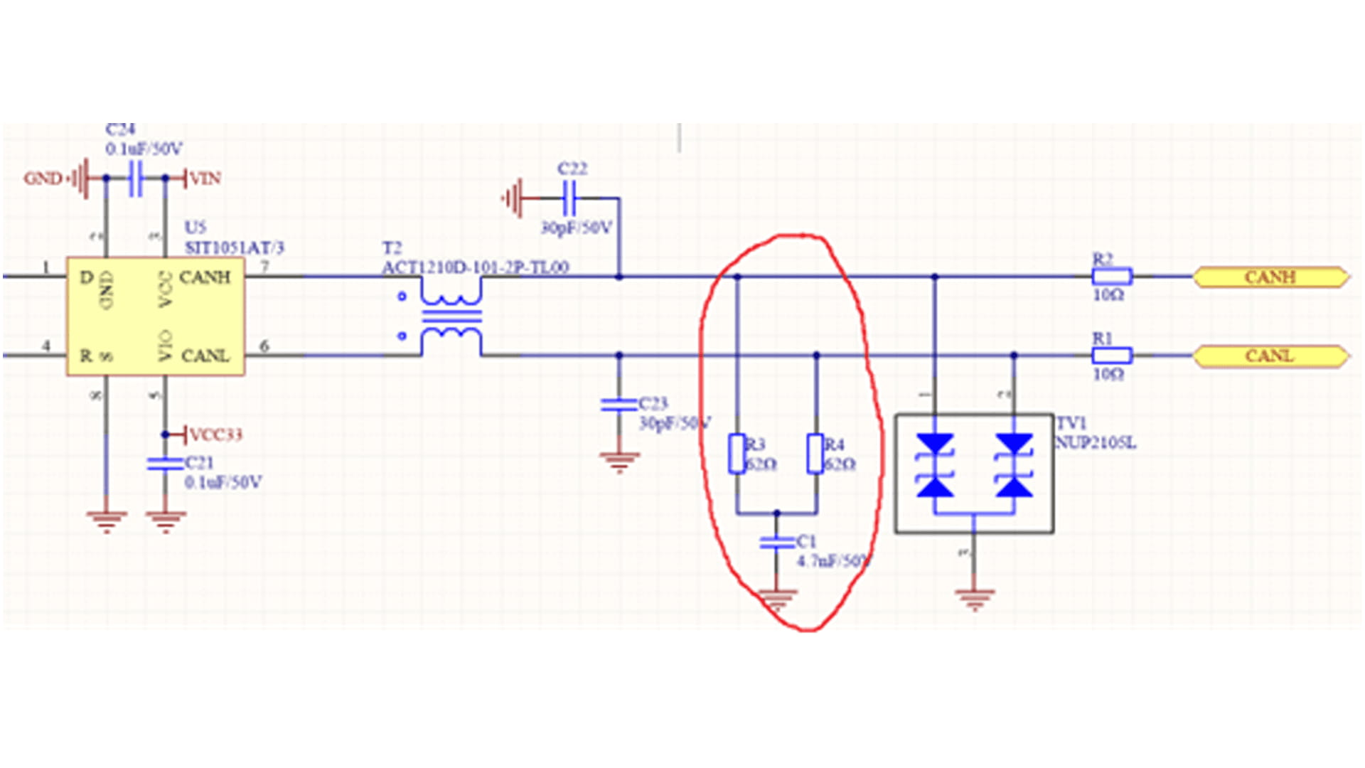
We often see the design circuit shown in the figure below in CAN communication: the CAN terminal resistor does not directly use 120 ohms. Instead, a grounded capacitor is added between two 62Ω resistors to "split" the terminal resistor into two parts, which is the split termination method. Figure 1 CAN bus interface circuit This connection method is actually quite sophisticated; it effectively reduces external interference on the differential signal. The CAN bus transmits differential signals, which are generally highly resistant to common-mode interference. However, for high-reliability design, the CAN bus must withstand a variety of harsh environments. High-amplitude common-mode spike interference on the bus can damage the ground-connected circuitry within the CAN transceiver, necessitating interference suppression. The simplest and most effective method for suppressing this interference is to use an RC low-pass filter. This involves splitting the 120Ω termination resistor into two 62Ω resistors connected in series, with a small capacitor connected to ground between the two resistors. This creates an RC low-pass filter at each of the two differential transmission ports, CANH/CANL, on the CAN bus. The cutoff frequency of an RC low-pass filter is Fc = 1/(2πRC), so C = 1/(2πRFc). This means that the size of the capacitor is related to the signal transmission cutoff frequency. The choice of capacitor is typically determined by the baud rate. For a 500kHz baud rate, we choose a cutoff frequency of 500kHz. The capacitance calculation formula is: C = 1/(2πRFc) = 1/(2π*500000*62) = 5.13nF. A capacitor of 4.7nF, which is close to the commonly used value, is sufficient. The CAN bus uses split termination to more effectively filter out high-frequency common-mode noise, improving communication stability in complex industrial environments.
Read More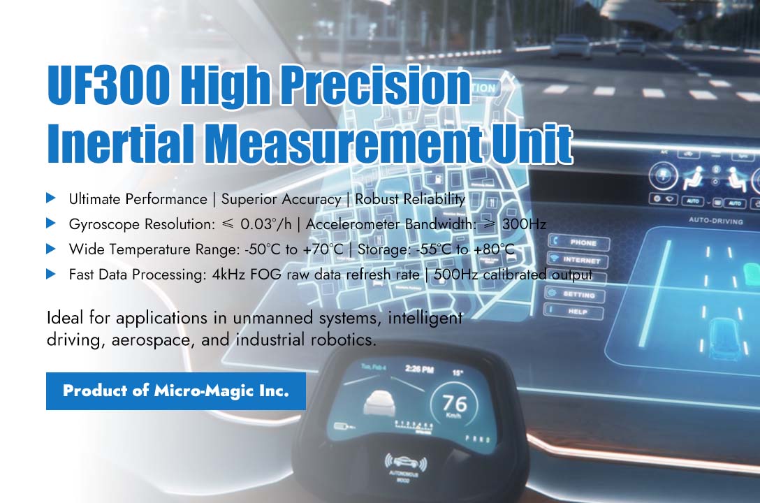
Micro-Magic Inc has launched a high-precision imu UF300, specifically designed for navigation systems. With cutting-edge fiber optic gyroscope technology as its core, it integrates high precision, miniaturization, and strong reliability, and is specially designed for intelligent equipment in harsh environments. Whether it's the agile handling of drones, the millisecond level response of intelligent driving, or the ultimate precision of missile flight control. The UF300 achieves a top-level accuracy in the industry with a 0.03°/h gyroscope zero bias stability and a 3×10^-5 g accelerometer zero bias stability, which is an order of magnitude higher than mainstream specifications. The UF300 series high-precision inertial measurement unit consists of three solid-state fiber optic gyroscopes, three quartz accelerometers, and a data packaging board. It adopts three-axis sharing technology and is designed for the needs of high-precision application backgrounds. The sensitive ring of the fiber optic gyroscope adopts magnetic shielding, and by reducing its diameter, it not only reduces the volume of the inertial component, but also improves the performance of the inertial component under vibration environment. The IMU platform with spatial diagonal damping layout ensures that the IMU components of the strapdown system have good isotropic dynamic response characteristics under vibration and impact conditions. FPGA circuit design can improve product performance in key indicators and overcome the limitations of analog signal processing, eliminating temperature sensitive drift and rotation errors. Main features of UF300 1. Ultimate Performance, Fearless of Limits ⚪ High precision perception: gyroscope resolution ≤ 0.03°/h, accelerometer bandwidth ≥300Hz, dynamically capturing subtle movements at every moment, with errors approaching zero. Adaptive filtering technology reduces zero drift and angle random walk by 50% -75%. ⚪ Super environmental adaptability: The working temperature ranges from -50 ℃ to +70 ℃, and the storage temperature covers from -55℃ to +80℃. It is stable from the polar regions to the desert. ⚪ High speed data empowerment: 4kHz FOG raw data refresh rate and 500Hz compensated calibrated gyroscope and accelerometer incremental information output, millisecond level response, providing delay free decision support for real-time control. 2. Lightweight Design, Flexible Adaptation ⚪ Small size and light weight: only 1800g±50, compact structure easily integrated into space limited equipment such as drones and robots. At the same time, the size can be reduced according to customer requirements, and reflector can be installed on the X and Y axes to meet customized needs. ⚪ Military grade reliability: No moving parts, all solid-state design, impact and vibration resistance, with a lifespan of up to 100000 hours, completely eliminating the hidden danger of mechanical wear and tear. 3. Versatile interface, seamless integration ⚪ Efficient power supply: Supports 28V wide voltage power supply with ripple ≤ 200mV, ensuring pure power supply under complex working conditions. ⚪ Multi-channel high-speed communication: RS-422 dual channel output, supporting custom transmission rates, compatible with mainstream control systems, data frame checksum design, ensuring zero information errors. Application Scenario - Precision is Everywhere ⚪ Unmanned system: Unmanned aerial vehicle precise hovering, autonomous obstacle avoidance, UF300 injects "super sensory nerves" into flight control. ⚪ Intelligent driving: The "invisible helmsman" of L4/L5 level autonomous driving, which perceives the body posture in real time and ensures driving safety. ⚪ Aerospace: from missile guidance to satellite attitude control, millimeter-level precision governs thousand-kilometer trajectories, where infinitesimal errors translate into mission-critical deviations. ⚪ Industrial robot: A "dynamic balancer" for high-speed robotic arms, achieving micrometer level motion trajectory control. Technical Details Showcase Hardcore Strength 1. Core parameters of fiber optic gyroscope: ⚪ Measurement range: ±300°/s, dynamic full coverage; ⚪ Random walk coefficient ≤ 0.003 °/√ h, leading the noise suppression industry; ⚪ Scale factor nonlinearity ≤ 10ppm, linear output without distortion. 2. Core parameters of accelerometer: ⚪ Range -10g to +10g, Precision measurement of instantaneous acceleration. ⚪ Bandwidth ≥ 300Hz, High-frequency vibrations cannot escape detection. Born for the Future, Fighting for the Ultimate UF300 is not only a product, but also synonymous with precise measurement. It helps customers break through technological boundaries and open a new era of intelligent equipment with military grade quality, aerospace grade precision, and industrial grade durability.
Read More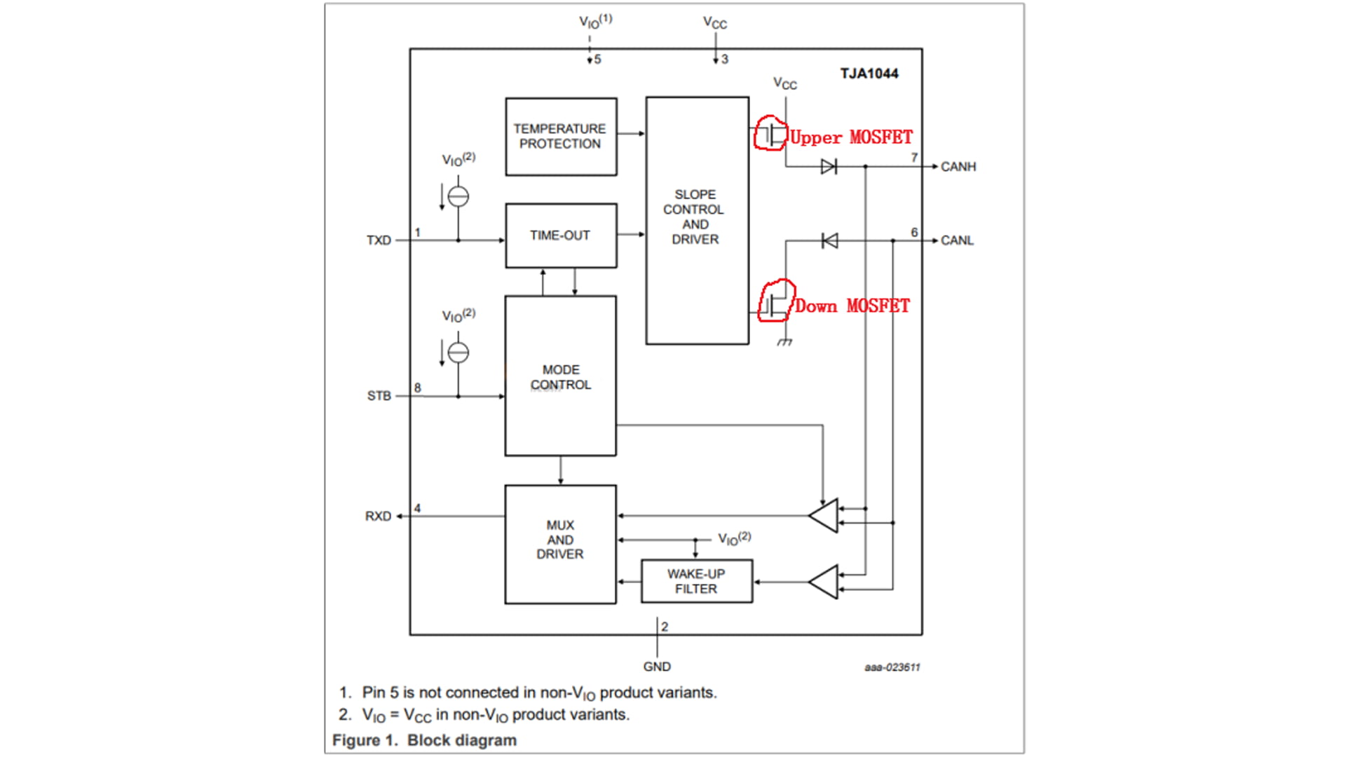
In the actual use of the CAN bus, as shown in Figure 1, a 120Ω resistor needs to be connected at both ends of the bus. So what is the basis for using a 120Ω resistor? Figure 1 Below we take the internal architecture diagram of TJA1044 as an example for analysis. Figure 2 The CAN bus's characteristic is that dominant represents 0, and recessive represents 1. When the bus is recessive, both the upper and lower transistors Q1 and Q2 within the TJA1044 are turned off, leaving CANH and CANL inactive with a voltage difference of 0V. When the bus is dominant, both the upper and lower transistors Q1 and Q2 within the TJA1044 are turned on, creating a voltage difference between CANH and CANL. If there is no load on the bus and the bus is recessive, the bus's differential resistance will be very large, causing even minimal external energy to cause the bus to become dominant. This is primarily because the minimum threshold voltage for dominant in typical transceivers is only around 500mV. Therefore, to improve the bus's immunity to interference, a termination resistor is required. However, this resistor should be kept as low as possible (and also to avoid excessive current). In addition, parasitic capacitance on the bus must also be considered. When the bus is dominant, the capacitor charges, and when it is recessive, the capacitor discharges. If the bus does not have any parallel resistors, the bus can only discharge through the transceivers at both ends. This affects the transition time between the two states (recessive and dominant), resulting in waveform anomalies (climbing), as shown in Figure 3. When a signal encounters an impedance discontinuity in a high-speed transmission path, it causes signal reflections, which we call impedance discontinuities. Adding terminal resistors can eliminate or reduce the impact of these signal reflections. The terminal resistors absorb signal energy, preventing it from dispersing on the bus. So why 120Ω? In fact, the ISO 11898-2 standard clearly defines 120Ω as the most reasonable resistance value determined through extensive experimental testing. Figure 3 If you want to verify how large the terminal resistance of the bus is required in an actual project, you can test it using the method shown in Figure 4 below. Figure 4 Connect an adjustable resistor in parallel to the bus and adjust it until the square wave waveform remains undistorted. When selecting the terminal resistor power, the short-circuit condition of the interface must be taken into account. This means that in the event of a short circuit, the short-circuit current will flow directly from CANH to CANL. However, the current that a typical CAN transceiver can withstand is only tens of mA (due to internal current limiting measures within the transceiver). For example, the TJA1044 only handles 50 mA. Based on P = I² * R, we get 50 mA * 50 mA * 120 Ω = 0.3 W. Therefore, the resistor power is selected to be 0.25 W, which is the common 1206 package.
Read More
In the design of high-precision inclination measurement systems, error control is the key to determining system performance. This article combines existing research results and engineering practice to discuss implementation methods, error sources, analysis methods, and solutions from four aspects, providing reference for the design and optimization of high-precision inclination measurement systems. 1. How to use MEMS accelerometers to achieve tilt angle measurement The principle of measuring tilt angle with an accelerometer is based on the vector decomposition of gravitational acceleration. Under static or quasi-static conditions (without external acceleration interference), when the device tilts, the components of gravity acceleration on the three orthogonal axes (X, Y, Z) of the accelerometer will change. By measuring the proportions of these components, the tilt angle of the device relative to the direction of gravity can be calculated. As shown in the above figure: Among them, reflects the angle between the horizontal plane and the X-axis; reflects the angle between the horizontal plane and the Y-axis. 2. Analysis of main sources of error 1) Environmental interference error ⚪ Mechanical vibration: When sensors are installed in a vibrating environment, vibration can cause fluctuations in the output signal, such as in vehicle platforms or industrial equipment scenarios, where vibration may introduce a measurement deviation of ±0.5°. ⚪ Temperature drift: Temperature changes cause sensor zero drift, especially when the operating temperature exceeds the calibration range (such as -20℃~65 ℃), the error can reach 0.002°/℃. ⚪ Electromagnetic interference: Power fluctuations or external electromagnetic fields may interfere with the sensor signal chain, affecting the accuracy of analog-to-digital conversion. 2) Sensor self-error ⚪ Nonlinear error: The output of MEMS tilt sensors has a nonlinear relationship with tilt angle, sometimes, non-linear errors can reach a deviation of 0.1° within a range of ± 30 °. ⚪ Noise and resolution limitations: Improper processing of analog signals can lead to a decrease in effective resolution, such as insufficient ADC bits that may not be able to detect small signals at 0.175mV level. ⚪ Installation error: Uneven or loosely fixed base causes the sensor reference plane to be non-parallel to the measured surface, resulting in systematic deviation. 3) Dynamic interference If there is external acceleration (such as vibration or motion) on the device, the output of the accelerometer will contain dynamic acceleration components, resulting in tilt angle calculation errors. At this point, it is necessary to combine gyroscope or magnetometer for data fusion (such as Kalman filtering). 3. Error Solutions and Key Technologies 1) Environmental interference suppression technology a) Vibration reduction design: Use rubber pads to isolate the vibration source, or select sensors with dynamic filtering function. b) Temperature compensation: ⚪ Hardware level: Select MEMS chips with built-in temperature sensors to correct drift through real-time temperature acquisition. ⚪ Software level: Establish a temperature error curve fitting equation, such as using polynomial compensation algorithm to reduce the temperature drift accuracy to 0.002 ° @ -20~65 ℃. c) Power and signal isolation: High stability reference sources (such as LM236) are used to power the sensor, and decoupling circuits are designed to reduce the impact of power ripple. 2) Sensor signal optimization technology a) High precision signal chain design: ⚪ Use low-noise operational amplifiers (such as ICL7653) and differential conversion circuits (such as AD8138AR) to improve common mode rejection ratio and signal-to-noise ratio. ⚪ Using a 24-bit ∑-Δ type ADC (such as the built-in ADC in C8051F350), combined with a SINC3 filter to reduce noise and achieve a 20-bit effective resolution. b) Nonlinear correction: By subdividing the measurement range and fitting it with segmented sine curves, the nonlinear error is reduced from 0.11° to 0.0044°. 3) Install error correction system a) Dual sensor mapping method: By working together with the first inclination sensor (calibration reference) and the second sensor (to be calibrated) on the installation platform, a linear mapping relationship between the driving angle and the measurement angle is established to correct mechanical installation deviations. b) Horizontal calibration: Use a high-precision level to calibrate the installation surface, ensuring that the sensor reference plane is parallel to the measured surface, and fix the base with torque screws. 4) Dynamic Error Compensation Algorithm a) Multi sensor fusion: Integrating three-axis accelerometers and gyroscopes, predicting dynamic tilt angles through Kalman filtering or LSTM algorithms, and increasing update rates to over 100Hz. b) Optimization of the catenary model: Based on the dynamic deformation of the wire, the catenary equation is used to adjust the safety threshold in real-time in combination with environmental parameters (wind speed, temperature), reducing the misjudgment rate to below 0.3%. 4. Typical application cases and verification 1) Static high-precision measurement system The SOC based inclination measurement system (T7000-H series) achieves a maximum absolute error of 0.005° and a relative error of <0.02% through temperature compensation and curve fitting, and has been applied in geological exploration and bridge monitoring. 2) Explosion proof and earthquake resistant tilt angle sensor The T70-B series tilt sensor is designed for the field of explosion-proof hazardous chemical measurement. The internal MCU, MEMS tilt module, power circuit, and output circuit have been optimized through protective design to ensure optimal performance under extreme working conditions and long-term measurement environments. The measurement accuracy can reach 0.01°. 3) Wireless transmission tilt sensor T7000-I wireless tilt sensor is designed for industry applications where users have no power supply or real-time dynamic measurement of object posture and angle. Powered by lithium batteries, based on IoT technology such as Bluetooth and Zigbee (optional) wireless transmission technology, with industrial grade design, it has good long-term stability and small zero drift. It can automatically enter low-power sleep mode, thus eliminating dependence on the usage environment. 5. Future Development Trends 1) Intelligent compensation: Utilizing AI algorithms (such as neural networks) to adaptively correct multi-source errors and reduce reliance on manual calibration. 2) Integrated design: Integrating sensors, signal conditioning, and processing units into a single chip to reduce costs and improve reliability. 3) Multi physics field coupling analysis: Combining mechanics, thermodynamics, and electromagnetics models to achieve full condition error prediction. Through the above technological path, high-precision inclination measurement systems are expected to achieve wider applications in fields such as aerospace, intelligent equipment, and infrastructure monitoring.
Read More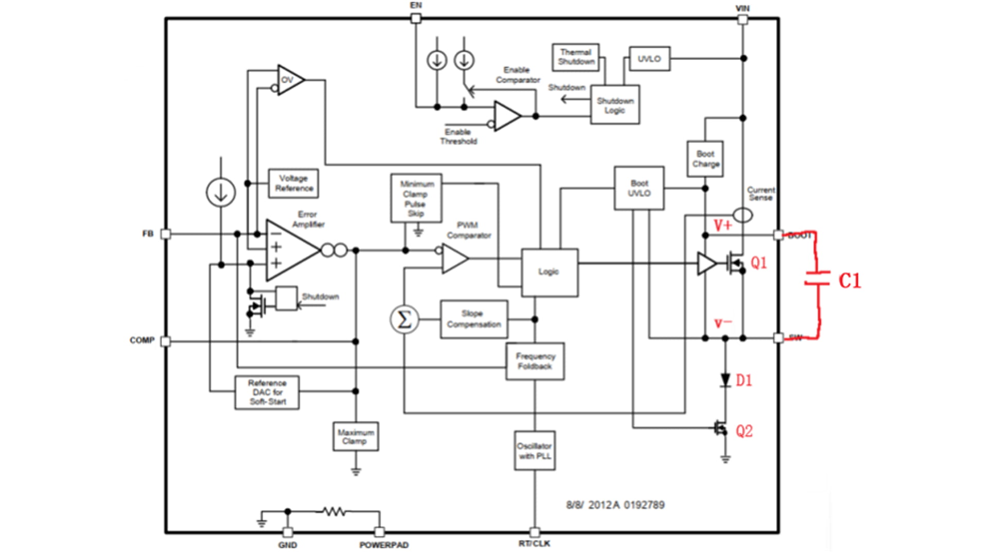
Figure 1 BUC power supply Typically, when designing an asynchronous buck power supply, a bootstrap capacitor is connected between the chip's SW and BOOT pins, such as C1 in Figure 1. The bootstrap capacitor utilizes the characteristic that the voltage across the capacitor cannot change suddenly. When a certain voltage is maintained across the capacitor, when the voltage at the negative terminal of the capacitor is increased, the voltage at the positive terminal remains at the original voltage difference at the negative terminal, thereby increasing the driving voltage. Figure 2 Buck chip internal structure diagram The buck chip shown in Figure 2 consists of two NMOS transistors, which alternately conduct in a complementary manner. The total input voltage VIN is fed through an internal voltage regulator, which outputs a DC low voltage Vb for charging Vboot. This internal voltage regulator is typically a low-dropout (LDO) power supply. During buck chip operation, when the low-side MOSFET Q2 is on, the SW voltage is 0. The LDO output voltage Vb charges the bootstrap capacitor C1, which then flows through the diode D1 and then the low-side MOSFET Q2. The voltage across the capacitor is approximately equal to Vb, and the BOOT pin voltage is now Vb. When the low-side MOSFET Q2 is off and the high-side MOSFET Q1 is on, the voltage at the SW pin rises from 0V to VIN. The S-pole of low-side MOSFET Q2 is directly grounded. As long as the G-pole outputs a high level (>Vth), low-side MOSFET Q2 will turn on. The S-pole voltage of high-side MOSFET Q1 is the input voltage VIN. To maintain the on-state of high-side MOSFET Q1, its gate drive voltage must be greater than VIN + Vgs(th). Since the voltage across the capacitor cannot change suddenly at this point, the BOOT pin is raised to a voltage greater than VIN (VIN + Vb). Capacitor C1 is connected in parallel to the power supply of the high-side MOSFET Q1's driver unit, HS Driver. The bootstrap capacitor C1 discharges to provide power to it, and the supply voltage is the voltage difference across the bootstrap capacitor. Due to the presence of the bootstrap capacitor, the gate-source drive voltage of high-side MOSFET Q1 meets the turn-on condition (Vgs > VIN + Vgs(th)), thus maintaining the on-state of high-side MOSFET Q1. As long as the voltage from the BOOT pin to the SW pin is above the BOOT UVLO threshold, high-side MOSFET Q1 remains on. When the voltage of the bootstrap capacitor drops below the BOOT UVLO threshold due to discharge, the high-side MOSFET Q1 is turned off and the low-side MOSFET Q2 is turned on, periodically charging the bootstrap capacitor, thereby implementing the PWM control mode of the buck power supply.
Read More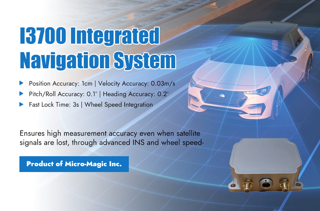
Inertial navigation systems (INS) play a crucial role in autonomous driving technology, especially in addressing the limitations of other sensors such as GPS, cameras, and LiDAR. It provides continuous, high-frequency, and undisturbed motion state information, and is one of the core components of autonomous driving perception and positioning. The Core Function of Inertial Navigation System The core function of inertial navigation system in autonomous driving is the perception of vehicle motion status. Measure the three-dimensional position, velocity, and attitude angle (including roll , pitch, yaw) of the vehicle. The inertial measurement unit (IMU), as the core sensor of INS, has a very high data update frequency (usually above 100Hz), far exceeding GPS (1-10Hz) and camera/LiDAR (10-30Hz), and can capture the instantaneous dynamic changes of the vehicle. 1. Key application scenario: Compensating for other sensor defects Usually in autonomous driving navigation systems, GPS signals are often lost or unreliable, causing GPS signal interruption or severe degradation, such as in tunnels, underground garages, and under elevated bridges where satellite signals are completely blocked; In urban canyons and areas with high-rise buildings, GPS signals are severely reflected and subject to multipath interference, resulting in a significant decrease or even failure in positioning accuracy; Under dense forests, leaves may also block satellite signals. At this point, INS systems typically play an important role. Through dead reckoning, based on the known precise position and attitude at the previous moment, the acceleration and angular velocity measured by IMU are integrated to calculate the current relative displacement and attitude change of the vehicle, thereby calculating the new position and attitude. This ensures the continuity of positioning. By providing high-frequency attitude information, even when the GPS signal is good, the high-frequency, high-precision attitude information (roll, pitch, yaw) provided by INS is difficult for other sensors to provide alone. The following table compares the navigation performance indicators of the I4500 Integrated Navigation System during satellite-assisted navigation versus satellite signal loss scenarios. I4500 System Performance Parameters Index (RMS) Comments Heading Accuracy Dual GNSS 0.1° 2m baseline Single GNSS 0.2° Need to maneuver GNSS failure retention accuracy 0.2°/min Attitude Accuracy GNSS is valid 0.1° GNSS failure retention accuracy 0.2°/min V-G mode (GNSS failure time unlimited, no acceleration) 2° Horizontal Positioning Accuracy GNSS is valid 1.2m Single point 2cm+1ppm RTK GNSS failure (60s) 20m 2. The core hub of multi-sensor fusion The modern auto drive system adopts sensor fusion technology without exception. INS is a key node in the fusion framework. ⚪ By integrating with GNSS, a GNSS/INS integrated navigation system is formed, which is the most classic and mature combination. GNSS provides absolute position and long-term stability, but updates are slow and susceptible to interference; INS provides high-frequency, continuous relative motion information and attitude, but there is cumulative error (drift). The Kalman filter utilizes the advantages of both to mutually correct, GNSS corrects the drift of INS, and INS provides continuous positioning and smooth GNSS output when GNSS fails. Secondly, it can improve overall accuracy and robustness, and the accuracy and reliability of the combined system are much higher than those of individual GNSS or INS. ⚪ By integrating with the speedometer, the speedometer provides wheel speed information (speed, distance traveled), which can assist in correcting INS errors in speed estimation, especially when the vehicle is driving straight. The following table shows the performance indicators of the I3700 integrated navigation system produced by Micro-Magic Inc. Even in the case of satellite signal loss, high measurement accuracy can still be achieved through the algorithm fusion of INS and wheel speedometer. I3700 Navigation Accuracy Indexs Lost Lock Time Navigation Mode Position Accuracy Velocity Accuracy Pitch/Roll Accuracy Heading Accuracy 3s Connect to odometer 1cm 0.03m/s 0.1° 0.2° 10s 1m 0.1m/s 0.1° 0.2° 60s 6m 0.1m/s 0.2° 0.35° ⚪ By integrating with visual/LiDAR SLAM, the high-frequency data of IMU can provide motion prediction for visual or LiDAR processing, reducing the computational complexity of image matching or point cloud matching, and improving real-time performance and robustness (especially in fast motion or weak texture environments). The precise attitude information (roll, pitch) provided by INS is crucial for correctly analyzing the geometric relationships of camera images or LiDAR point clouds on slopes and bumpy roads. Application Cases Taking the I6700 product launched by Micro-Magic Inc as an example, this system can integrate various auxiliary sensors such as GNSS, Odometer, Magnetometer, etc., and provide accurate heading correction function for vehicles in various operating scenarios I6700 Heading Correction Method Function Condition Comments GNSSDual antenna Heading Dual antenna enable Suitable for open fields Kinematic alignment Airplane、Automotive and Marine Suitable for large maneuvering environments, with a carrier speed of at least 3m/s GPSTrue Heading GPS enable Suitable for open fields Acceleration Alignment Helicopter mode Acceleration of at least 2.5m/s2 within 2 seconds Magnetic Heading Magnetic compass enable The magnetic field environment is relatively stable High precision inertial navigation system products launched by Micro-Magic Inc Summary: Inertial Navigation System (INS) is the backbone of autonomous driving positioning system. It provides continuous, high-frequency, and undisturbed vehicle motion status and attitude information, which is a key technology to ensure positioning continuity, robustness, and high-frequency response capability. Especially in challenging scenarios where GPS losing lock (tunnels, urban canyons), INS maintains its positioning capability through dead reckoning, which is an indispensable part of safety redundancy. Although its inherent cumulative error needs to be closely integrated with other sensors (GNSS, wheel speed sensors, vision, LiDAR) for correction, in the multi-sensor fusion framework, INS serves as the core hub, greatly improving the accuracy, reliability, and dynamic performance of the entire positioning system. With the advancement of IMU technology (such as the improvement of MEMS gyroscope accuracy and the miniaturization of solid-state laser gyroscopes) and the optimization of fusion algorithms, the role of INS in autonomous driving will become increasingly important.
Read More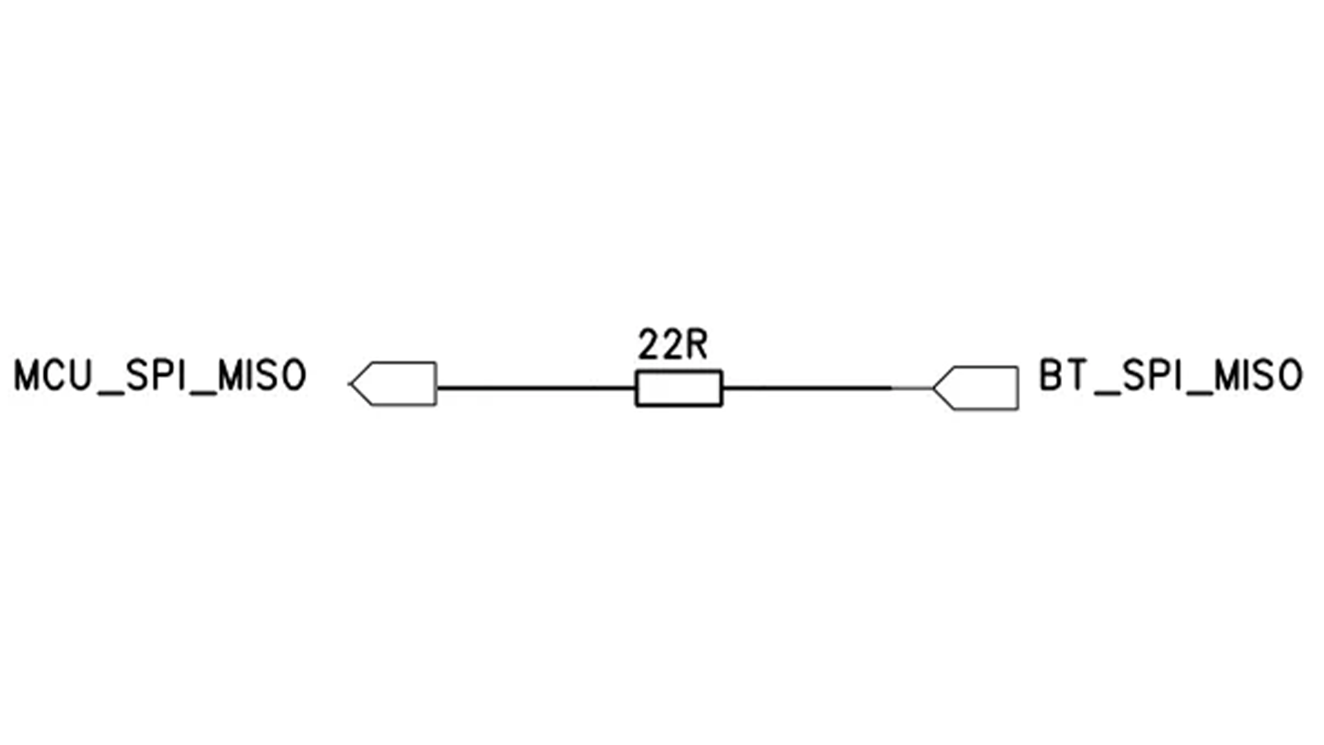
In circuits used for SPI bus communication with peripheral devices, a small resistor with a resistance of tens of ohms is typically connected in series with the signal line, as shown in Figure 1. This design achieves the following functions: 1. Impedance matching. When SPI signal lines are long or the load capacitance is large, the signal may be reflected at the end of the transmission line, causing waveform oscillation (ringing) or overshoot/undershoot. The series resistor acts as an impedance match at the source end (usually close to the master end), absorbing reflected energy and reducing signal integrity issues. This is particularly critical in high-speed SPI (e.g., tens of MHz) or long traces. 2. Reduce electromagnetic interference (EMI). SPI communication often operates at high speeds. The series resistor, along with the capacitance of the line and the load capacitance, forms an RC circuit. This circuit structure helps slow down the rising and falling edges of the signal, thereby preventing overshoot. This has a positive effect on EMI suppression, especially in high-speed circuits. 3. Current limiting and device protection. The resistor limits current flow in the event of an accidental short circuit (e.g., due to wiring errors), preventing damage to the master or slave device I/O ports. 4. Optimize debugging. During debugging, it's common to use an oscilloscope to capture waveforms. Connecting a resistor in series with the SPI signal line makes it easier to observe and debug the signal waveform using an oscilloscope, improving debugging efficiency.
Read More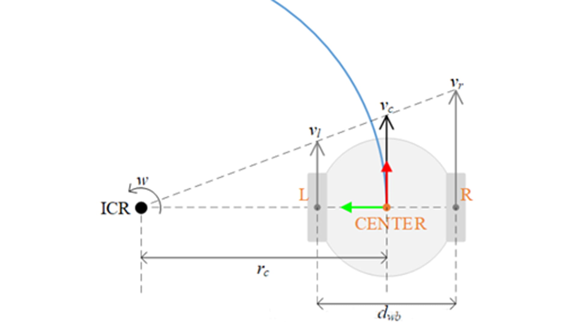
The application of wheel speed sensors in inertial navigation systems (INS) is mainly reflected in multi-sensor fusion and error correction, especially playing an important role in vehicle navigation. Inertial navigation systems (INS) mainly rely on gyroscopes and accelerometers to calculate position, velocity, and attitude through integration, but there is a problem of error accumulation. As a low-cost, high-frequency incremental sensor, the wheel speed sensors can effectively alleviate the problem of error divergence in inertial navigation. At present, in the multi-sensor information fusion system of integrated navigation, the role of the wheel speed sensors is mainly reflected in speed correction and mileage assisted positioning. The wheel speed sensor provides real-time longitudinal velocity, compares it with the acceleration integration result of INS, and fuses the data through Kalman filtering (EKF/UKF) to suppress INS velocity drift. In GPS denied environments (tunnels, underground garages), the wheel speed sensor provides mileage information to assist INS in calculating the relative position of the vehicle, reducing the accumulation of positioning errors. This article indirectly calculates the rate of change in heading angle by analyzing the wheel speed difference of the wheel speed sensor, providing auxiliary correction for vehicle heading navigation. The wheel speed sensors indirectly calculate the rate of change in heading angle (i.e. angular velocity) by measuring the speed difference between the left and right wheels (wheel speed difference), and its core principle is based on the vehicle kinematic model. 1. Basic model assumptions Assuming the vehicle has a rigid body and meets the following conditions: ⚪ Plane motion: The vehicle only moves within a horizontal plane (ignoring pitch and roll). ⚪ No slippage: There is no lateral slippage at the contact point between the tire and the ground (only considering longitudinal rolling). ⚪ Symmetrical wheelbase: The left and right wheelbase (distance between wheels) are fixed values. 2. The mathematical relationship between wheel speed difference and angular velocity The relationship between left and right wheel speed and linear speed is as follows: Left wheel linear velocity Right wheel linear velocity In which: : Left and right wheel speed (radians/second); : Effective rolling radius of tire (assuming constant) According to the instantaneous kinematics analysis of the vehicle, when the vehicle turns, the left and right wheels move around the same instantaneous center of rotation (ICR) (as shown in the figure) The angular velocity of the vehicle (the rate of change in heading angle) . The difference in linear velocity between the left and right wheels is generated by the rotation of the vehicle around the ICR, and the geometric relationship satisfies: , Among them, B is the distance between the left and right wheels (assuming a fixed value); R is the turning radius. Subtracting the two equations yields: Therefore, the rate of change in heading angle (angular velocity) is: 1. Corrections and limitations in practical applications ⚪ Calibration of wheelbase: The actual wheelbase may vary due to load or suspension deformation and needs to be calibrated regularly; The formula assumes that the left and right wheels are symmetrical, and the model needs to be adjusted for asymmetric vehicles. ⚪ Slip and error compensation: During rapid acceleration/braking, the tire slips, causing longitudinal slip and resulting in a wheel speed difference that does not match the true angular velocity. The solution is to introduce IMU angular velocity observations, fuse them through Kalman filtering, or dynamically adjust the slip rate compensation coefficient. ⚪ Tire radius variation: Changes caused by tire pressure, wear, or load variations require indirect calibration through external sensors (such as vision/LiDAR). 2. Example explanation Assuming the parameters of a certain vehicle are as follows: Track width B=1.5m, tire radius r=0.3m Left wheel speed: , Right wheel speed: Calculate the rate of change in heading angle: The vehicle turns left at an angular velocity of 0.4 radians per second. 3. Collaboration with other sensors ⚪ Integration with Inertial Navigation System (INS): The wheel speed sensor provides low-frequency but drift free angular velocity observations, which can correct the accumulated errors of the INS gyroscope. ⚪ Integration with GPS/vision: Long term absolute heading calibration to suppress deviations caused by slip or model errors in the wheel speed sensors. 4. Conclusion The formula for calculating the rate of change of heading angle through wheel speed difference using a wheel speed sensor is: Its advantage lies in strong real-time performance and no cumulative error, but it is limited by slip, tire parameter changes, etc. In practical systems, multi-sensor fusion (such as INS, GPS) is needed to improve robustness.
Read Moreleave a message
Scan to Wechat :