





Micro-Magic Inc recently announced that its customized AC-4 series quartz flexible accelerometer has been successfully applied to the navigation and control system of a certain type of high-speed flying vehicle, solving the problem of precise inertial measurement in severe aerodynamic heating and complex vibration environments. When flying at high speeds, the surface of the shell of such aircraft will experience sustained high temperatures due to intense aerodynamic friction. At the same time, complex flight attitudes and engine operation will also introduce strong vibrations and impacts. Under such "thermal-vibration composite" extreme environments, ordinary inertial sensors are prone to performance degradation or even failure, leading to "loss of lock" of navigation signals. This is one of the key technical bottlenecks in the development of the entire system. The design of the AC-4 series accelerometer is precisely aimed at addressing this challenge. The product adopts a unique high-temperature design and dual-torque structure, ensuring performance stability within the harsh temperature range of -55°C to 180°C. Its high mechanical shock resistance of up to 1000g and excellent vibration rectification error (<30μg/g²) indicators mean that it can accurately separate and measure useful acceleration signals in intense dynamic environments, rather than being overwhelmed by environmental noise. "For high-speed aircraft, the 'brain' of the control system relies on the most 'clean' and reliable attitude and acceleration data," explained the product manager of Micro-Magic. "The AC-4's bias value as low as less than 15mg and its scale factor monthly repeatability of less than 80 ppm provide a stable and reliable input benchmark for flight control. And its bandwidth exceeding 300Hz enables rapid response to dynamic changes in the aircraft, ensuring real-time and precise control. This is the key to achieving stable flight and precise guidance." The feedback from the customer confirms the performance of AC-4: "In our comprehensive environmental reliability test, AC-4 underwent a complete temperature-vibration-shock three-dimensional test profile. The results demonstrate that under extreme conditions of simultaneous high temperature and high-frequency vibration, its bias temperature coefficient (<50μg/℃) and scale factor temperature drift (<100ppm) are effectively controlled, and the output signal remains highly consistent and reliable. It successfully plays the role of a reliable 'sensory neuron' in the 'nervous system' of our next-generation aircraft." The General Manager of Micro-Magic stated, "Since its launch, the AC-4 platform has demonstrated unparalleled long-term reliability in the field of petroleum drilling. Today, we are introducing this time-tested and mature product to the cutting-edge aerospace sector, where equally stringent reliability standards are required. This is not merely a shift in application scenarios but a natural extension of our core technological strengths. We are honored to provide a solid force from the basic sensing field to promote the development of hypersonic technology."
Read More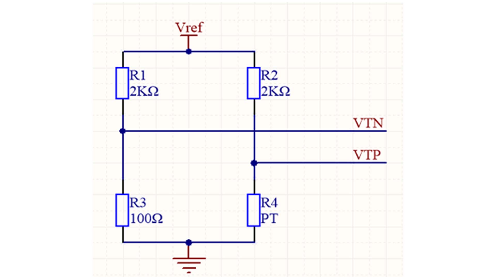
In industrial applications, to accurately measure temperature values, we typically use a PT100 bridge circuit to sample and convert resistance changes into voltage changes. To obtain different measurement ranges, the sampling resistors are divided into 100 ohms and 50 ohms. Method 1 and Method 2 are the measurement calculation formulas for PT100. The specific differences are as follows: Method 1: (PT100) Reference resistor R3 = 100Ω. This method cannot measure temperatures below zero. The measurement temperature range of Method 1 is >= 0℃. Substitute the values: R1 = R2 = 2000Ω; R3 = 100Ω; R4 = R; Let the measured voltage VT = VTP - VTN as Remove the denominator, Refine expressions Vref is the reference voltage acquired by the AD converter, and VT is the measured voltage. Method 2: (PT100) Reference resistor R3 = 50Ω, measuring resistance offset downwards by 50 ohms, measuring temperature range >=-125℃. Substitute the values: R1 = R2 = 2000Ω; R3 = 50Ω; R4 = R; Let the measured voltage VT = VTP - VTN Remove the denominator, Refine expressions Vref is the reference voltage acquired by the AD converter, and VT is the measured voltage. Through the calculation process above, we obtained the calculated resistance value of the PT100 by measuring the sampled voltage. To ultimately obtain the relationship between resistance and temperature, typical methods include table lookup and iterative methods.
Read More
As unmanned systems and robot applications move from laboratories to industrial and military grade scenarios, they pose unprecedented demands on the accuracy, reliability, and environmental adaptability of core sensors, especially IMUs. Traditional low-cost MEMS IMUs are unable to perform long endurance and high-precision tasks due to insufficient accuracy and large drift; However, high-end solutions such as fiber optic gyroscopes (FOGs) are limited in large-scale applications due to cost, size, and weight constraints. As a leading designer and manufacturer of Inertial Sensors from China, Micro-Magic Inc has launched the U-Series high-performance and high-precision MEMS inertial measurement units, including the U5000, U6300, and U7000,which are precisely filling this market gap. This series of products aims to completely change the navigation, guidance, and control performance of unmanned aerial vehicles (UAVs), unmanned vehicles (UGVs), unmanned ships (USVs), autonomous underwater robots (UUVs), and various robot platforms, providing core support for achieving truly autonomous "perception and decision-making" in complex environments. Taking the U6300 from Micro-Magic Inc as an example, they integrate high-performance three-axis MEMS gyroscopes and three-axis MEMS accelerometers, and achieve breakthroughs in key performance indicators through precise system level design and algorithm optimization. The gyroscope's zero bias instability can reach 0.1°/h,while the accelerometer's zero bias instability is as low as 10 μg. This indicator enables the U6300 model to meet the needs of most industrial and even some tactical applications, especially during GNSS signal interruptions, significantly reducing position estimation errors and achieving longer autonomous navigation time. U6300 has undergone comprehensive temperature compensation within a wide temperature range of -40°C to +85°C, ensuring output stability in extreme weather conditions. Meanwhile, its excellent anti-vibration and anti-impact capabilities enable it to firmly adhere to platforms such as industrial robots, off-road UGVs, or high-speed drones, and work continuously and stably under harsh conditions. At the same time, the U6300 supports high-frequency data output of 1000Hz, which can accurately capture fast motion details. Its compact size (38.6 x 44.8 x 10 mm) and lightweight (50g) design greatly facilitate system integration. The product manager of Micro-Magic Inc stated that the development of the U-series is based on the urgent market demand for high cost-effectiveness and high reliability IMUs. We have successfully elevated the performance of MEMS inertial sensors to a new level through the optimization of core MEMS chips and advanced calibration compensation algorithms. The U series IMU product is not just a component, but also a crucial step in providing our customers with the cornerstone of 'autonomous perception' for unmanned systems and intelligent equipment.
Read More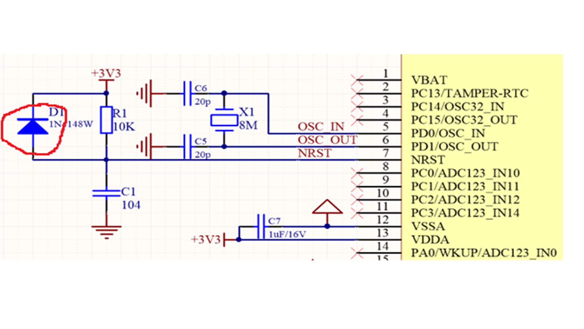
In the STM32 reset circuit shown in Figure 1, a switching diode is usually connected in parallel with the resistor terminal of the RC reset circuit. The main function of this diode is to accelerate the release of capacitor charge. Figure 1 STM32 reset circuit Figure 2 Discharge path of STM32 reset circuit In an RC reset circuit, a discharge diode is indispensable, its main function being rapid discharge. When the power is off or there is a momentary power outage due to interference, the charge stored in the capacitor needs to be released through some path to ensure proper reset upon the next power-on. Without a diode, when the power-off interference pulse is narrow, the capacitor discharges through resistor R1, which has a large resistance, resulting in a slow discharge speed. The RC circuit cannot fully discharge at the moment of power failure, and the system cannot automatically reset upon power restoration. The momentary power outage interference can cause the program to stop running normally, leading to program erratic behavior or entering an infinite loop. The addition of a diode provides a rapid discharge path for the capacitor. Due to the diode's very low on-resistance, as shown in the STM32 reset circuit discharge path in Figure 2, the charge in capacitor C1 discharges rapidly through diode D1, ensuring the stability and reliability of the reset circuit. When the power is off, the capacitor discharges rapidly to ground through the diode. When the power is restored, the capacitor has already discharged completely and can immediately begin the charging process, triggering the reset operation. This rapid discharge process ensures that the reset circuit can quickly return to its initial state after a power outage or abnormal power supply.
Read More
In the era of profoundly evolving modern warfare, precise and reliable autonomous orientation has become a critical determinant of battlefield success. Confronted with increasingly complex electromagnetic environments and the severe challenge of vulnerable satellite navigation systems to interference, the Fiber Optic Gyroscope (FOG) north finder, with its excellent technical performance, provides a new directional benchmark solution for various military platforms, significantly improving its combat adaptability and battlefield survival ability in extremely harsh environments. The NF3000 FOG North Finder launched by Micro-Magic Inc integrates high-precision fiber optic gyroscope and inertial measurement unit (IMU), equipped with precise indexing mechanism and advanced control calculation system. Excellent north finding accuracy of ≤ 0.1°secψhas been achieved, and the complete autonomous north finding process can be completed within 3 minutes. This performance indicator has reached the international advanced level. Its wide working latitude range covers -70 ° to+70 °, coupled with an ultra wide working temperature range, ensuring that the equipment can maintain stable and reliable operating performance in the vast majority of global regions and extreme weather conditions. NF3000 has fully considered the strict requirements of the battlefield environment in its engineering design. The exquisite structural design enables it to be easily integrated into various military equipment, while the low power consumption characteristic of ≤50W greatly enhances the battlefield applicability and sustained combat capability of the system. The high-definition OLED display screen equipped with the equipment can display key data such as azimuth, roll angle, and pitch angle in real time, and output accurate measurement results through the high-speed RS-422 interface, providing timely and reliable azimuth and attitude information support for the combat system. In extreme battlefield environments where satellite navigation is limited or completely ineffective, the NF3000 demonstrates unique combat value. Its fully autonomous north finding capability does not rely on any external signals, providing a sustained and stable position reference for command and control systems, precision strike firepower, and battlefield reconnaissance equipment. The high-precision attitude measurement capability of ≤ 0.1° and full range measurement from 0° to 360° of the equipment ensure that various combat platforms always maintain accurate orientation under complex terrain conditions. Particularly noteworthy is the NF3000's rapid start-up time of ≤30 seconds, which fully meets the stringent requirements for quick reaction capabilities in modern battlefields. Its rugged mechanical design and precision mounting interfaces, validated through rigorous environmental adaptability tests, ensure long-term operational stability under harsh conditions including intense shock and vibration. The system employs a reliable electrical connection architecture, complete with dedicated power and communication interfaces, to guarantee signal integrity even within complex electromagnetic environments. The NF3000 FOG North Finder, with its outstanding performance, provides precise and reliable autonomous orientation capabilities for various combat platforms, ensuring combat effectiveness in complex electromagnetic environments. Its fast response and stable and reliable characteristics enable military equipment to maintain precise combat capabilities even under limited satellite navigation conditions, providing solid technical support for improving the overall combat effectiveness.
Read More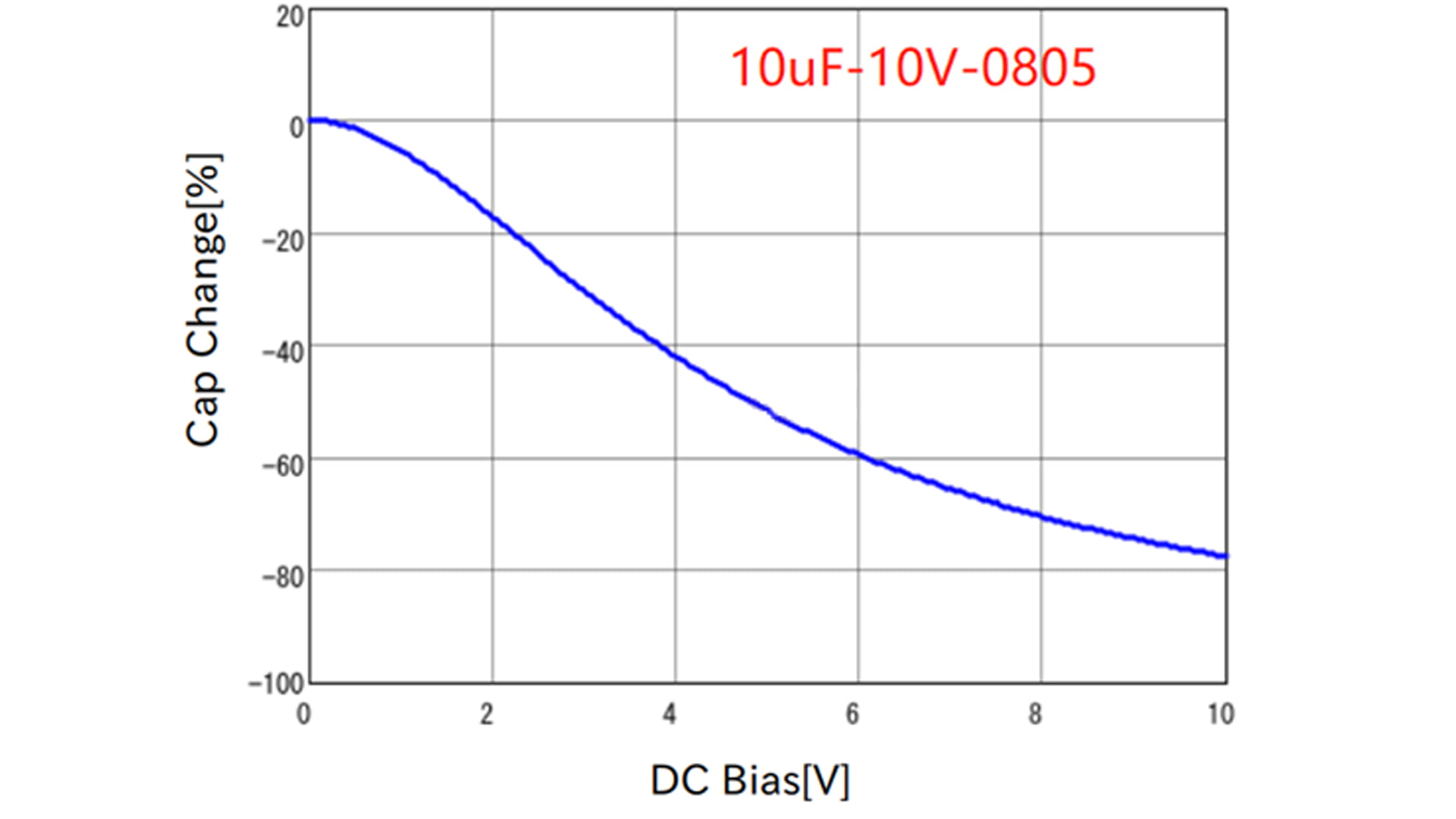
When designing switching power supply circuits, we typically calculate the output ripple using the following formula: If the capacitor used is an MLCC (Multi-Layer Ceramic Capacitor), its ESR is negligible due to its very low value. Therefore, based on the input/output voltage, switching frequency, and target ripple, the capacitance can be calculated using the following formula: However, the capacitance value calculated using the above formula resulted in a larger output ripple during actual testing. Why is this? This is because MLCC (Multi-Layer Ceramic Capacitors) have a DC bias characteristic: applying a DC voltage to the capacitor reduces its capacitance. Figure 1 below shows the DC bias characteristic of Murata's 22uF/10V capacitor. Figure 1 As can be seen, when a DC voltage of 5V is applied to the capacitor, its capacitance is reduced to approximately 50% of its initial value. The DC bias characteristic of MLCC capacitors is very pronounced; the larger the capacitance, the faster the capacitance decreases with increasing voltage, which must be considered in circuit design. Generally, the DC bias characteristics of MLCC capacitors have the following characteristics: ① The larger the capacitance, the more pronounced the bias characteristic; the capacitance decreases more with increasing voltage. ② For capacitors of the same capacitance but different voltage ratings, the capacitance decreases approximately the same under the same voltage (there is no capacitor with a high voltage rating that decreases less). ③ For capacitors of the same capacitance and voltage rating, the larger the package, the slower the capacitance decreases. The capacitance decay of MLCCs is an objective reality. Design should be based on the capacitance under the actual bias voltage, not the nominal capacitance. For example, if a circuit requires a 10uF capacitor, and an X7R type MLCC (10V rated) is selected, with an actual bias voltage of 5V (at which point the capacitance decays by approximately 50%), then two capacitors with a nominal capacitance of 10uF should be connected in parallel to ensure that the actual capacitance meets the requirement.
Read More
Recently, Micro-Magic Inc, a provider of inertial technology solutions, officially released its new generation of Ring Laser Gyroscope series products. As a new masterpiece for strategic navigation and high-precision inertial measurement applications, the launch of this series of products marks another major breakthrough for the company in the field of high-precision and high reliability inertial sensing, aiming to meet the increasing demand for strategic navigation performance in aerospace, defense technology, high-end industry and other fields. The GR series RLG products integrate advanced laser optical technology and mature temperature control processes, with high stability, wide dynamic range, and excellent anti-interference performance. It has advantages such as fast start-up and stable proportional factor, and can maintain stable output even in extreme temperatures (-40℃ to +70℃) and strong vibration environments. Not only does it meet the strict requirements of traditional inertial navigation systems for accuracy and reliability, but it also provides reliable angular motion perception capability for the new generation of high dynamic platforms. In strategic navigation applications such as long endurance unmanned aerial vehicles, satellite attitude control, ship inertial navigation systems, and missile guidance, the GR series RLG products, with their low zero bias error and high repeatability, can effectively improve the autonomous navigation and attitude control accuracy of the system in complex environments. Meanwhile, its compact structural design and lightweight body make it highly suitable for high integration platforms with limited space. The GR series launched four products (G-R30, G-R50, G-R70, G-R90) based on different performance indicators to meet customers' needs for different application scenarios. The technical director of Micro-Magic stated, “The GR series RLG is not just a product, It is our response, stemming from a profound understanding of customer challenges in strategic applications. We firmly believe that with its excellent precision, strong environmental adaptability, and outstanding reliability, the GR series products will become one of the most trusted core components for our partners in promoting innovation in high-end navigation and autonomous systems”.
Read More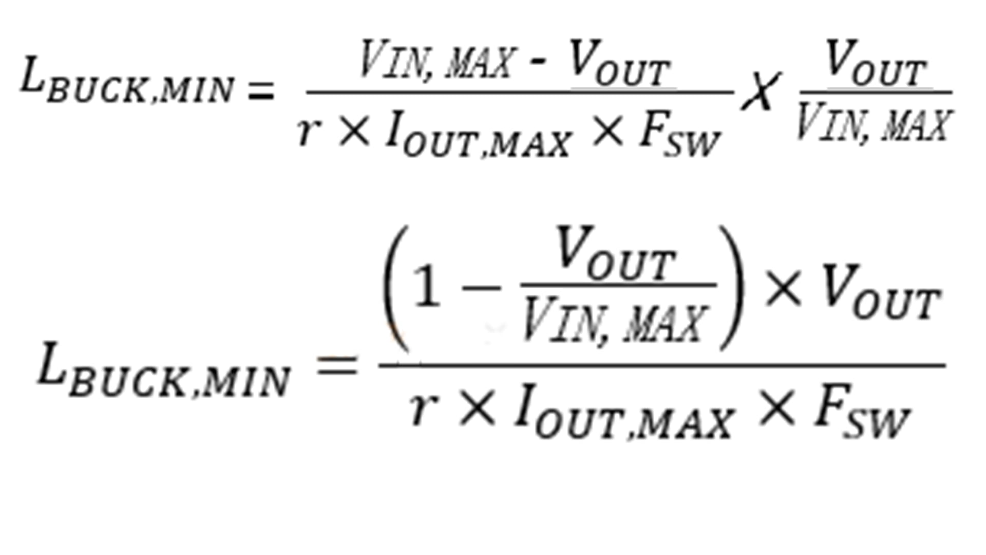
In a step-down switching converter, the theoretical peak current that the power inductor can withstand is IL,PK=(1+r/2)×IOUT. This is the basis for the minimum value of the rated current or saturation current of the power inductor. The actual selection value needs to be greater than the theoretical value of the peak current. Once the inductance value and other conditions of the power inductor are determined, the actual peak current of the inductor is Ipeak = Iout,max + ∆I_L/2 (where ∆I_L is the actual ripple current on the inductor after the inductance value is determined). The formula for calculating the minimum value of the power inductor in a BUCK circuit is as follows: Where VIN,MAX is the maximum input voltage that the BUCK circuit needs to support, VOUT is the typical output voltage, FSW is the switching frequency, IOUT,MAX is the maximum load current that needs to be supported, and r is the ripple current coefficient, which is typically set to 0.3~0.5. The above formula is the basis for determining the minimum power inductance value in the BUCK buck converter. The actual value must not be less than the theoretically calculated value; otherwise, the actual ripple current and other parameters in the circuit will not meet the target values in the design requirements. By transforming the above formula, we obtain the formula for calculating the minimum power inductance value, as shown below: Therefore, it can be seen that the input voltage VIN is directly proportional to the inductance L; the larger the input voltage (the maximum input voltage that needs to be supported is VIN,MAX), the larger the required inductance. If the designed BUCK circuit only needs to support the typical input voltage value VIN,TYP, that is, the input voltage is a fixed value, then the calculation of the minimum power inductance mentioned above can also use VIN,TYP.
Read More
In the fields of inertial navigation, aerospace, and precision industrial measurement, high-precision and highly synchronized acquisition of physical signals is the core to ensuring system performance. The 32-bit high-precision A/D conversion circuit specifically designed for accelerometers, introduced by Micro-Magic Inc, is a key component tailored for such high-end applications. With its exceptional performance and flexible architecture, it provides a solid foundation for building reliable high-precision inertial navigation signal acquisition systems. The core advantage of this A/D board lies in its exceptionally high measurement accuracy and stability. Supporting a current input range of ±50mA, combined with 32-bit A/D conversion capability, it can precisely capture minute current variations output by accelerometers. Within the full operating temperature range (-40°C to +70°C), its zero temperature coefficient is better than ±2nA/°C, and the scale factor temperature coefficient is below 3.0 ppm/°C. This means the system can maintain extremely low measurement drift even under complex ambient temperature fluctuations, ensuring long-term accuracy in navigation solutions. Additionally, the product boasts ultra-high stability, with zero stability and scale factor stability reaching the nA and ppm levels respectively, guaranteeing repeatable and reliable data output while effectively reducing the system's noise floor. Inertial navigation systems require extremely strict synchronization of multi axis data. This A/D board provides a precise synchronization solution to ensure data spatiotemporal consistency: Internal/external synchronization mode: it can be flexibly switched according to system instructions. In internal synchronization mode, the board autonomously generates a sampling clock; In external synchronization mode, RS422 differential synchronization signals are received from the navigation computer to achieve a unified sampling time for the entire system, perfectly eliminating timing errors between channels. ⚪ Latching and triggering: Latching the A/D values of all channels at the falling edge of the synchronization signal ensures that the acceleration and temperature data of the X, Y, and Z axes are captured at the same moment, providing a spatiotemporal consistent data source for subsequent navigation algorithms. Inertial navigation systems require extremely strict synchronization of multi axis data. This A/D board provides a precise synchronization solution to ensure data spatiotemporal consistency: ⚪ Internal/external synchronization mode: it can be flexibly switched according to system instructions. In internal synchronization mode, the board autonomously generates a sampling clock; In external synchronization mode, RS422 differential synchronization signals are received from the navigation computer to achieve a unified sampling time for the entire system, perfectly eliminating timing errors between channels. ⚪ Latching and triggering: Latching the A/D values of all channels at the falling edge of the synchronization signal ensures that the acceleration and temperature data of the X, Y, and Z axes are captured at the same moment, providing a spatiotemporal consistent data source for subsequent navigation algorithms.
Read More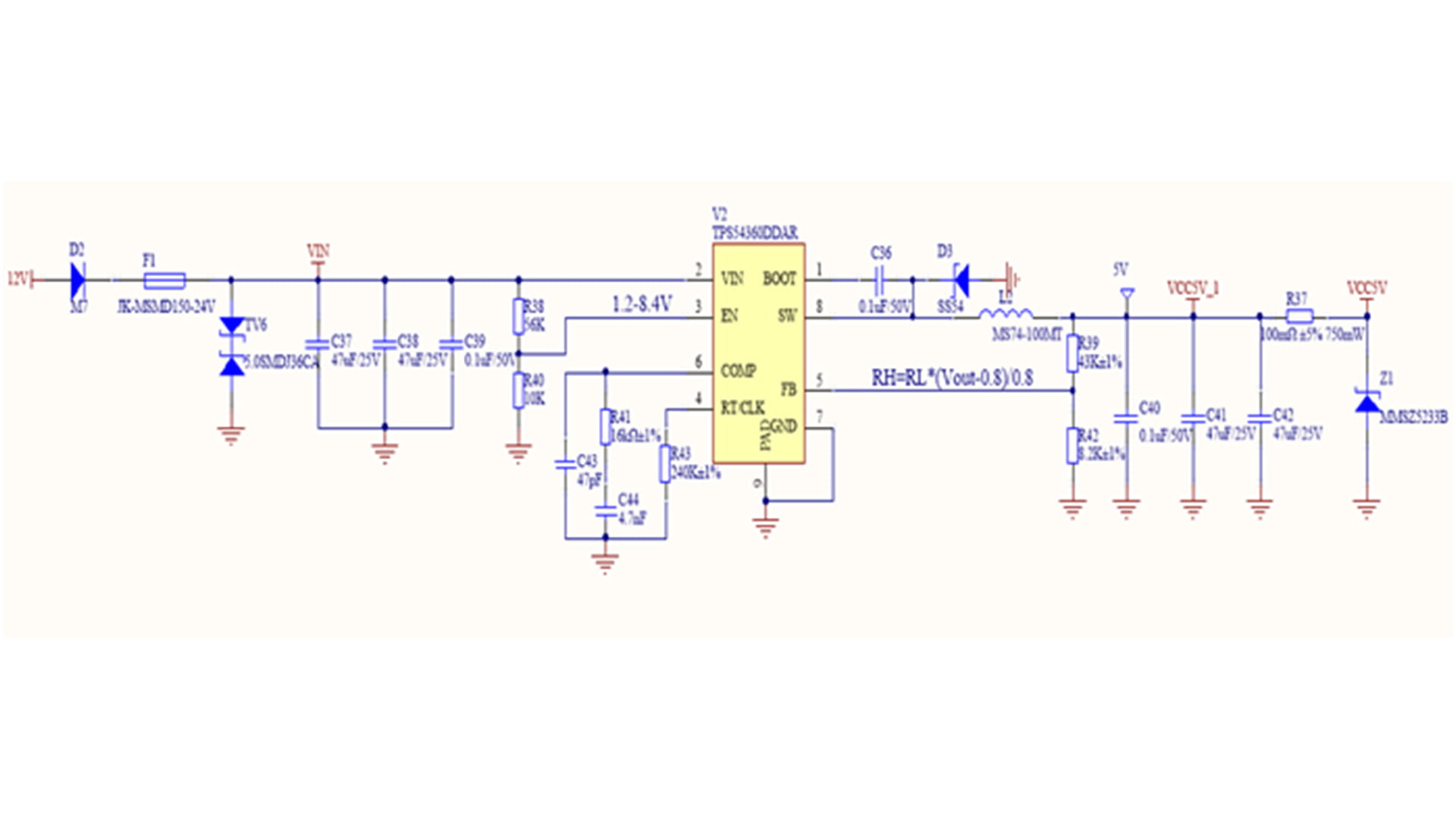
Figure 1. Non-synchronous BUCK converter topology Figure 1 shows the topology of an asynchronous BUCK converter. Asynchronous BUCK converter chips typically integrate only the high-side MOSFET internally. A freewheeling diode needs to be installed between the SW pin and GND as the freewheeling path for the power inductor when the high-side MOSFET is turned off. The selection of the freewheeling diode must meet at least the following two hard criteria (1)(2) and two optimization criteria (3)(4): (1) The reverse operating voltage VRRM of the freewheeling diode must be equal to or greater than the maximum input voltage VIN(max). (2) The forward conduction current IF(AV) of the freewheeling diode must not be less than Iout(max)*(1-D), where D is the duty cycle of the buck converter, and Iout(max) is the maximum load current that the buck converter can support. For a more stringent selection of the freewheeling diode's overcurrent capability, it can be selected to be greater than or equal to the peak current on the inductor IOUT+(ΔIL)/2. (3) The smaller the forward voltage drop VF, the smaller the power loss caused by this parameter, and the higher the power efficiency. (4) The faster the switching speed from the on state to the off state (the smaller the reverse recovery time trr), the smaller the reverse recovery loss, and the higher the power efficiency, the better. Schottky barrier diodes (SBDs) are ideal choices for freewheeling diodes due to their small forward voltage drop and fast reverse recovery time (typically tens of nanoseconds or even a few nanoseconds), reducing power losses in the freewheeling diode. To design a step-down DC-DC converter with a DC input voltage range of 9-36V, a typical input voltage of 12V, an output voltage of 5V, and a maximum load capacity of 5A, a Schottky diode with a reverse operating voltage of 40V and a forward current greater than 5A is selected because its maximum input voltage is 36V. As shown in Figure 2, the SS54 Schottky diode has a reverse operating voltage of 40V, an average rectified current of 5A, and a maximum forward voltage drop of 0.55V at a forward current of 5.0A, meeting the circuit requirements. Figure 2 Electrical parameters of SS54 Schottky diode When the input voltage is a typical 12V, the duty cycle is a typical 5/12, and the average current flowing through the freewheeling diode is 5.0A*(1-5/12)=2.917A. When the input voltage is the maximum value of 36V, the duty cycle is a minimum of 5/36, and the maximum average current flowing through the freewheeling diode is 5.0A*(1-5/36)=4.3A. As shown in Figure 3, D3 (SS54) in the TPS54360DDAR circuit design example is the selected freewheeling diode. Figure 3. TPS54360DDAR circuit design example
Read More
Significant progress has been made in the field of inertial technology in China - Micro Magic Inc recently announced that its high-performance inertial navigation system IF3700 has been successfully applied to the industry-leading "Tianhang Intelligence" new generation high-end industrial drone platform. This cooperation marks a comprehensive breakthrough in key indicators such as adaptability to complex environments and long-term stability for domestically produced high-precision inertial sensors, providing a core guarantee for reliable operation of industrial drones in challenging scenarios. In professional scenarios such as power inspection, high-altitude surveying, and emergency reconnaissance, industrial drones often face severe challenges such as strong electromagnetic interference, severe temperature changes, and continuous body vibration. The performance fluctuations of traditional sensors can easily lead to positioning drift and attitude misalignment, directly affecting operational safety and data quality. The technical director of "Tianhang Intelligence" said, "We have been looking for a sensor that can provide stable and accurate heading and attitude measurement throughout the entire mission cycle, and the appearance of IF3700 is timely." The successful application of IF3700 is attributed to its outstanding performance in multiple key performance parameters, which directly determine the reliability of drone navigation systems under extreme conditions. The IF3700 adopts a high-precision closed-loop fiber optic gyroscope with a full temperature of 0.01°/h and a 20 μg high-precision quartz accelerometer, with autonomous compass function. It can still achieve attitude accuracy of ≤ 0.003° and heading maintenance accuracy of ≤ 0.01°/h in pure inertia mode, demonstrating strong environmental adaptability. At the same time, the system supports inertial/satellite integrated navigation mode, with a position accuracy of centimeter level (RTK mode) and a velocity accuracy of better than 0.02m/s, effectively improving the operational capability of unmanned aerial vehicles in GNSS signal interference prone areas such as urban canyons and forest areas. In addition, IF3700 has rich interface configuration and high data update rate (up to 800Hz), which can flexibly interface with flight control, load and ground station systems, meeting the strict requirements of real-time and integration for industrial grade drones. The "Tianhang Intelligent" drone equipped with the IF3700 inertial navigation system has been validated for its value in multiple harsh scenarios. In surveying missions over complex plateau terrain, even with weak GPS signals, the IF3700 maintained centimeter-level flight path accuracy through its stable system output, successfully accomplishing high-precision 3D modeling. During high-voltage live-line inspection tasks, even when operating in strong electromagnetic environments, the IF3700 system remained completely immune to interference, delivering robust and reliable navigation and attitude data that formed the core foundation for autonomous obstacle avoidance and precise hovering. In emergency supply delivery operations, despite enduring substantial temperature variations during long-endurance, day-and-night missions, the IF3700 system demonstrated exceptional temperature stability, ensuring no degradation in navigation accuracy throughout the entire process. Micro Magic's Product Manager stated: "The success of the IF3700 system in the high-end industrial drone sector is just the beginning. It demonstrates that domestic core sensors are fully capable of supporting the development needs of intelligent equipment. We will continue to deepen our expertise in inertial technology, providing more unmanned platforms with a precise and reliable 'Perception Heart'."
Read More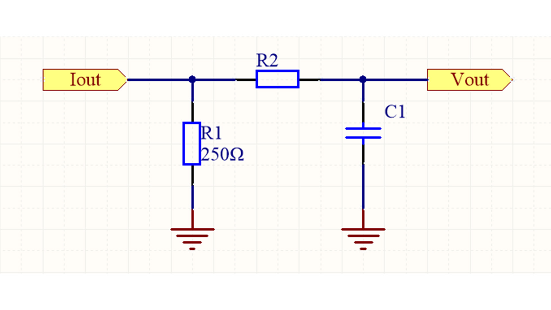
The previous article mentioned that in order to suppress the influence of high-frequency noise, the 4-20mA current sampling circuit needs to add an RC low-pass filter before ADC sampling. The RC low-pass filter circuit shown in Figure 1 is adopted, where R2 is 1.6K and C1 is 0.1uF. Then the cutoff frequency fc is approximately 1KHz. Figure 1 RC low-pass filter The following analysis examines its noise suppression capability through practical calculations, using a 200Hz in-band signal and a 5kHz out-of-band noise signal as examples to calculate its amplitude-frequency response. The output of a typical resistor divider is shown in Figure 2. Figure 2 Resistor voltage divider output The RC filter uses an equivalent structure, replacing R2 with a capacitor. First, we replace R2 with the capacitive reactance (XC) of the capacitor, obtaining the output expression of the RC voltage divider as shown in Figure 3: Figure 3. Resistor-capacitor voltage divider output The expression for the capacitive reactance of the capacitor is as follows: Figure 4. Expression for capacitive reactance of a capacitor In the design example above, R ≈ 1600Ω and C = 100nF. We assume the amplitude of VIN is 1V, and calculate the amplitude of VOUT using a sine wave frequency of 200Hz (Figure 5): Figure 5 The calculation results in Figure 5 show that the amplitude of the 200Hz signal remains essentially unchanged, which is consistent with the expectation of maintaining the signal amplitude without attenuation while suppressing noise. Next, let's see how the filter successfully attenuates the 5kHz noise component (Figure 6). Figure 6 The calculation results in Figure 6 show that the noise amplitude is only about 20% of its original value, which demonstrates that the suppression effect on out-of-band noise is significant.
Read Moreleave a message
Scan to Wechat :
